
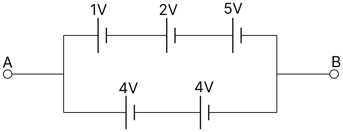
Five DC sources (cells) of given emf are shown in the figure emf of the battery AB is :
- 8 V
- 16 V
- 4 V
- 2 V
Answer
8 V
Reason — The five cells are arranged in two rows connected between the same two points A and B.
In the upper row the three cells of emfs 1 V, 2 V and 5 V are joined in series, so the net emf of this row is
1 V + 2 V + 5 V = 8 V
In the lower row the two cells of emf 4 V each are joined in series, so the net emf of this row is
4 V + 4 V = 8 V
The two rows are connected in parallel between A and B. When cells of equal emf are joined in parallel, the emf of the combination is equal to the emf of one row. Hence the emf of the battery AB is 8 V.
A cell of emf 1.5 V gives a current of 15 A when connected directly to an ammeter of 0.04 Ω resistance. The internal resistance of the cell is :
- 0.04 Ω
- 0.06 Ω
- 0.1 Ω
- 1.0 Ω
Answer
0.06 Ω
Reason — For a cell of emf E and internal resistance r sending a current I through an external resistance R,
Here E = 1.5 V, I = 15 A and R = 0.04 Ω. Substituting,
A current of 2.0 A passes through a cell of emf 1.50 V and internal resistance 0.15 Ω from the negative to the positive terminal. The terminal voltage of the cell will be :
- 1.35
- 1.50
- 1.00
- 1.20
Answer
1.20
Reason — Inside a cell which is being discharged, the current flows from the negative to the positive electrode. Hence the cell is delivering current and its terminal potential difference is
Substituting E = 1.50 V, I = 2.0 A and r = 0.15 Ω,
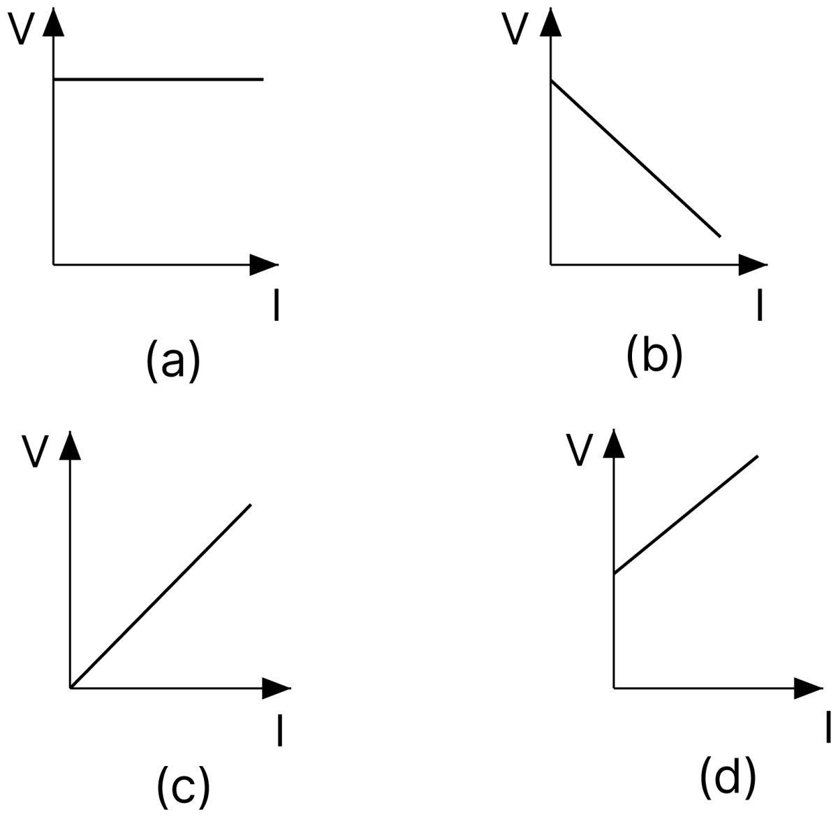
Following are the graphs between current I drawn from a cell and the terminal voltage V of the cell. Which one is correct?
Answer
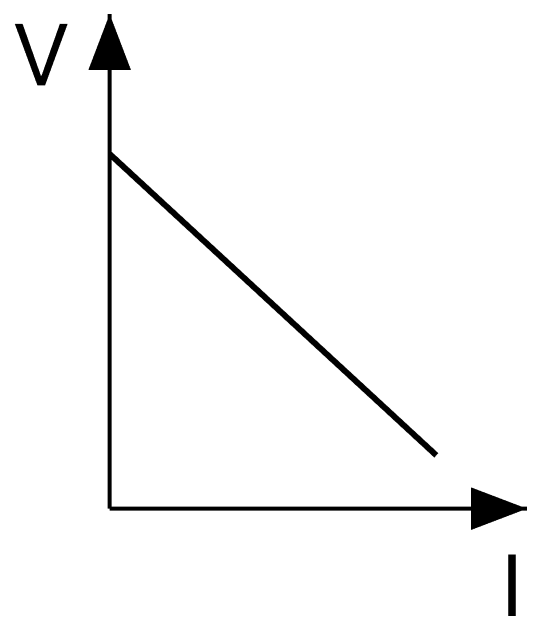
Reason — For a cell of emf E and internal resistance r delivering a current I, the terminal potential difference is
Comparing with the straight-line form y = mx + c, the graph of V against I is a straight line of negative slope (− r) with intercept E on the V-axis. Thus V is maximum and equal to E when I = 0, and falls uniformly as the current drawn increases. Only graph (b) shows a straight line starting at a finite value on the V-axis and decreasing with I.
A cell of emf E and internal resistance r is connected to an external resistance r. The PD across the terminals of the cell is :
- E
- 2 E
- E/2
- E/4
Answer
E/2
Reason — The external resistance and the internal resistance are both equal to r, so the current in the circuit is
The terminal potential difference is the potential drop across the external resistance,
Two unequal resistances joined in parallel are connected to a cell. Which of the following statements is true?
- Current is same in both.
- Potential drop is same in both.
- Current is more in greater resistance.
- Potential drop is smaller in smaller resistance.
Answer
Potential drop is same in both.
Reason — In a parallel combination both resistances are connected between the same two points of the circuit, so the potential difference across each of them is the same and equal to the terminal potential difference of the cell.
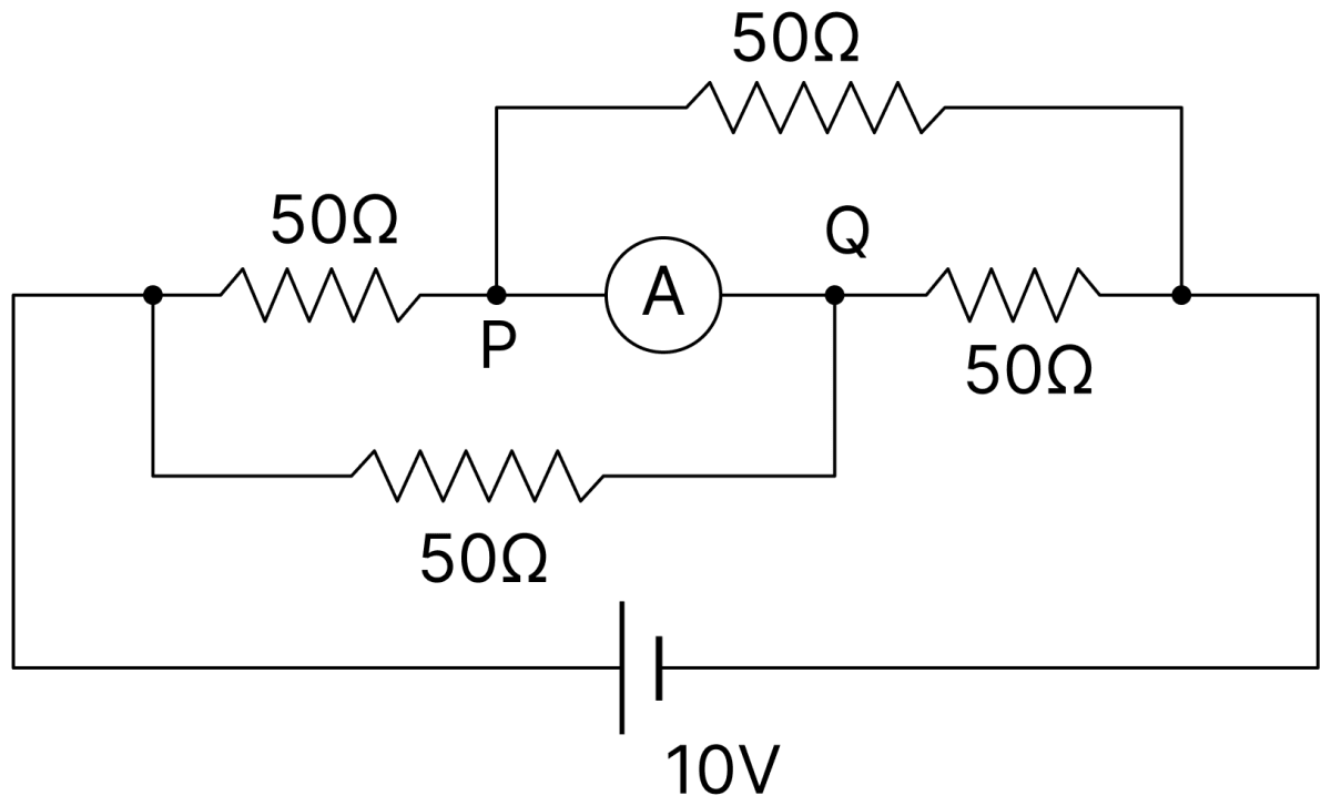
In the given network of resistors, the ammeter A will read :
- 50 mA
- 200 mA
- 500 mA
- zero
Answer
zero
Reason — The four 50 Ω resistors form the four arms of a Wheatstone bridge across the 10 V cell, and the ammeter A is connected in the arm PQ joining the two junctions of the bridge.
For the bridge the ratio of the resistances of the two arms on one side is
and that of the two arms on the other side is also
The condition of balance of the Wheatstone bridge is therefore satisfied. At balance the two junctions P and Q are at the same potential, so no current flows in the arm joining them. Hence the ammeter reads zero.
A student connects four cells, each of emf 1.5 V and internal resistance 0.25 Ω in series but one cell has its terminals reversed. This battery sends current in a 2 Ω resistor. The current is :
- zero
- 1 A
- 1.5 A
- 2.5 A
Answer
1 A
Reason — When one cell is reversed, its emf opposes the emfs of the remaining three cells. Hence the net emf of the battery is
The internal resistances add up in series irrespective of the direction in which a cell is connected, so the total internal resistance is
The current sent in the external resistance R = 2 Ω is
Five resistors are connected as shown in figure. The effective resistance i.e., equivalent resistance between the points A and B is :
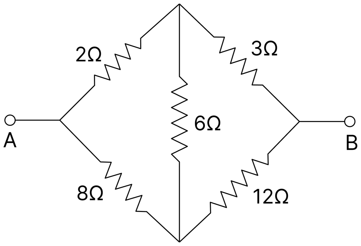
- 4 Ω
- 5 Ω
- 15 Ω
- 20 Ω
Answer
4 Ω
Reason — The five resistors form a Wheatstone bridge in which 2 Ω and 3 Ω are the arms of the upper branch, 8 Ω and 12 Ω are the arms of the lower branch, and 6 Ω is the arm joining the two junctions.
Testing the condition of balance,
The bridge is balanced, so no current flows through the 6 Ω resistor and it may be omitted.
The upper branch then gives 2 + 3 = 5 Ω and the lower branch gives 8 + 12 = 20 Ω, and these two are in parallel between A and B.
Potential gradient K remains constant until :
- current in potentiometer wire remains constant
- potential difference across the potentiometer wire remains constant
- emf of the testing cell remains constant
- none of the above
Answer
current in potentiometer wire remains constant
Reason — If the potentiometer wire of length L has resistance R and carries a current I from the driving cell, the potential difference across the whole wire is IR and the potential gradient is
For a given wire R and L are fixed, so K depends only on the current I in the wire. Hence the potential gradient stays constant so long as the current in the potentiometer wire remains constant.
Null method is superior over deflection method because :
- in this method no current is drawn from the source
- result is not affected due to wrong calibration of the meter (galvanometer) or due to imperfection in taking readings
- result is not affected when resistance changes due to heating effect of current
- none of the above
Answer
result is not affected due to wrong calibration of the meter (galvanometer) or due to imperfection in taking readings
Reason — In a null method the galvanometer is used only as a null detector, that is, merely to indicate whether the current through it is zero or not. The measured quantity is obtained from the balancing condition and not from the magnitude of the deflection.
Hence the wrong calibration of the galvanometer, or an error in reading its scale, cannot affect the result. In a deflection method, on the other hand, the value of the quantity is read from the size of the deflection, so it depends directly on the calibration of the instrument.
Figure represents a part of the closed circuit. The potential difference between points A and B (VA − VB) is :

- +9V
- −9V
- +3V
- +6V
Answer
+9V
Reason — A current of 2 A flows from A to B. Going from A to B, the potential falls across each resistor in the direction of the current and also falls on passing through the cell from its positive to its negative terminal.
Drop across the 2 Ω resistor = 2 × 2 = 4 V
Drop across the cell = 3 V
Drop across the 1 Ω resistor = 2 × 1 = 2 V
Hence,
The emf of a cell is E. When it is short-circuited, then its terminal voltage is :
- E
- E/2
- zero
- E/3
Answer
zero
Reason — When the cell is short-circuited the external resistance R becomes zero, so the maximum current is drawn from the cell,
The terminal potential difference is then
Thus the whole of the emf is used up in driving the current through the internal resistance of the cell itself.
Two batteries of emf E1 and E2(E2 > E1) and internal resistances r1 and r2 respectively are connected in parallel as shown in the figure.
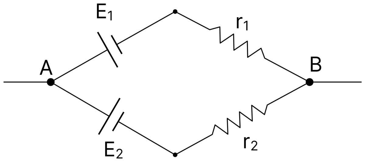
- The equivalent emf Eeq of the two cells is between E1 and E2, i.e., E1 < Eeq < E2.
- The equivalent emf Eeq is smaller than E1.
- The Eeq is given by Eeq = E1 + E2 always.
- Eeq is independent of internal resistances r1 and r2.
Answer
The equivalent emf Eeq of the two cells is between E1 and E2, i.e., E1 < Eeq < E2.
Reason — For two cells joined in parallel, the emf of the equivalent cell is
This expression is a weighted mean of E1 and E2, E1 being weighted by r2 and E2 by r1. A weighted mean of two quantities always lies between them, so E1 < Eeq < E2.
n identical cells, each of emf E and internal resistance r, are joined in series to form a closed circuit. The potential difference across any one cell is :
- zero
- E
Answer
zero
Reason — The n cells form a closed circuit among themselves, so there is no external resistance and the only resistance in the circuit is the total internal resistance nr. The current in the circuit is
The potential difference across any one cell is
Kirchhoff's current law is a consequence of the conservation of :
- energy
- momentum
- charge
- mass
Answer
charge
Reason — Kirchhoff's current law (junction rule) states that the algebraic sum of the currents meeting at a junction in a circuit is zero, that is, the total current entering a junction equals the total current leaving it.
Since current is the rate of flow of charge, this means that no charge is accumulated at or lost from the junction. Hence the junction rule is a statement of the conservation of charge.
The figure shows currents in a part of electric circuit. The current I is :
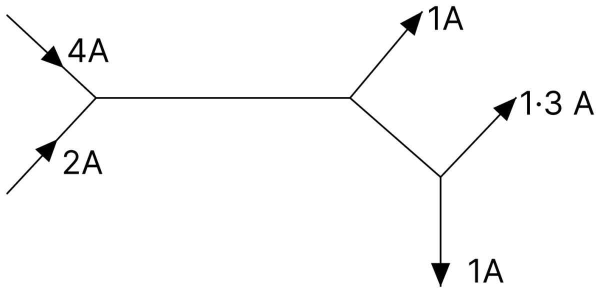
- 1.7 A
- 3.7 A
- 1.3 A
- 1.0 A
Answer
3.7 A
Reason — By Kirchhoff's junction rule the total current entering the network equals the total current leaving it.
Current entering = 4 A + 2 A = 6 A
Current leaving through the upper branch (1 A) and the 1.3 A branch = 1 A + 1.3 A = 2.3 A
Hence the current in the remaining branch is
Note: In the printed figure the downward branch at the lower junction, whose current is asked for, is labelled 1 A instead of I. Taking that branch as I gives the key value 3.7 A.
The resistivity of a potentiometer wire is 40 × 10-8 Ω m and area of cross-section is 8 × 10⁻⁶ m2. It carries a current of 0.2 A. The potential gradient (in volt/metre) along the wire is :
- 0.01
- 10
- 1.6 × 10⁻²
- 5
Answer
0.01
Reason — For a wire of length L, resistivity ρ and area of cross-section A, the resistance is R = ρL/A. If it carries a current I, the potential gradient along it is
Substituting I = 0.2 A, ρ = 40 × 10-8 Ω m and A = 8 × 10⁻⁶ m2,
The emf of a standard cell is balanced at 150 cm length of the wire of a potentiometer. When this cell is shunted by a wire of 2 Ω resistance, then the balance-point is obtained at a length of 100 cm. The internal resistance of the cell is :
- 0.1 Ω
- 1 Ω
- 2 Ω
- 0.5 Ω
Answer
1 Ω
Reason — In the potentiometer method for the internal resistance of a cell, if l1 is the balancing length for the emf of the cell and l2 the balancing length when the cell is shunted by a resistance R, then
Substituting R = 2 Ω, l1 = 150 cm and l2 = 100 cm,
In a potentiometer experiment, two cells are of emfs E1 and E2. The null deflection length on the potentiometer wire is obtained at 58 cm, when they are joined in series. If the polarity of emf E2 is reversed, then the null deflection is at 29 cm. The ratio of E1/E2 is :
- 3 : 1
- 2 : 1
- 1 : 3
- 1 : 2
Answer
3 : 1
Reason — When the two cells support each other the balancing length corresponds to (E1 + E2), and when E2 is reversed it corresponds to (E1 − E2). Since the balancing length is proportional to the emf,
Two cells of emfs approximately 5V and 10V are to be accurately compared using a potentiometer of length 400 cm.
- The battery that runs the potentiometer should have voltage of 8 V.
- The battery of potentiometer can have a voltage of 15 V and R adjusted so that the potential drop across the wire slightly exceeds 10 V.
- The first portion of 50 cm of wire itself should have a potential drop of 10 V.
- Potentiometer is usually used for comparing resistances and not voltages.
Answer
The battery of potentiometer can have a voltage of 15 V and R adjusted so that the potential drop across the wire slightly exceeds 10 V.
Reason — A balance point can be obtained on a potentiometer only if the potential difference across the whole wire is greater than the emf being measured. Here the larger emf is 10 V, so the potential drop across the wire must slightly exceed 10 V.
Sheetal had 6 identical cells, each of electromotive force (emf) 4V and internal resistance 'r'. She connected them to an external resistor 'R' in two different arrangements as shown and measured the current as 'I1' and 'I2' respectively.
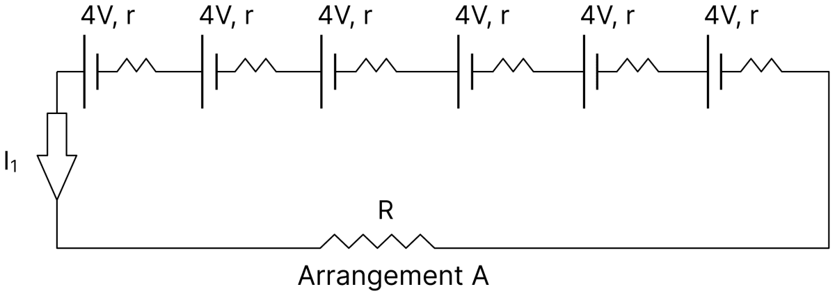
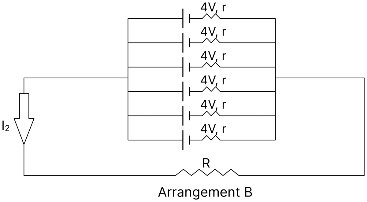
If 'I2' is found to be greater than 'I1' then which relation is true?
- R > r
- R = r
- R < r
- R = 6r
Answer
R < r
Reason — In Arrangement A the six cells are in series, so
In Arrangement B the six cells are in parallel, so
For I2 > I1,
In the meter bridge shown, the resistance X has a negative temperature coefficient of resistance. Neglecting the variation in other resistors, when current is passed for sometime in the circuit, balance point should shift towards :
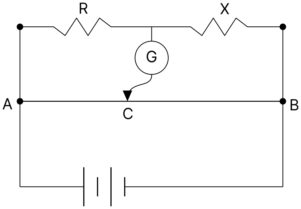
- A
- B
- It will remain at C
- Can't say because of incomplete information
Answer
B
Reason — For a negative temperature coefficient of resistance, the resistance decreases as the temperature rises. When current is passed for some time, X is heated by the current and its resistance falls.
If l is the balancing length measured from A, the balance condition of the meter bridge is
R remains unchanged while X decreases, so the ratio R/X increases. Hence l must increase, that is, the balance point shifts away from A and towards B.
In a Wheatstone bridge (see figure), resistances P and Q are approximately equal. When R = 400 Ω, the bridge is balanced. On interchanging P and Q, the value of R for balance is 405 Ω. The value of X is close to :
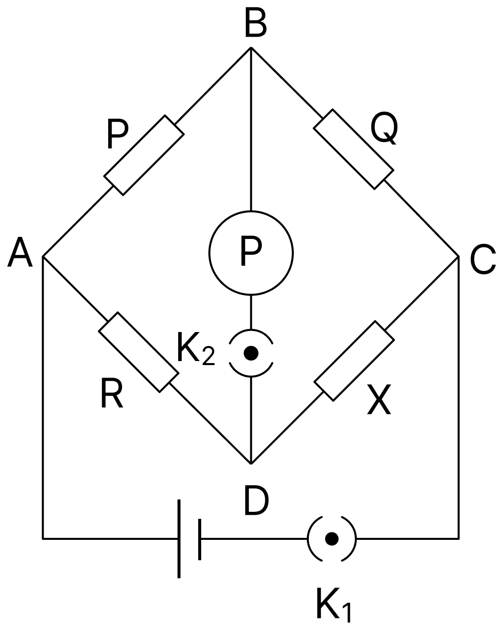
- 404.5 Ω
- 401.5 Ω
- 402.5 Ω
- 403.5 Ω
Answer
402.5 Ω
Reason — In the first case the condition of balance of the Wheatstone bridge gives
On interchanging P and Q the balance is obtained with R' = 405 Ω, so
Multiplying (i) and (ii),
The value of current I1 flowing from A to C in the circuit diagram is :
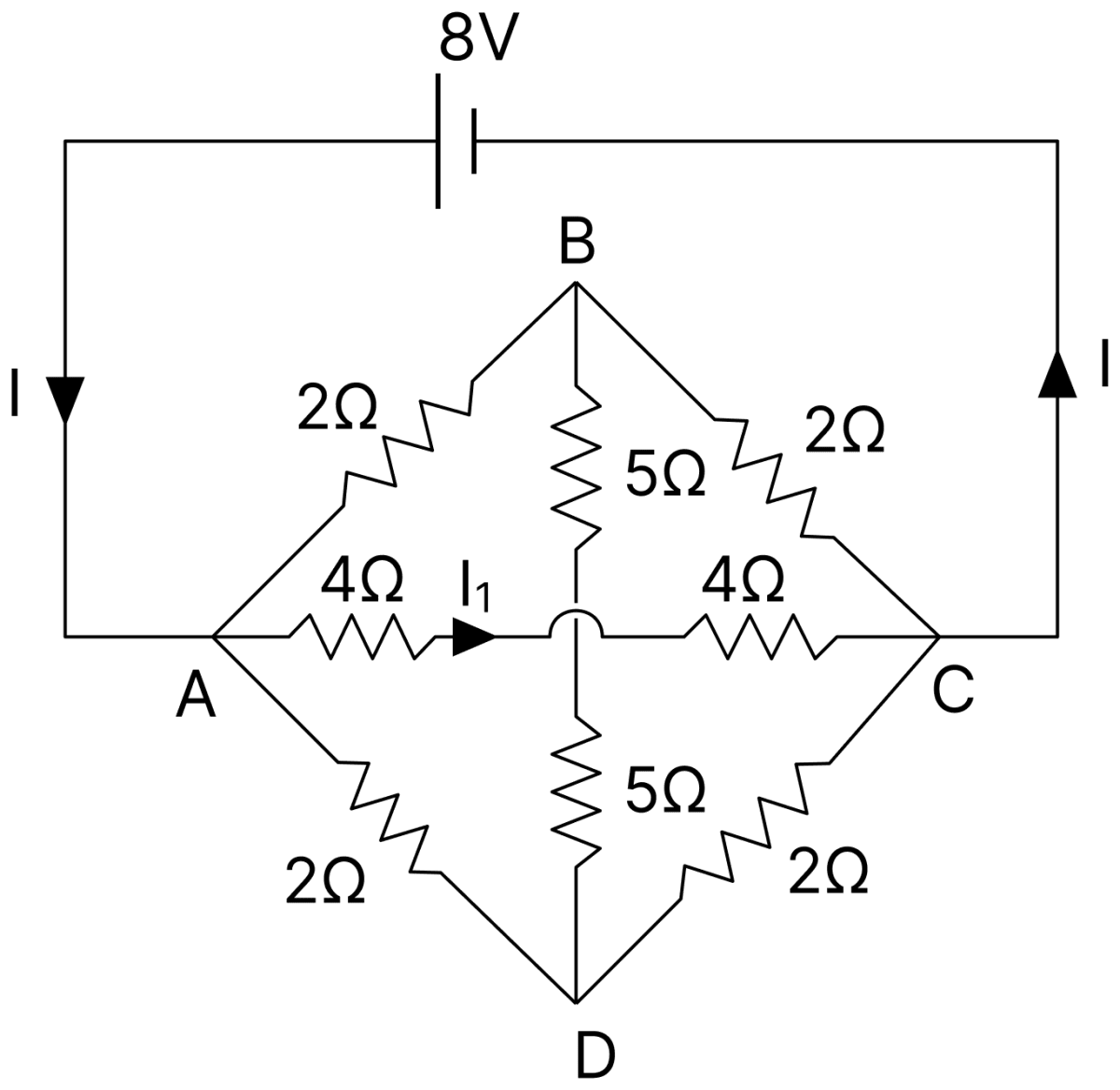
- 1 A
- 4 A
- 5 A
- 2 A
Answer
1 A
Reason — The network is symmetrical about the horizontal line AC. The upper branch A–B–C consists of 2 Ω and 2 Ω in series, and the lower branch consists of 2 Ω and 2 Ω in series, so B and D are both at the mid-potential between A and C. The junction of the two 4 Ω resistors is also at this same potential.
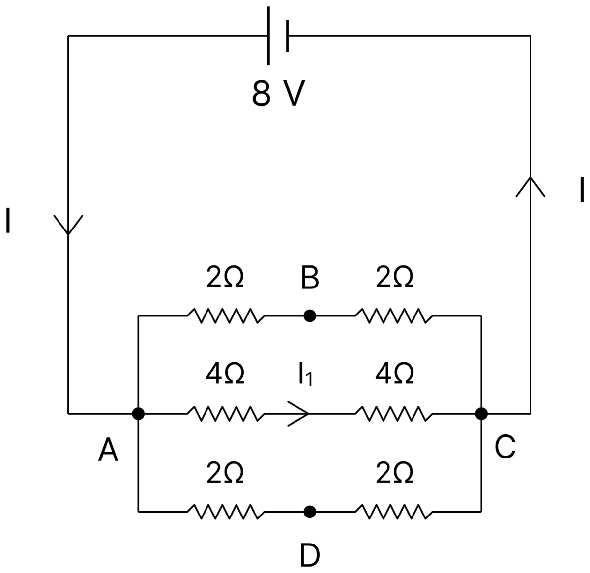
Hence there is no potential difference across either 5 Ω resistor and no current flows through them. The three paths from A to C are then
Upper branch : 2 + 2 = 4 Ω
Middle branch : 4 + 4 = 8 Ω
Lower branch : 2 + 2 = 4 Ω
The current I1 is the current in the middle branch, across which the potential difference is the full 8 V of the cell.
A constant-voltage supply is sending a constant current in a resistor. What is being dissipated in the circuit?
Answer
The electrical energy supplied by the constant-voltage supply is being dissipated as heat in the resistor.
Is internal resistance a drawback of the cell? Does it remain constant?
Answer
Yes, it is a drawback. No, it does not remain constant.
Explanation:
Owing to the internal resistance, some of the energy supplied by the cell is dissipated as heat within the cell, so the terminal potential difference is less than the emf. Further, the internal resistance gradually increases with use of the cell.
Name the two conservation laws implied in Kirchhoff's law for electric circuits.
Answer
Conservation of charge and conservation of energy.
Explanation:
Kirchhoff's first law (junction rule) follows from the conservation of charge, and the second law (loop rule) follows from the conservation of energy.
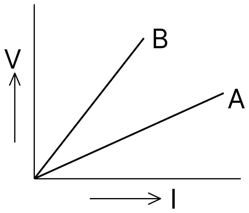
V-I graphs for series and parallel combinations of two metallic resistors are given. Which one represents parallel combination? Why?
Answer
The graph A represents the parallel combination.
The slope of a V–I graph gives the resistance of the combination. The graph A has the smaller slope, so it corresponds to the smaller resistance. Since the equivalent resistance of a parallel combination is smaller than that of a series combination of the same two resistors, A represents the parallel combination.
The lengths of three wires of same metal and same thickness are in the ratios 1 : 2 : 3. If we join them in parallel and then connect to a battery, what will be the ratios of currents in them? If wires are connected in series, then?
Answer
For wires of the same metal and the same area of cross-section, R ∝ l, so the resistances are in the ratio 1 : 2 : 3.
In parallel the potential difference across each wire is the same, and I = V/R, so the currents are in the inverse ratio of the resistances,
In parallel, the currents are in the ratio 6 : 3 : 2.
In series, the current in all the three wires will be the same.
In the last question, what will be the ratio of PD's across the three wires in the two cases?
Answer
In parallel, the ratio of the potential differences is 1 : 1 : 1, because all the three wires are connected between the same two points.
In series, the ratio is 1 : 2 : 3, because the current is the same in each wire and V = IR, so V ∝ R.
Write the unit of potential gradient in the wire of potentiometer. If potential gradient be reduced, will the balance point be obtained at a greater length or smaller length?
Answer
Volt/metre (or volt/cm); the balance point will be obtained at a greater length.
Explanation:
Since E = Kl, for a given emf the balancing length l is inversely proportional to the potential gradient K, so a smaller K gives a longer balancing length.
Why is a potentiometer preferred over a voltmeter in measuring the emf of a cell?
Answer
A voltmeter draws some current from the cell, so it measures the terminal potential difference and not the emf. In a potentiometer, at the balance point no current is drawn from the cell in the secondary circuit, so it measures the true emf of the cell.
A 10 m long potentiometer wire carries a steady current. A standard cell of emf 1.018 V is balanced against a length of 254.5 cm of the wire. What is the potential gradient across the potentiometer wire?
Answer
Given,
- Emf of the standard cell, E = 1.018 V
- Balancing length, l = 254.5 cm
At the balance point,
Hence, the potential gradient across the potentiometer wire is 4 × 10⁻³ V/cm = 0.4 V/m.
Name the device used for measuring the internal resistance of a secondary cell.
Answer
Potentiometer.
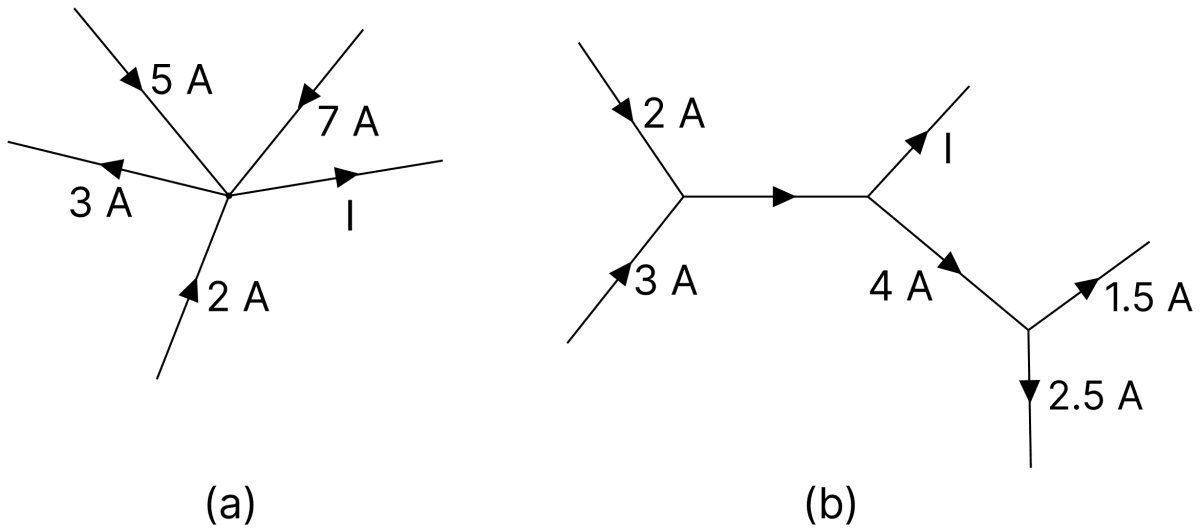
The figures show parts of electrical circuits. Compute I in each case.
Answer
By Kirchhoff's junction rule, the total current entering a junction is equal to the total current leaving it.
(a) At the junction, the currents of 5 A, 7 A and 2 A flow in and the current of 3 A flows out, along with I.
(b) At the first junction, 2 A and 3 A flow in, so the current in the joining branch is 2 + 3 = 5 A.
At the third junction, 1.5 A and 2.5 A flow out, so the current entering it is 1.5 + 2.5 = 4 A.
Applying the junction rule at the second junction, where 5 A enters and I together with 4 A leaves,
Hence, I = 11 A in (a) and I = 1 A in (b).
A wire of uniform cross-section and length l has a resistance of 16 Ω. It is cut into four equal parts. Each part is stretched uniformly to length l and all the four stretched parts are connected in parallel. Calculate the total resistance of this combination.
Answer
Given,
- Resistance of the whole wire = 16 Ω
- It is cut into 4 equal parts, and each part is stretched to the original length l
The resistance of each part before stretching is
Each part of length l/4 is stretched to length l, that is, its length becomes 4 times. On stretching, the volume remains constant, so R ∝ l2. Hence the resistance of each stretched part is
The four stretched parts are connected in parallel, so
Hence, the total resistance of the combination is 16 Ω.
A 4 Ω resistance wire is bent in the form of a circle. Find the effective resistance between the ends of a diameter.
Answer
Given,
- Resistance of the whole wire = 4 Ω
The ends of a diameter divide the circle into two equal semicircular halves, each of resistance
These two halves are connected in parallel between the ends of the diameter.
Hence, the effective resistance between the ends of a diameter is 1 Ω.
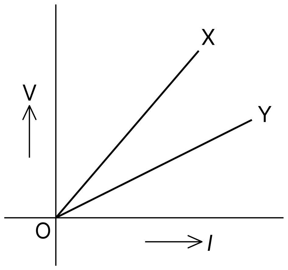
The figure shows the variation of potential difference V with length l of the wire for two potentiometers X and Y. Which one will you prefer for comparing emfs of two cells and why?
Answer
The potentiometer Y is preferred.
The slope of the V–l graph gives the potential gradient ΔV/Δl. The graph Y has the smaller slope, so its potential gradient is smaller. A smaller potential gradient gives a longer balancing length for the same emf, which makes the measurement more sensitive and hence more accurate.
Does emf of a cell represent a force or potential energy or work done per unit charge? When will it be equal to the PD across the terminals of the cell?
Answer
The emf of a cell represents the work done per unit charge. It is equal to the terminal potential difference when the cell is in open circuit (no current drawn).
Explanation:
The emf is the work done by the cell in forcing unit positive-charge to flow round the whole circuit, including the cell itself,
In spite of its name, emf is not a force at all; its unit is joule/coulomb, that is, volt.
When no current is drawn from the cell, there is no potential drop Ir inside the cell, so V = E.
What is internal resistance of a cell? On what factors does it depend?
Answer
Internal resistance : The resistance which the electrolyte between the plates offers to the flow of ions inside a cell is called the internal resistance of the cell. Some of the energy supplied by the cell is dissipated as heat in this resistance.
The internal resistance of a cell depends upon :
(i) the separation between the two plates — it is directly proportional to this separation;
(ii) the area of the plates dipped into the electrolyte — it is inversely proportional to this area;
(iii) the nature, concentration and temperature of the electrolyte — it increases with increase in concentration and decreases with increase in temperature.
It is easier to start a car engine on a warm day than on a cold day. Why?
Answer
The internal resistance of a cell decreases with increase in the temperature of the electrolyte. Hence on a warm day the internal resistance of the car battery is less than on a cold day.
Since the current drawn is I = E/(R + r), a smaller internal resistance allows a larger current to be drawn from the battery, and this larger current starts the engine more easily.
When the external resistance R connected in series with a cell is exactly halved, the current is not exactly doubled. Why?
Answer
This happens because of the internal resistance r of the cell. The current drawn from the cell is
When R is halved the current becomes
The denominator is reduced from (R + r) to (R/2 + r), which is more than half of (R + r) because r is unchanged. Hence I' is slightly less than 2I.
On increasing the current drawn from a cell, the PD across the cell terminals is further lowered. Why?
Answer
This happens because of the internal resistance r of the cell. The terminal potential difference is
The emf E and the internal resistance r of the cell are fixed, so as the current I drawn from the cell is increased, the potential drop Ir inside the cell increases and V is lowered further.
Can a cell (emf E, internal resistance r) have zero terminal PD? Under what condition?
Answer
Yes. The terminal potential difference of the cell becomes zero when the cell is short-circuited, that is, when the external resistance R = 0.
Explanation:
In this condition the maximum current is drawn from the cell,
Therefore,
The car-battery is of 12 V. 8 simple cells connected in series can give 12 V. But such cells are not used in starting a car, why?
Answer
Starting a car needs a very heavy current, and the current that a battery can supply is limited by its internal resistance.
The internal resistance of 8 simple cells joined in series is of the order of 10 Ω, whereas that of a car-battery is only of the order of 0.1 Ω. Hence the simple cells cannot supply the heavy current required to start the car, even though their net emf is also 12 V.
When a motor car is started then its head-light becomes slightly dim, why?
Answer
When the motor car is started, the starter draws a heavy current from the car-battery. Because of this large current the potential drop Ir inside the battery increases appreciably, so the potential difference between the plates of the battery falls.
The head-light is connected across the same terminals, so the potential difference across it also falls and it becomes dim.
When a high-power heater is connected to electric mains, the bulbs lightening in the house become dim, why?
Answer
The heater draws a heavy current from the mains. Because of this large current there is an appreciable potential-drop in the line wires, which have a small but finite resistance.
As a result the potential difference available across the bulbs falls and they become dim.
State Kirchhoff's first law (junction rule) and prove that it is simply a statement of the conservation of charge.
Answer
Kirchhoff's first law (junction rule) : The algebraic sum of the currents meeting at a junction in an electric circuit is zero, that is, the total current flowing towards a junction is equal to the total current flowing away from it.
Proof : Charge cannot accumulate at a junction, because a junction is merely a point of the circuit and has no capacity to store charge. Hence in any time interval dt the charge arriving at the junction must equal the charge leaving it.
If the currents I1 and I2 flow towards a junction and I3 and I4 flow away from it, then in time dt,
Thus the junction rule is simply a statement of the conservation of charge.
State Kirchhoff's second law (loop rule) as a mathematical equation, mentioning what the symbols used stand for.
Answer
Kirchhoff's second law (loop rule) : In any closed loop of an electric circuit, the algebraic sum of the emfs is equal to the algebraic sum of the products of the currents and the resistances in that loop.
Here,
E is the emf of a cell in the loop, taken positive when the loop is traversed from the negative to the positive electrode of the cell and negative otherwise,
I is the current in a resistance of the loop, and
R is that resistance, the product IR being taken positive when the loop is traversed in the direction of the current and negative otherwise.
This law is a statement of the conservation of energy.
State the relation among the resistances of the arms of a balanced Wheatstone's bridge.
Answer
Explanation:
In a Wheatstone bridge ABCD with P = AB, Q = BC, R = AD and S = DC, a cell across AC and a galvanometer across BD, the bridge is balanced when the above relation holds. In this condition no current flows through the galvanometer.
What is meant by the sensitivity of a potentiometer? How can it be increased?
Answer
Sensitivity : A potentiometer is said to be sensitive if, on displacing the jockey slightly from the null point, the galvanometer shows a large deflection. The smaller the potential gradient, the greater the sensitivity.
The sensitivity of a potentiometer is increased by decreasing its potential gradient, since
where I is the current in the wire, R its resistance and L its length.
This can be done in two ways :
(i) by increasing the length of the potentiometer wire, and
(ii) by decreasing the current in the potentiometer wire, using a rheostat in the primary circuit.
How will the position of balance point in potentiometer be affected if, (i) the emf to be measured be smaller, (ii) the current in the potentiometer wire be decreased, (iii) the length of the potentiometer wire be doubled?
Answer
At the balance point E = Kl, so the balancing length is l = E/K.
(i) If the emf to be measured is smaller, the balance point will be obtained at a smaller length of the wire.
(ii) If the current in the potentiometer wire is decreased, the potential gradient K decreases, so the balance point will be obtained at a larger length of the wire.
(iii) If the length of the wire is doubled, the potential difference across the whole wire remaining the same, the potential gradient is halved, so the balance point will be obtained at twice the previous length.
Why is a copper wire not used in potentiometer?
Answer
The specific resistance of copper is small and its temperature-coefficient of resistance is large.
Because of its small specific resistance, a copper wire has a very small resistance, so the potential difference across the whole wire is very small (it may be less than the emf to be measured, and then no null point is obtained) and a large current flows, heating the wire. Further, a large temperature-coefficient makes the resistance of the wire change as the current heats it, so the potential gradient does not remain constant. For these reasons copper is not used, and wires of manganin or constantan are used instead.
The given network has two cells of emfs E1 and E2, and two resistances R1 and R2. The ammeter A reads zero. What would the voltmeter V read?
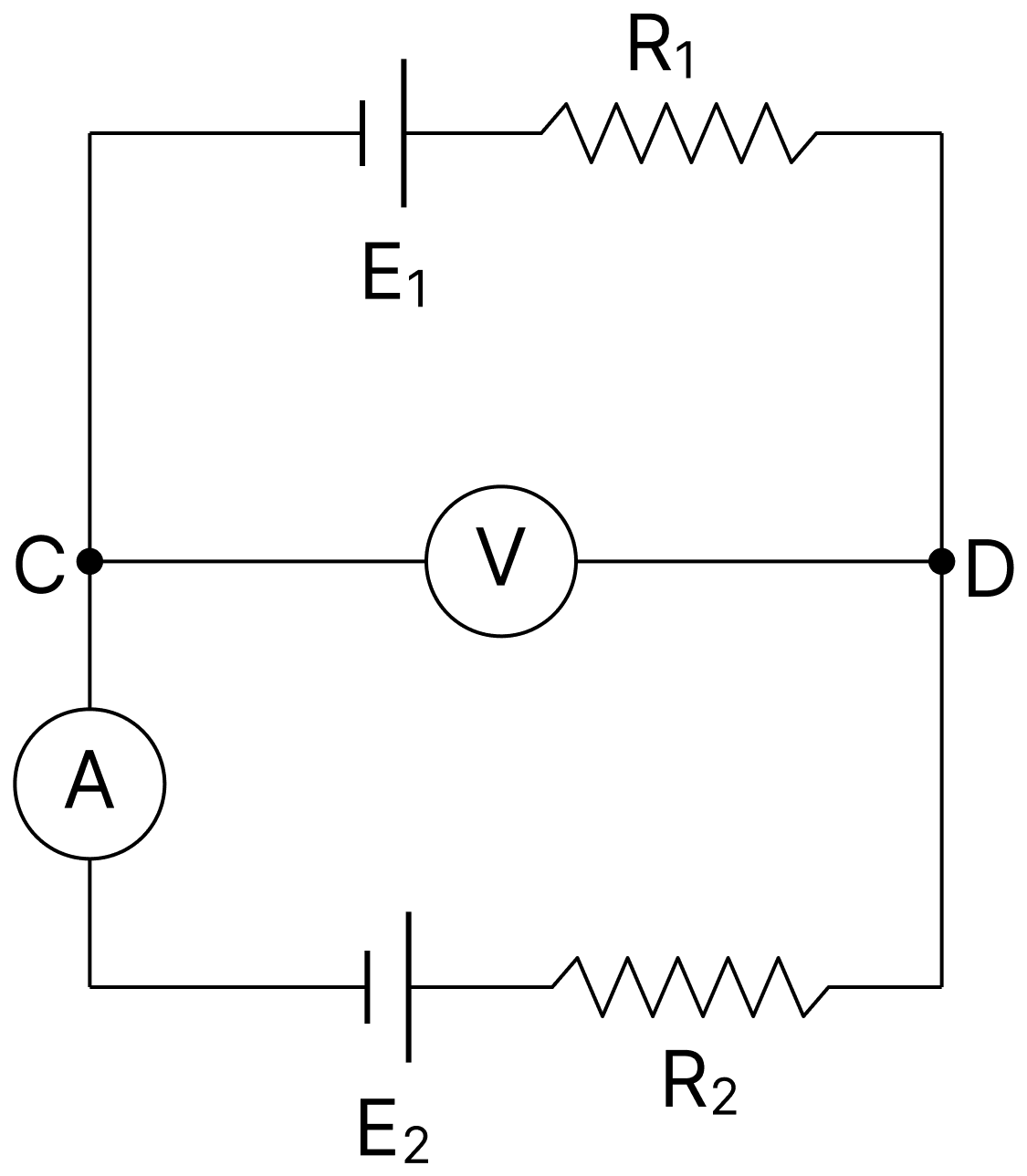
Answer
The voltmeter will read the emf E2 of the lower cell.
Explanation:
Since the ammeter reads zero, no current flows in the branch containing E2 and R2. Hence there is no potential drop across R2 or across the internal resistance of the cell, and the potential difference between C and D is equal to the emf E2.
Find the emf and the internal resistance of an electric source which is equivalent to two batteries of emf's E1 and E2 and internal resistances r1 and r2 connected in parallel.
Answer
Let E be the emf and r the internal resistance of the equivalent source.
Since the two batteries are connected in parallel, their internal resistances are in parallel,
The maximum currents that can be drawn from the two batteries are E1/r1 and E2/r2, so the total current is
If the same current I is drawn from the equivalent source, its emf is
If the resistance R in the circuit is increased, what will be the effect on the reading of the ammeter A, when the internal resistance r of the cell is (a) negligible, (b) not negligible.
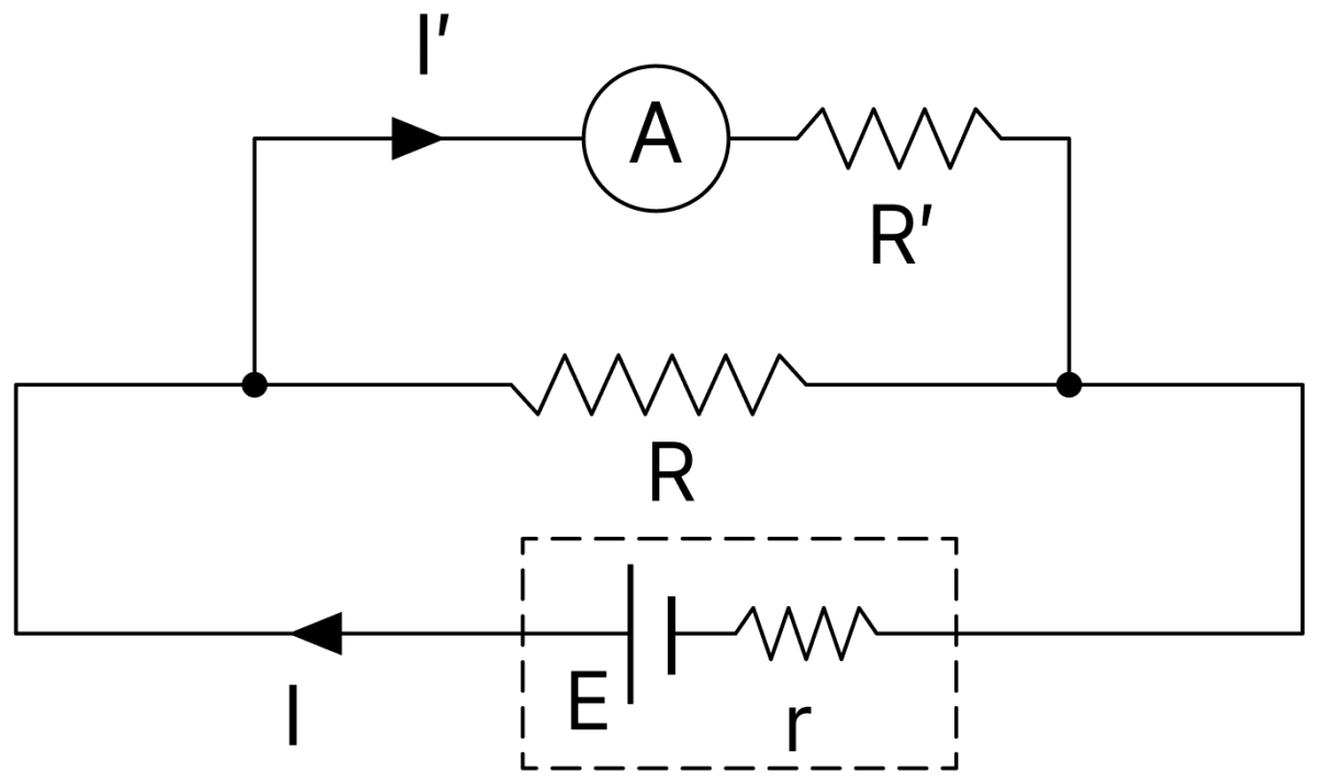
Answer
The resistances R and R' are in parallel across the cell, so the current drawn from the cell is
The current through the ammeter, that is, through R', is
(a) If r is negligible, Eq. (i) gives I' = E/R', which does not contain R at all. Hence there will be no effect on the reading of the ammeter on increasing R.
(b) If r is not negligible, then on increasing R the term r(1 + R'/R) in the denominator of Eq. (i) decreases, so the current I' will increase.
Up to what voltage will the capacitor C in the diagram below be charged? Internal resistance of the cell E is negligible.
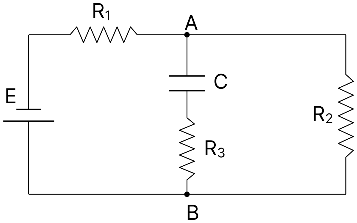
Answer
After the capacitor C is fully charged, the current in the branch containing C and R3 stops, and a steady current flows only through R1 and R2.
Since there is now no current in R3, there is no potential difference across it. Hence the potential difference between the plates of C is the same as that between A and B, that is, the potential difference across R2.
The current in R1 and R2 is
Therefore the potential difference across R2, and hence across C, is
Determine the potentials at points A and B in the given circuit, assuming earth at zero potential.
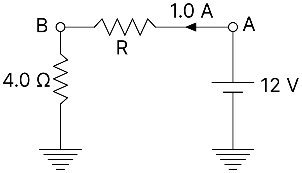
Answer
Given,
- Emf of the cell = 12 V, negative terminal earthed, positive terminal at A
- Current from A through R and the 4.0 Ω resistor = 1.0 A
- Lower end of the 4.0 Ω resistor earthed (zero potential)
The 12 V cell has its lower end earthed, and the earth is at zero potential. Hence the potential at the point A is
A current of 1.0 A flows through the 4.0 Ω resistor, so the potential drop across it is
The lower end of the 4.0 Ω resistor is earthed and is therefore at zero potential. Hence the potential at its upper end B is
Hence, the potential at A is 12 V and that at B is 4 V.
Compute in the given circuit the potentials of points A and D terminal and terminal voltage across the 10 V cell.
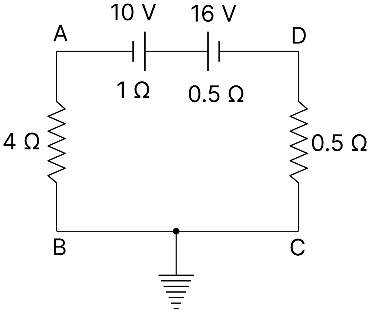
Answer
Given,
- E1 = 10 V, r1 = 1 Ω; E2 = 16 V, r2 = 0.5 Ω (cells opposing)
- Resistances 4 Ω (AB) and 0.5 Ω (DC)
- The wire BC is earthed (zero potential)
The two cells oppose each other, so the net emf driving the current is 16 V − 10 V = 6 V, and the total resistance of the loop is
The point between B and C is earthed, so it is at zero potential.
Potential at A : The 4 Ω resistor lies between A and the earthed point, and the potential drop across it is 1 × 4 = 4 V. Hence
Potential at D : The 0.5 Ω resistor lies between D and the earthed point, and the potential drop across it is 1 × 0.5 = 0.5 V. Since the current flows from the earthed point towards D through this resistor, D is at a lower potential,
Terminal voltage across the 10 V cell : The current enters this cell at its positive electrode, so the cell is being charged. Its terminal voltage is
Hence, VA = 4 V, VD = − 0.5 V and the terminal voltage across the 10 V cell is 11 V.
A set of n identical resistors, each of resistance R Ω, when connected in series have an effective resistance X ohm and when the resistors are connected in parallel, their effective resistance is Y Ω. Find the relation between R, X and Y.
Answer
When the n identical resistors are connected in series,
When they are connected in parallel,
Multiplying Eqs. (i) and (ii),
The student sets up an experiment in the lab to determine the internal resistance of a cell by graphical method. The setup of the circuit is done as shown below using a cell of emf. 'E' and internal resistance 'r', a variable resistor 'R' and a milliammeter. A voltmeter 'V' is connected to the circuit as shown.
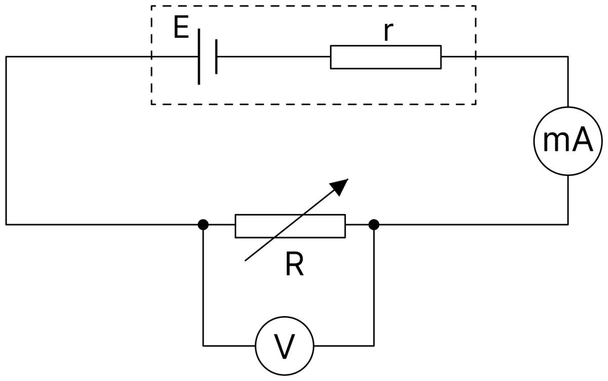
(a) Draw the nature of the graph so determined. What does the Y-intercept of the graph represent?
(b) How can internal resistance be calculated from the graph?
Answer
(a) The terminal potential difference is V = E − Ir, so the graph of V against I is a straight line of negative slope.
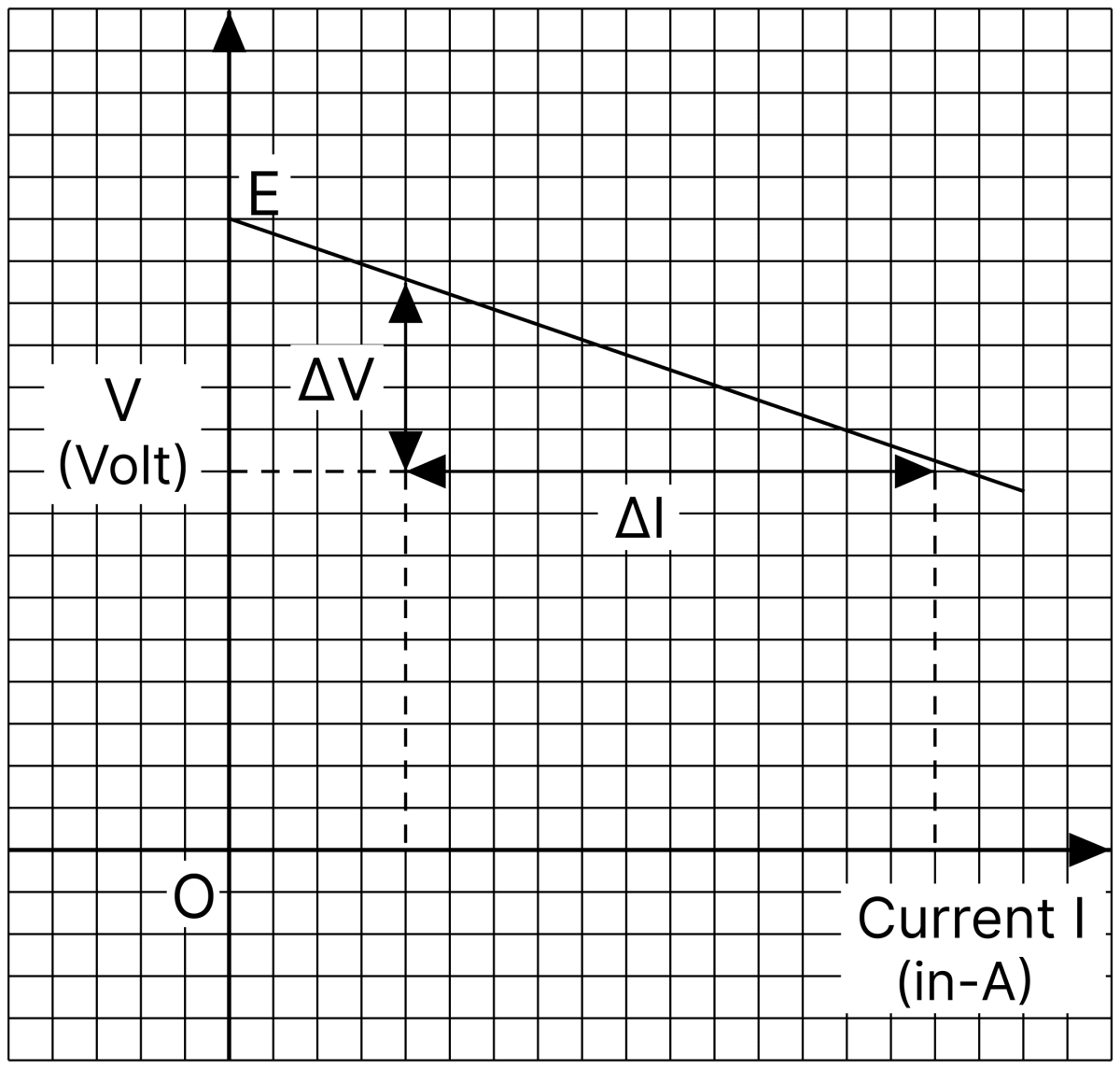
The Y-intercept of the graph gives the emf E of the cell, since V = E when I = 0.
(b) Comparing V = E − Ir with y = mx + c, the magnitude of the slope of the graph gives the internal resistance,
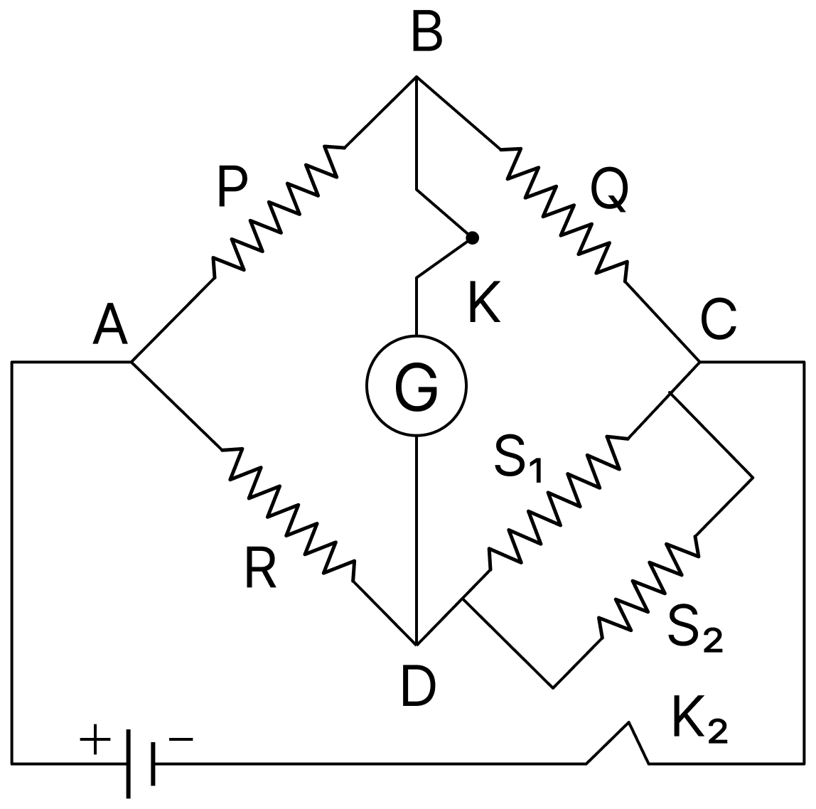
In a Wheatstone bridge, three resistances P, Q and R are connected in the three arms, and the fourth arm is formed by two resistances S1 and S2 connected in parallel. Evaluate the new condition for the bridge to be balanced.
Answer
The resistance of the fourth arm is the equivalent resistance of S1 and S2 in parallel,
Substituting this in the condition of balance of the Wheatstone bridge, P/Q = R/S,
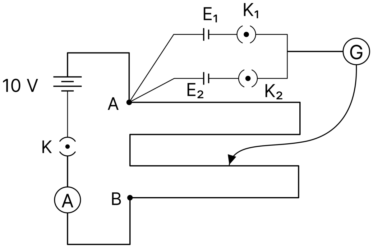
Two cells of electromotive forces (emfs) approximately 5 V and 10 V are to be accurately compared using a potentiometer of length 400 cm. The student sets up the circuit as shown in the diagram. However, he is not able to measure the ratio of emfs correctly. Analyse the circuit shown and spot a minimum of two errors in the circuit. Explain with proper reasoning.
Answer
The errors in the circuit are :
(i) The emf of the driver battery is only 10 V. It must be greater than 10 V, so that the potential difference across the wire is more than the emfs of the cells to be compared. Otherwise the balance length for the 10 V cell cannot be determined at all.
(ii) There is no rheostat in the primary circuit. A series variable resistance must be added to the primary circuit, so that the current drawn from the driver cell can be reduced and the potential drop across the potentiometer wire adjusted.
(iii) Both the keys K1 and K2 are shown closed. At a time only one key should be closed and the other must be kept open, so that only one cell is included in the secondary circuit while its balance point is being found.
What is an electric cell? Define emf of a cell. On what factors does the emf of a cell depend?
Answer
Electric cell : An electric cell is a source of electrical energy which maintains a continuous flow of charge in a circuit. It consists of two rods of different metals, called 'electrodes' or 'plates', immersed in a liquid called 'electrolyte'.
A chemical reaction takes place in the electrolyte of the cell as a result of which positive and negative ions are generated. These move to the electrodes and maintain the supply of charge to them. When the two plates are connected by a wire, the charge begins to flow in the wire. Thus, the cell changes chemical energy into electrical energy.
Emf of a cell : The work done by the cell in forcing unit positive-charge to flow in the whole circuit (including the cell) is called the 'electromotive force' (emf) of the cell.
Its unit is joule/coulomb, which is called 'volt'. If in the flow of 1 C of charge in a circuit the work done by the cell be 1 J, then the emf of the cell is 1 V.
Factors on which the emf depends : The emf is a characteristic of the cell which depends upon the nature of the plates and the nature of the electrolyte used in the cell. It does not depend upon the dimensions of the electrodes, their separation or the quantity of electrolyte.
Define the emf of a cell in terms of the work done in moving a charge through the cell. Using Joule's law obtain the equation, emf = I (R + r).
Answer
Emf : If dW is the work done by the cell in forcing a charge dq from its negative to its positive electrode, then the emf of the cell is
Derivation : Let a cell of emf E and internal resistance r be connected to an external resistance R, and let a steady current I be established in the circuit. In time dt the charge that flows is dq = I dt, so the work done by the cell is
This energy is consumed as heat in the external resistance R and in the internal resistance r. By Joule's law, the heat produced in time dt is
By the conservation of energy,
Dividing throughout by I dt,
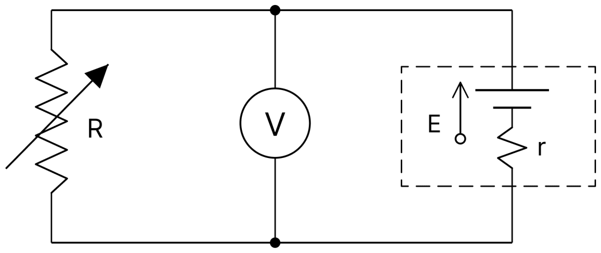
The given figure shows a cell of emf E and internal resistance r, connected to a voltmeter V and a variable resistance R. Deduce the relationship among V, E, R and r. How will V vary when R is reduced?
Answer
The current drawn from the cell is
The voltmeter reads the terminal potential difference, which is the potential drop across R,
or,
The relation may also be written as
Variation of V : As R is reduced, the ratio r/R increases, so the denominator in the expression for V increases. Hence V will decrease when R is reduced.
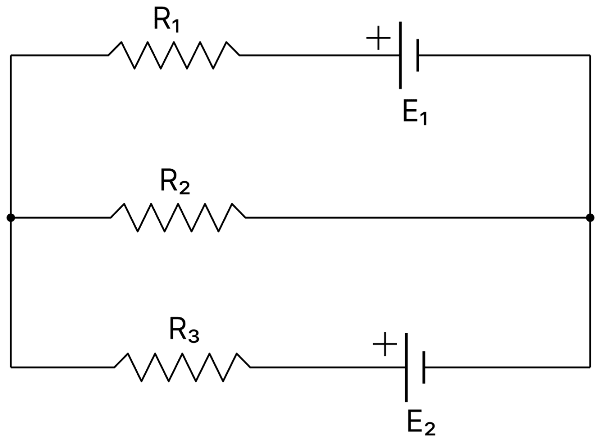
State and explain Kirchhoff's laws for electric circuits. What are the conservation laws implied in each law? State the sign convention for current and emf. Use the given circuit for your explanation.
Answer
First law (junction rule) : The algebraic sum of the currents meeting at a junction in an electric circuit is zero,
That is, the total current arriving at a junction is equal to the total current leaving it. Since charge cannot accumulate at a junction, this law is a statement of the conservation of charge.
Second law (loop rule) : In any closed loop of an electric circuit, the algebraic sum of the emfs is equal to the algebraic sum of the products of the currents and the resistances in that loop,
As one goes round a closed loop and returns to the starting point, the total change of potential must be zero. Hence this law is a statement of the conservation of energy.
Sign convention :
(i) A current flowing towards a junction is taken as positive and one flowing away from it as negative.
(ii) While traversing a loop, the product IR is taken as positive if the loop is traversed in the direction of the current, and negative if traversed against it.
(iii) The emf E of a cell is taken as positive if the loop is traversed from its negative electrode to its positive electrode inside the cell, and negative otherwise.
Application to the given circuit : In the circuit shown, R1 and the cell E1 form one branch, R2 forms a second branch, and R3 with the cell E2 forms a third branch, all joined between the same two junctions.
Applying the junction rule at one junction gives the relation among the three branch currents. Applying the loop rule to the closed loop containing R1, E1 and R2, and again to the loop containing R2, R3 and E2, gives two more equations. These three equations are then solved for the unknown currents.
n identical cells, each of emf E and internal resistance r, are connected in series to a resistor R. Deduce an expression for the internal resistance r of one cell in terms of the current I in the circuit.
Answer
When n identical cells are joined in series, the net emf is nE and the total internal resistance is nr. Hence the current in the circuit is
Obtain the relation R1/R2 = R3/R4 for a Wheatstone's bridge. The symbols have their standard meanings.
Answer
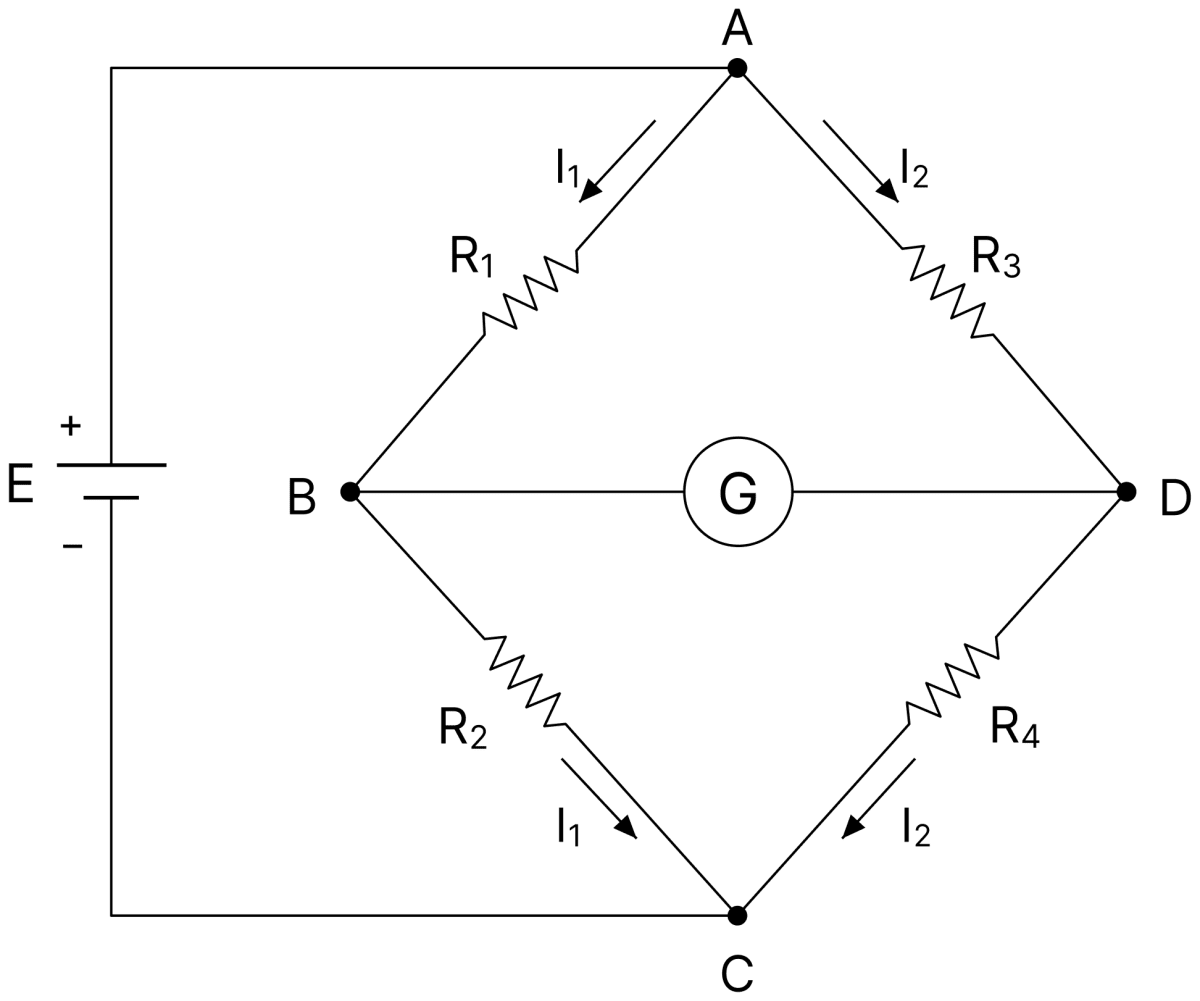
Four resistances R1, R2, R3 and R4 are connected in the four arms of the bridge (R1 = AB, R2 = BC, R3 = AD, R4 = DC), with a cell E across AC and a galvanometer G across BD.
The bridge is said to be balanced when the galvanometer shows no deflection. In this condition no current flows through the galvanometer, so the points B and D are at the same potential.
Let the current I1 flow through R1 and R2, and the current I2 through R3 and R4. Since the potentials at the two ends of the galvanometer are equal, the potential drops across R1 and R3 must be equal, and so must those across R2 and R4.
Dividing Eq. (i) by Eq. (ii),
This is the required condition of balance of the Wheatstone bridge.
State the principle of working of Wheatstone bridge. With the help of a circuit diagram, explain how it is used in the determination of the specific resistance of the material of a wire using meter bridge.
Answer
Principle : When four resistances are connected in the four arms of a Wheatstone bridge, with a cell across one diagonal and a galvanometer across the other, the bridge is balanced and the galvanometer shows no deflection when
Meter bridge : The meter bridge is the practical form of the Wheatstone bridge.
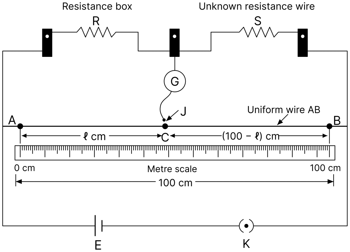
A uniform wire AB of length 100 cm is stretched along a metre scale and its ends are joined to two L-shaped copper strips. A resistance box R is connected in the left gap and the wire S of unknown resistance in the right gap. A cell with a key is connected across AB, and a galvanometer is joined between the central strip and a jockey which can slide along the wire.
A suitable resistance R is taken out from the box and the jockey is moved along the wire until the galvanometer shows no deflection. Let the balance point be at a distance l cm from A. Then the resistances of the two parts of the wire are proportional to their lengths, so
Specific resistance : The length L of the given wire is measured with a metre scale and its diameter d is measured with a screw gauge, so that its area of cross-section is
Since S = ρL/a, the specific resistance of the material of the wire is
Explain with diagram, the principle of a potentiometer. How can its sensitivity be increased? Why is it superior to a voltmeter?
Answer
Principle : When a constant current is passed through a wire of uniform cross-section, the potential difference across any portion of the wire is directly proportional to the length of that portion (V = Kl).
A potentiometer consists of a long uniform wire AB of high specific resistance and low temperature-coefficient of resistance, stretched on a wooden board.
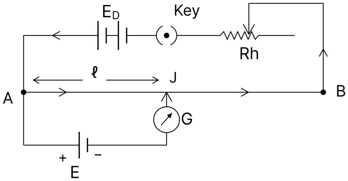
A driving cell of emf ED is connected across the ends of the wire through a rheostat, so that a steady current flows through it and a constant potential gradient is set up along its length.
If K is the potential gradient and the balance point for a cell of emf E in the secondary circuit is obtained at a length l from A, then the potential difference across this length is Kl. At balance no current flows through the galvanometer, so
Thus the emf of a cell is directly proportional to the balancing length of the potentiometer wire.
Sensitivity : The sensitivity is increased by decreasing the potential gradient K = IR/L (where I is the current in the wire, R its resistance and L its length), that is, by increasing the length of the wire or by decreasing the current in it with the help of the rheostat.
Superiority over a voltmeter : A voltmeter draws some current from the cell whose emf is to be measured, so it always reads the terminal potential difference, which is less than the emf. In a potentiometer no current is drawn from the cell at the balance point, so it measures the true emf. A potentiometer therefore behaves like an ideal voltmeter of infinite resistance.
Draw a labelled circuit diagram of a potentiometer to compare emf's of two cells. Write the working formula (Derivation not required).
Answer
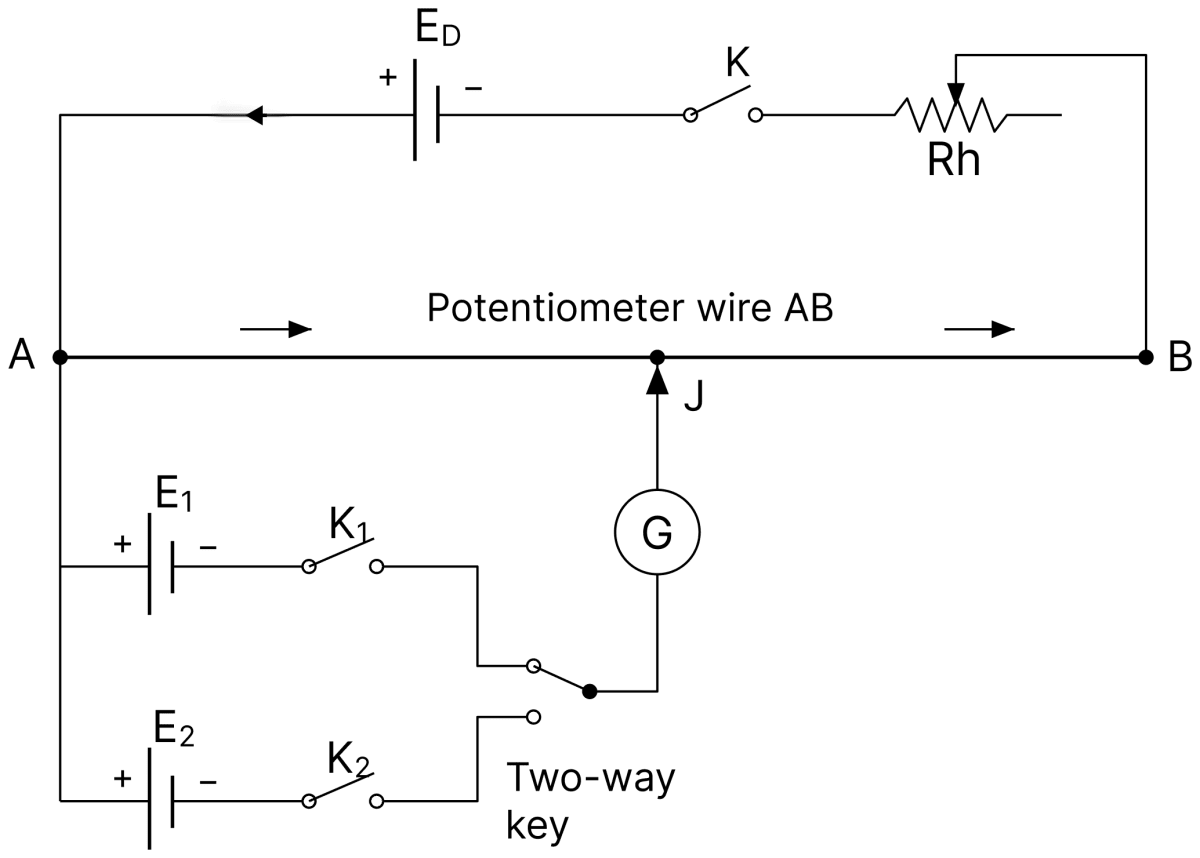
The potentiometer wire AB is connected to the driving cell ED through a key and a rheostat, forming the primary circuit. The positive terminals of the two cells E1 and E2 are joined to the end A, and their negative terminals are taken through the keys K1 and K2 to a two-way key, and then through the galvanometer to the jockey J.
With the two-way key connecting E1 (K1 closed, K2 open), the balance point is obtained at a length l1 from A. Then, with the two-way key connecting E2 (K2 closed, K1 open), the balance point is obtained at a length l2.
Working formula :
Draw a labelled circuit diagram of a potentiometer to measure internal resistance of a cell. Write the working formula. (Derivation not required).
Answer
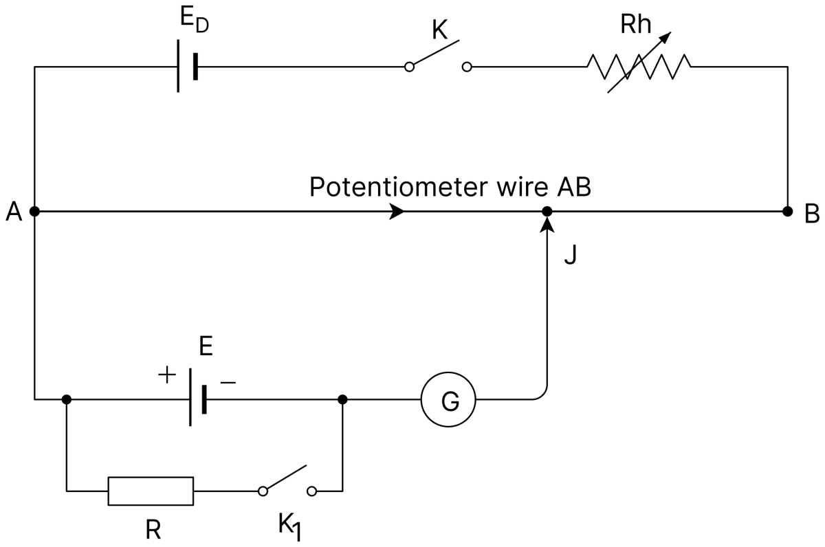
The potentiometer wire AB is connected to the driving cell ED through a key and a rheostat. The cell of emf E whose internal resistance is to be found is connected between A and the jockey through a galvanometer, and a resistance box R with a key K1 is connected across this cell.
With the key K1 open, the balance point is obtained at a length l1 from A, which corresponds to the emf E of the cell. A resistance R is then introduced and K1 closed, and the new balance point is obtained at a length l2, which corresponds to the terminal potential difference V.
Working formula :
An experiment on meter bridge is performed by a student. The examiner gives the requisite instructions and asks some questions to the student. State whether the responses of the student in each case are correct or incorrect. Give a reason for each.
(i) EXAMINER : On which principle, working of meter bridge is based?
STUDENT : It is based on principle of balanced Wheatstone bridge.
(ii) EXAMINER : The resistance in the given gap of meter bridge is high. Decrease its value.
STUDENT : Uses a thicker wire of same length in place of the existing wire in the gap.
(iii) EXAMINER : Null-point is at 75.0 cm on right hand side of the 1m length wire of the meter bridge bench. Resistance box is in the left gap. Shift the null-point towards the left side of the wire.
STUDENT : Increases the resistance introduced through resistance box.
Answer
(i) The response of the student is correct. The meter bridge is the practical form of the Wheatstone bridge, and the unknown resistance is found from the condition of balance of the Wheatstone bridge.
(ii) The response of the student is correct. The resistance of a wire is
For the same length and the same material, R is inversely proportional to the area of cross-section. Hence a thicker wire has a smaller resistance.
(iii) The response of the student is incorrect. For the meter bridge,
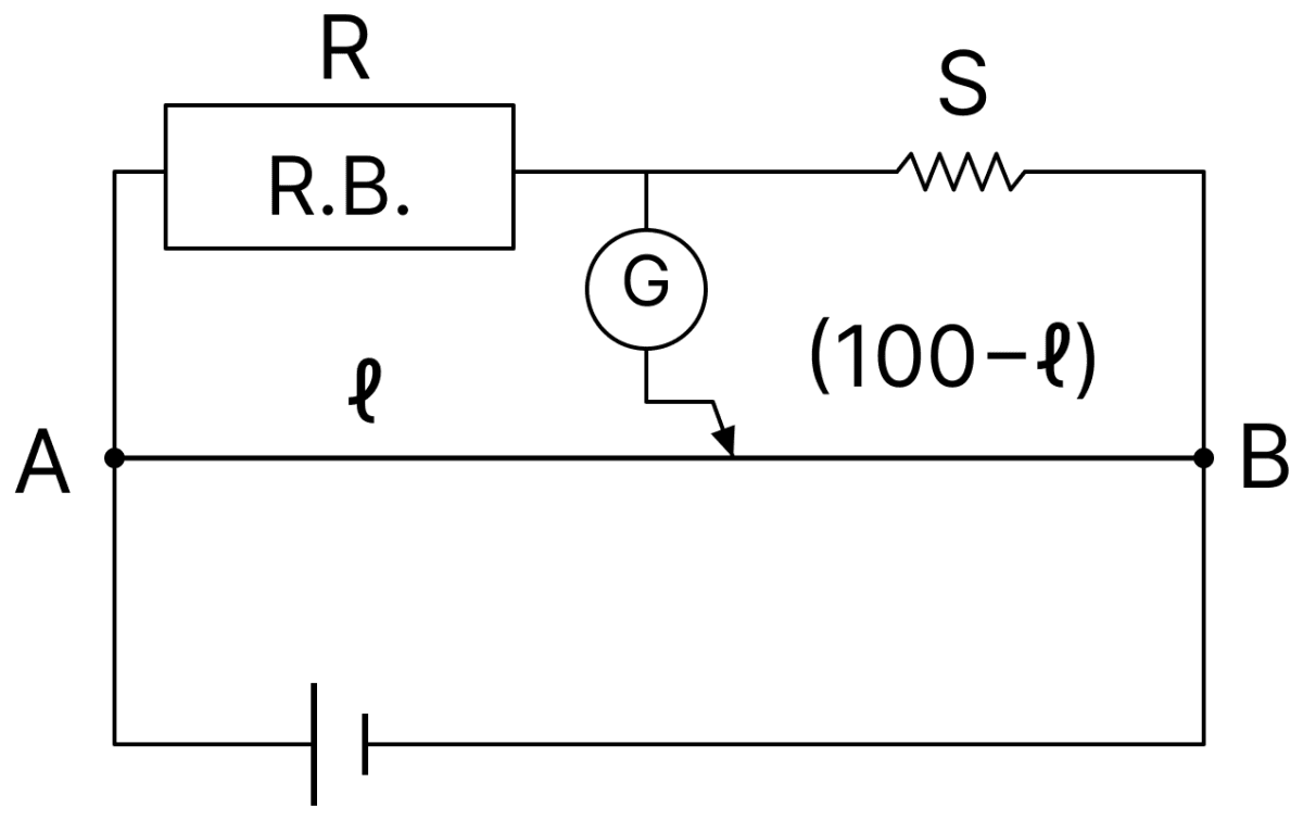
To shift the null-point towards the left, l must decrease, and for this the ratio R/S must decrease. Since S is fixed, R must be decreased and not increased.
Define emf of a cell and its terminal potential difference. Show that emf of cell is greater than terminal potential difference, when current is with-drawn and emf is lesser when cell is being charged.
Answer
Emf : The work done by the cell in forcing unit positive-charge to flow in the whole circuit, including the cell itself, is called the electromotive force (emf) of the cell.
Terminal potential difference : The work done in carrying unit positive-charge through the external circuit, from one terminal of the cell to the other, is called the terminal potential difference of the cell.
When current is withdrawn from the cell : Let a cell of emf E and internal resistance r send a current I through an external resistance R. Then
The terminal potential difference is V = IR, so
Since Ir is a positive quantity, V is less than E. Thus the emf of a cell is greater than its terminal potential difference when current is drawn from it.
Physically, a part of the energy given by the cell is consumed in driving the current through the internal resistance of the cell itself.
When the cell is being charged : During charging, the current is sent into the cell from an external source and flows inside the cell from the positive to the negative electrode, that is, opposite to the direction in which the cell itself would drive it. Now the potential drop Ir is added to the emf, and
Hence V is greater than E. Thus the emf of a cell is less than its terminal potential difference when the cell is being charged.
n cells each of emf E and internal resistance r are connected in series to form a row. m such rows are connected in parallel to form a battery of N = mn cells. This battery is connected to an external resistance R. (i) What is the emf of this battery and how much is its internal resistance? (ii) Show that current I flowing through the external resistance R is given by
Answer
(i) Emf and internal resistance of the battery :
In each row the n cells are joined in series, so the emf of one row is nE and its internal resistance is nr.
The m rows are joined in parallel, and all of them have the same emf. Hence the emf of the whole battery is
The internal resistances of the m rows, each equal to nr, are in parallel, so the internal resistance of the battery is
(ii) Current through R :
Since N = mn,
Write the principle of potentiometer, draw its circuit diagram. How its sensitivity can be increased? Why it is called as ideal voltmeter? Describe, how internal resistance of a cell can be determined using potentiometer.
Answer
Principle : When a steady current flows through a uniform wire of a potentiometer, a constant potential gradient K is set up along its length. If the balance point for a cell of emf E is obtained at a length l, then
that is, the emf of the cell is directly proportional to the balancing length.
In this figure B1 is the driving battery, which sends a steady current through the potentiometer wire AB.
Sensitivity : The sensitivity is increased by decreasing the potential gradient K = IR/L (where I is the current in the wire, R its resistance and L its length), either by increasing the length of the potentiometer wire or by decreasing the current in it by means of a rheostat in the primary circuit.
Why it is called an ideal voltmeter : At the balance point the galvanometer shows no deflection, so no current is drawn from the cell in the secondary circuit. A voltmeter which draws no current is an ideal voltmeter of infinite resistance. Hence a potentiometer behaves like an ideal voltmeter and measures the true emf of the cell.
Determination of internal resistance :
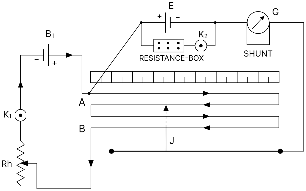
The cell of emf E whose internal resistance r is to be determined is connected in the secondary circuit through a galvanometer, and a resistance box R with a key K2 is connected across this cell, the primary circuit containing B1, Rh and K1.
Open circuit : With K2 open, no current is drawn from the cell, so the balance point corresponds to its emf E. Let this balancing length be l1. Then
Cell sending current through R : A resistance R is now introduced and K2 is closed. The cell sends a current through R, so the balance point now corresponds to its terminal potential difference V. Let this balancing length be l2. Then
Dividing,
Since V = IR and E = I(R + r),
Therefore,
Read the passage(s) and answer the following questions :
The potentiometer is a device used to measure potential difference accurately. If we use a voltmeter to measure potential difference there will be atleast one per cent error. The principle of working of potentiometer lies in the balancing of one voltage against another in parallel with it.
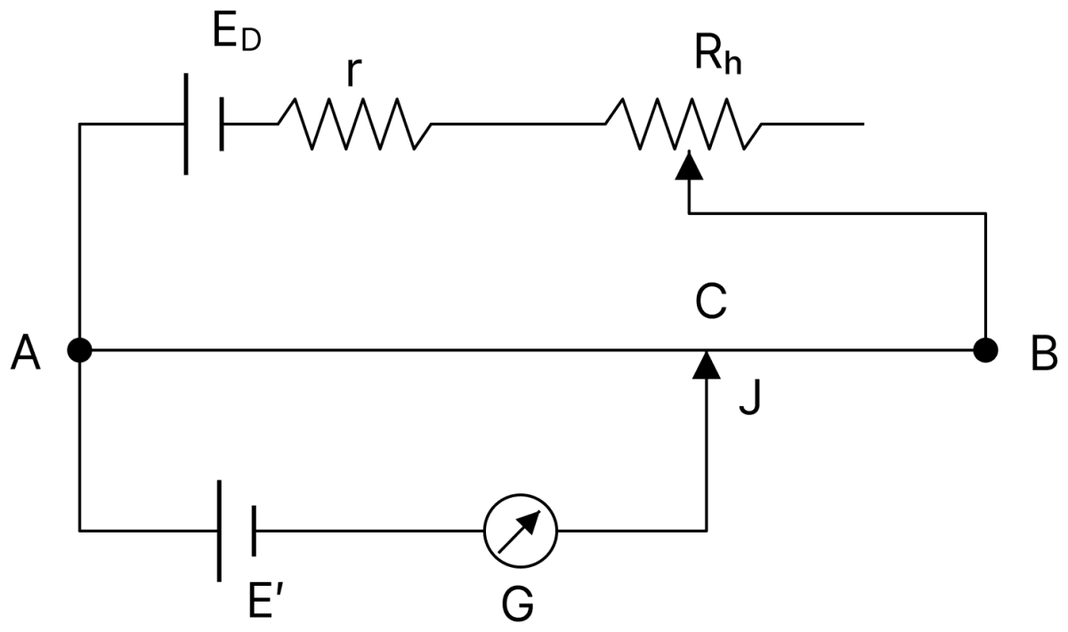
(i) State working principle of potentiometer.
(ii) How can we increase the sensitivity of a potentiometer?
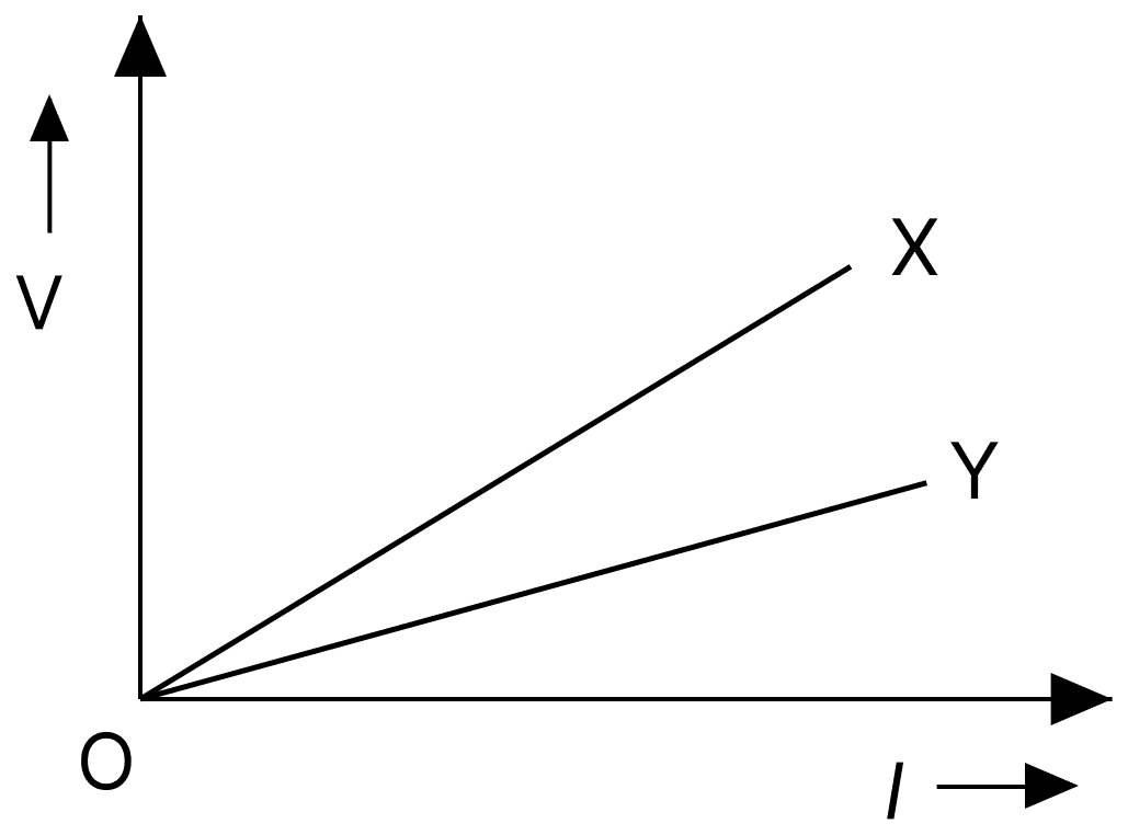
(iii) The figure shows the variation of potential difference V with length l of the wire for two potentiometers X and Y. Which one will you prefer to use and why?
(iv) A current of 1.0 mA is flowing through a potentiometer wire of length 4 m and of resistance 4 Ω/m. Calculate the potential gradient of the potentiometer wire. (Internal resistance of the driving cell is negligible).
(v) With a certain cell, the balance point (null point) is obtained at 70 cm from the end of a potentiometer wire. With another cell whose emf differs from that of the first by 0.2 V, the balance point is obtained at 60 cm. Find emf of each cell.
Answer
(i) Working principle : When a steady current flows through a wire of uniform area of cross-section, a constant potential gradient K is set up along its length. If a cell of emf E connected in the secondary circuit is balanced against a length l of the wire, then
Thus the emf of the cell is directly proportional to the balancing length. At the balance point no current is drawn from the cell.
(ii) The sensitivity of a potentiometer is increased by decreasing its potential gradient, since K = IR/L, where I is the current in the wire, R its resistance and L its length. This is done either by increasing the length of the potentiometer wire, or by decreasing the current in the wire with the help of a rheostat in the primary circuit.
(iii) The potentiometer Y is preferred. The slope of the V–l graph gives the potential gradient. The graph Y has the smaller slope, so its potential gradient is smaller. A smaller potential gradient gives a longer balancing length for the same emf, which makes the measurement more sensitive and hence more accurate.
(iv)
Given,
- Current in the wire, I = 1.0 mA = 1.0 × 10⁻³ A
- Length of the wire, L = 4 m
- Resistance per unit length = 4 Ω/m
The resistance of the whole wire is
The potential difference across the whole wire is
The potential gradient is
Hence, the potential gradient of the potentiometer wire is 4 × 10⁻³ V m-1.
(v)
Given,
- Balancing length for the first cell, l1 = 70 cm
- Balancing length for the second cell, l2 = 60 cm
- E1 − E2 = 0.2 V
Since the emf is proportional to the balancing length,
Substituting E2 = E1 − 0.2,
Hence, the emfs of the two cells are 1.4 V and 1.2 V.