
When 5 V potential difference is applied across a wire of length 0.1 m, the drift speed of electrons is 2.5 × 10⁻⁴ m s-1. If the electron density in the wire is 8 × 1028 m-3, the resistivity of the material is close to :
- 1.6 × 10⁻⁸ Ω m
- 1.6 × 10⁻⁷ Ω m
- 1.6 × 10⁻⁶ Ω m
- 1.6 × 10⁻⁵ Ω m
Answer
1.6 × 10⁻⁵ Ω m
Reason —
Given, V = 5 V, l = 0.1 m, vd = 2.5 × 10⁻⁴ m s-1 and n = 8 × 1028 m-3.
The electric field in the wire is
The current density is
By Ohm's law in vector form, , so
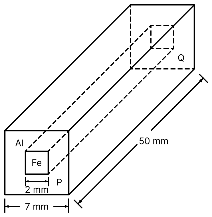
In an aluminium (Al) bar of square cross-section, a square hole is drilled and is filled with iron (Fe) as shown in the figure. The electrical resistivities of Al and Fe are 2.7 × 10⁻⁸ Ω m and 1.0 × 10⁻⁷ Ω m, respectively. The electrical resistance between the two faces P and Q of the composite bar is :
Answer
Reason —
Given, side of the Al bar = 7 mm, side of the Fe core = 2 mm, length l = 50 mm = 0.05 m, ρAl = 2.7 × 10⁻⁸ Ω m and ρFe = 1.0 × 10⁻⁷ Ω m.
Areas of cross-section :
Resistances of the two parts :
The two parts carry the current side by side between the faces P and Q, so they are in parallel,
Across a metallic conductor of non-uniform cross-section a constant potential difference is applied. The quantity which remains constant along the conductor is :
- current
- drift velocity
- electric field
- current density
Answer
current
Reason — For a steady current the same charge crosses every cross-section of the conductor in a given time, so the current I is the same at every section. The current density , the drift velocity and the electric field all depend on the area of cross-section, which is not uniform. Hence only the current remains constant.
A filament bulb (500 W, 100 V) is to be used in a 230 V main supply. When a resistance R is connected in series, it works perfectly and the bulb consumes 500 W. The value of R is :
- 13 Ω
- 230 Ω
- 46 Ω
- 26 Ω
Answer
26 Ω
Reason —
Given, the bulb is rated 500 W, 100 V and the main supply is 230 V.
For the bulb to work perfectly it must consume 500 W at 100 V, so the current through it is
The remaining voltage is dropped across the series resistance R,
The temperature dependence of resistances of Cu and undoped Si in the temperature range 300-400K, is best described by :
- Linear decrease for Cu, linear decrease for Si.
- Linear increase for Cu, linear increase for Si.
- Linear increase for Cu, exponential increase for Si.
- Linear increase for Cu, exponential decrease for Si.
Answer
Linear increase for Cu, exponential decrease for Si.
Reason — Copper is a metal. On heating, the relaxation time τ of its free electrons decreases while the free-electron density n remains practically unchanged, so its resistance increases nearly linearly with temperature.
Undoped silicon is a semiconductor. On heating, the number of free electrons n increases greatly, and this increase far outweighs the decrease in τ. Hence the resistance of silicon decreases exponentially with a rise in temperature.
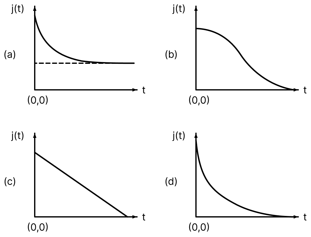
An infinite line charge of uniform electric charge density λ lies along the axis of an electrically conducting infinite cylindrical shell of radius R. At time t = 0, the space inside the cylinder is filled with a material of permittivity ε and electrical conductivity σ. The electrical conduction in the material follows Ohm's law. Which one of the following graphs best describes the subsequent variation of the magnitude of current density j(t) at any point in the material?
Answer
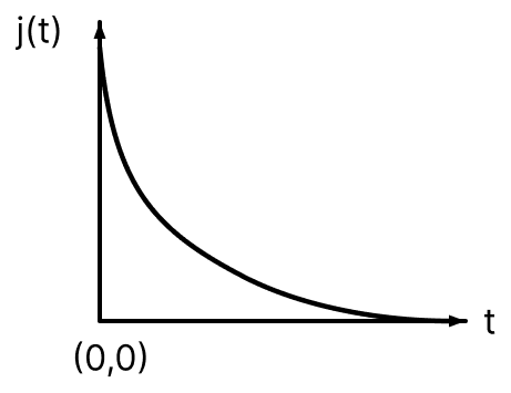
Reason — The line charge produces a radial electric field inside the conducting material, which drives a radial current. This current carries charge away from the axis, so the enclosed charge, and hence the field, goes on decreasing with time.
Let λ be the charge per unit length on the axis at any instant t, and λ0 its value at t = 0. At a point distant r from the axis, the field in the material and, by Ohm's law, the current density are
The current flowing out through a coaxial cylindrical surface of radius r and length l reduces the charge λl enclosed by it,
Separating the variables and integrating from t = 0 to t,
Since j ∝ λ, the magnitude of the current density falls off exponentially from an initial value and tends to zero,
Hence, the graph shown in option (d) is the correct one.
The charge flowing through a resistance R varies with time t as Q = at − bt2, where a and b are positive constants. The total heat produced in R is :
Answer
Reason —
Given, Q = at − bt2.
The current is the rate of flow of charge,
The current becomes zero when
so the charge flows only up to this instant. The total heat produced is
Expanding the square and integrating term by term,
Substituting the limits,
The resistance of a wire is 'R' ohm. If it is melted and stretched to 'n' times its original length, its new resistance will be :
- nR
- n2R
Answer
n2R
Reason — When the wire is melted and stretched, its volume remains constant. If the length becomes n times, the area of cross-section becomes times. Hence
A current of 5 A passes through a copper conductor (resistivity = 1.7 × 10⁻⁸ Ωm) of radius of cross-section 5 mm. Find the mobility of the charges if their drift velocity is 1.1 × 10⁻³ m/s.
- 1.0 m2/Vs
- 1.8 m2/Vs
- 1.5 m2/Vs
- 1.3 m2/Vs
Answer
1.0 m2/Vs
Reason —
Given, I = 5 A, ρ = 1.7 × 10⁻⁸ Ωm, r = 5 mm = 5 × 10⁻³ m and vd = 1.1 × 10⁻³ m/s.
Area of cross-section :
Current density :
Electric field :
Mobility :
Drift speed of electrons, when 1.5 A of current flows in a copper wire of cross-section 5 mm2 is v. If the electron density in copper is 9 × 1028/m3, the value of v in mm/s is close to (Take, charge of electron to be = 1.6 × 10⁻¹⁹ C) :
- 0.02
- 0.2
- 2
- 3
Answer
0.02
Reason —
Given, I = 1.5 A, A = 5 mm2 = 5 × 10⁻⁶ m2, n = 9 × 1028 m-3 and e = 1.6 × 10⁻¹⁹ C.
From I = n e A vd,
Converting to mm/s,
Space between two concentric conducting spheres of radii a and b (b > a) is filled with a medium of resistivity ρ. The resistance between the two spheres will be :
Answer
Reason — Consider a thin spherical shell of the medium of radius x and thickness dx lying between the two spheres. The current flows radially, so for this shell the length is dx and the area of cross-section is 4πx2. Its resistance is
All such shells from x = a to x = b are in series, so the total resistance is
A metal wire of resistance 3 Ω is elongated to make a uniform wire of double its previous length. This new wire is now bent and the ends joined to make a circle. If two points on this circle make an angle 60° at the centre, the equivalent resistance between these two points will be :
Answer
Reason —
Given, the original resistance is 3 Ω and the wire is elongated to double its length.
On elongating, the volume remains constant, so and
This wire is bent into a circle. Two points making an angle 60° at the centre divide the circle into an arc of 60° and an arc of 300°. The resistance of an arc is proportional to the angle it subtends, so
The two arcs are in parallel between the two points,
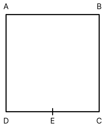
A wire of resistance R is bent to form a square ABCD as shown in the figure. The effective resistance between E and C is : (E is mid-point of arm CD)
- R
Answer
Reason —
Given, a wire of total resistance R is bent to form the square ABCD, and E is the mid-point of the arm CD.
The resistance of each side of the square is , and since E is the mid-point of CD,
Between the points E and C there are two paths in parallel :
(i) the direct path E → C, of resistance
(ii) the path E → D → A → B → C, of resistance
Hence
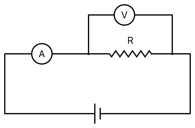
The actual value of resistance R, shown in the figure is 30 Ω. This is measured in an experiment as shown using the standard formula , where V and I are the readings of the voltmeter and ammeter, respectively. If the measured value of R is 5% less, then the internal resistance of the voltmeter is :
- 600 Ω
- 570 Ω
- 350 Ω
- 35 Ω
Answer
570 Ω
Reason —
Given, the actual value of the resistance is R = 30 Ω and the measured value is 5% less.
In the circuit shown the voltmeter is connected across R, so the ammeter measures the current through the parallel combination of R and the voltmeter resistance RV. Hence the measured value is this parallel combination,
In an experiment, the resistance of a material is plotted as a function of temperature (in some range). As shown in the figure, it is a straight line.
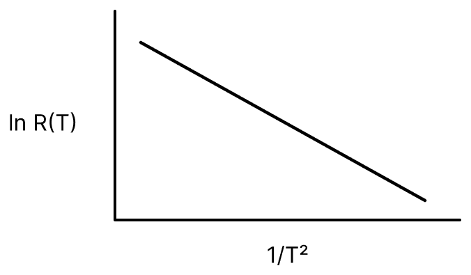
One may conclude that :
Answer
Reason —
From the figure, the graph of ln R(T) against is a straight line with a negative slope, so
where ln R0 is the intercept and the magnitude of the slope. Taking antilogarithms,
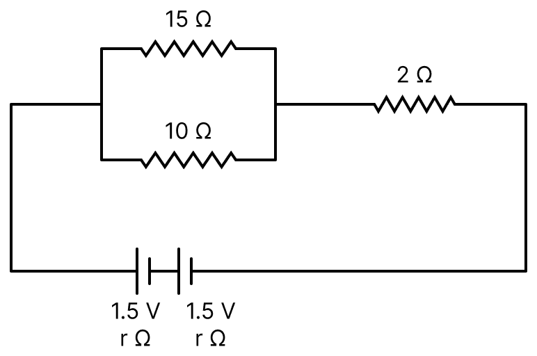
In the given circuit, an ideal voltmeter connected across the 10 Ω resistance reads 2 V. The internal resistance r, of each cell is :
- 1 Ω
- 0.5 Ω
- 1.5 Ω
- 0 Ω
Answer
0.5 Ω
Reason —
Given, two cells each of emf 1.5 V and internal resistance r are joined in series, the 15 Ω and 10 Ω resistances are in parallel, and the 2 Ω is in series with them. The voltmeter reads 2 V across the 10 Ω.
Equivalent resistance of the parallel part :
Current in the circuit : The voltmeter is ideal, so the potential difference across the parallel combination is 2 V. Hence
Applying the circuit equation : The total emf is 1.5 + 1.5 = 3 V and the total resistance is (6 + 2 + 2r) Ω,
A 200 Ω resistor has a certain colour code. If one replaces the red colour by green in the code, the new resistance will be :
- 100 Ω
- 400 Ω
- 500 Ω
- 300 Ω
Answer
500 Ω
Reason — A resistance of 200 Ω is written as 20 × 101 Ω, so its first three colour bands are Red (2), Black (0) and Brown (101).
If the red colour of the first band is replaced by green, the first significant figure becomes 5, and the code now reads Green (5), Black (0) and Brown (101). Hence the new resistance is
A 2 W carbon resistor is colour coded with green, black, red and brown respectively. The maximum current which can be passed through this resistor is :
- 0.4 mA
- 63 mA
- 20 mA
- 100 mA
Answer
20 mA
Reason —
Given, the colour bands are green, black, red and brown, and the power rating of the resistor is 2 W.
Using the colour code, Green corresponds to the figure 5, Black to the figure 0 and Red to the multiplier 102,
The maximum current which can be passed is obtained from P = I2R,
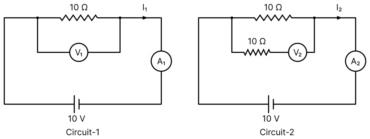
In the given circuits, the readings of voltmeters and the ammeters will be :
- V1 = V2 and I1 = I2
- V2 > V1 and I1 > I2
- V2 > V1 and I1 = I2
- V1 = V2 and I1 > I2
Answer
V1 = V2 and I1 = I2
Reason —
In Circuit-1 the voltmeter V1 is connected across the 10 Ω resistance, and in Circuit-2 the voltmeter V2 is connected in series with an additional 10 Ω and this arrangement is joined across the first 10 Ω.
An ideal voltmeter has infinite resistance, so it draws no current. Hence in Circuit-2 no current flows through the additional 10 Ω and there is no potential drop across it. Both the voltmeters therefore read the potential difference across the 10 Ω resistance of the main circuit, that is,
Since the voltmeters draw no current, the main circuit is the same in both cases and the ammeters also read the same current,
A current of 2 mA was passed through an unknown resistor which dissipated a power of 4.4 W. Dissipated power when an ideal power supply of 11 V is connected across it is :
- 11 × 10-4 W
- 11 × 10-5 W
- 11 × 105 W
- 11 × 10-3 W
Answer
11 × 10-5 W
Reason —
Given, I = 2 mA = 2 × 10⁻³ A and the power dissipated P = 4.4 W.
Resistance of the unknown resistor :
Power dissipated at 11 V :
Two electric bulbs rated at 25 W, 220 V and 100 W, 220 V are connected in series across a 220 V voltage source. If the 25 W and 100 W bulbs draw powers P1 and P2 respectively, then :
- P1 = 16 W, P2 = 4 W
- P1 = 4 W, P2 = 16 W
- P1 = 9 W, P2 = 16 W
- P1 = 16 W, P2 = 9 W
Answer
P1 = 16 W, P2 = 4 W
Reason —
Given, the bulbs are rated 25 W, 220 V and 100 W, 220 V, joined in series across 220 V.
Resistances of the bulbs :
Current in the series circuit :
Powers drawn :
Six similar bulbs are connected as shown in the figure with a DC source of emf E and zero internal resistance.
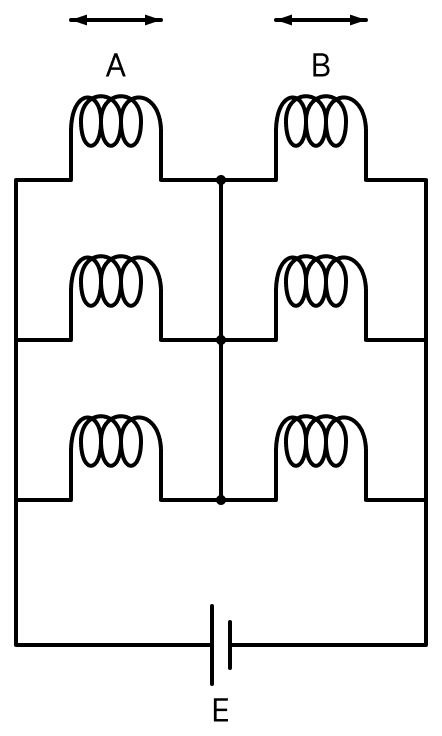
The ratio of power consumption by the bulbs when (i) all are glowing and (ii) in the situation when two from section A and one from section B are glowing, will be :
- 1 : 2
- 2 : 1
- 4 : 9
- 9 : 4
Answer
9 : 4
Reason —
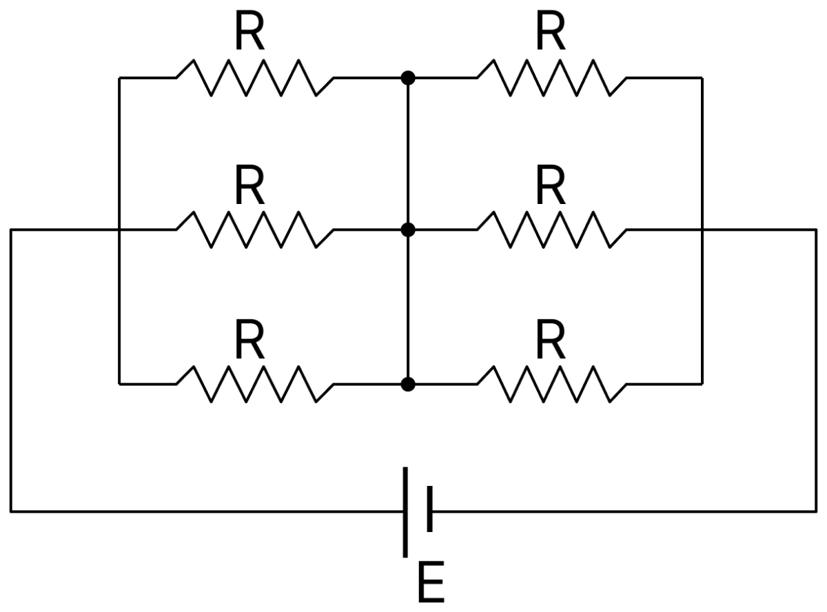
Let the resistance of each bulb be R. Section A has three bulbs in parallel and section B has three bulbs in parallel, and the two sections are joined in series across the source of emf E.
(i) When all the six are glowing :
(ii) When two from A and one from B are glowing :
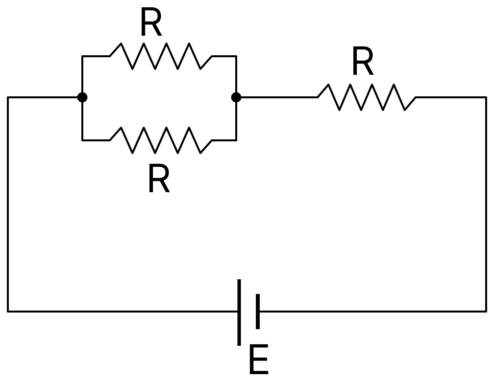
Ratio :
Two solid conductors are made up of same material, have same length and same resistance. One of them has a circular cross section of area A1 and the other one has a square cross section of area A2. The ratio A1/A2 is :
- 2
- 1.5
- 1
- 0.8
Answer
1
Reason — The two conductors are of the same material, so they have the same resistivity ρ, and they have the same length l and the same resistance R. From
Since ρ, l and R are the same for both, their areas of cross-section must also be equal, whatever be the shape of the cross-section. Hence
Consider four conducting materials copper, tungsten, mercury and aluminium with resistivity ρC, ρT, ρM and ρA respectively :
- ρM > ρA > ρC
- ρC > ρA > ρT
- ρA > ρM > ρC
- ρA > ρT > ρC
Answer
ρM > ρA > ρC
Reason — Of the four materials, mercury has by far the largest resistivity (about 98 × 10-8 Ω m), followed by tungsten, aluminium and copper. Among aluminium and copper, copper has the lower resistivity, which is why copper wires are used as connecting wires. Hence the correct order among these three materials is
An electrical power line, having a total resistance of 2 Ω, delivers 1 kW at 220 V. The efficiency of the transmission line is approximately :
- 85%
- 96%
- 72%
- 91%
Answer
96%
Reason —
Given, the power delivered P = 1 kW = 1000 W at V = 220 V, and the total resistance of the line R = 2 Ω.
Current in the line :
Power lost in the line :
Efficiency of transmission :
Two resistors 400 Ω and 800 Ω are connected in series across a 6 V battery. The potential difference measured by a voltmeter of 10 kΩ across 400 Ω resistor is close to:
- 2.05 V
- 1.8 V
- 2 V
- 1.95 V
Answer
1.95 V
Reason —
Given, R1 = 400 Ω and R2 = 800 Ω in series across a 6 V battery, and a voltmeter of resistance RV = 10 kΩ = 10000 Ω is connected across the 400 Ω.
Resistance of the 400 Ω with the voltmeter across it :
Current drawn from the battery :
Potential difference measured :
A circuit to verify Ohm's law uses ammeter and voltmeter in series or parallel connected correctly to the resistor. In the circuit :
- Ammeter is always connected in series and voltmeter in parallel
- Both ammeter and voltmeter must be connected in parallel
- Ammeter is always used in parallel and voltmeter is series
- Both ammeter and voltmeter must be connected in series
Answer
Ammeter is always connected in series and voltmeter in parallel
Reason — An ammeter measures the current through the resistor, so the whole current must pass through it and it has to be joined in series. It is given a very low resistance so that it does not appreciably alter the current in the circuit.
A voltmeter measures the potential difference across the resistor, so it has to be joined in parallel with it. It is given a very high resistance so that it draws practically no current from the circuit.
A battery of 3.0 V is connected to a resistor dissipating 0.5 W of power. If the terminal voltage of the battery is 2.5 V, the power dissipated within the internal resistance is :
- 0.10 W
- 0.072 W
- 0.50 W
- 0.125 W
Answer
0.10 W
Reason —
Given, emf of the battery E = 3.0 V, power dissipated in the external resistor P = 0.5 W and terminal voltage V = 2.5 V.
Current in the circuit : The power dissipated in the resistor is P = VI,
Potential drop across the internal resistance :
Power dissipated within the internal resistance :
Column-I gives certain physical terms associated with flow of current through a metallic conductor.
Column-II gives some mathematical relations involving electrical quantities. Match Column-I and Column-II with appropriate relations.
| Column-I | Column-II |
|---|---|
| (A) Drift Velocity | (P) |
| (B) Electrical Resistivity | (Q) nevd |
| (C) Relaxation Period | (R) |
| (D) Current Density | (S) |
- (A) - (R), (B) - (Q), (C) - (S), (D) - (P)
- (A) - (R), (B) - (S), (C) - (P), (D) - (Q)
- (A) - (R), (B) - (S), (C) - (Q), (D) - (P)
- (A) - (R), (B) - (P), (C) - (S), (D) - (Q)
Answer
(A) - (R), (B) - (S), (C) - (P), (D) - (Q)
Reason — Taking the terms of Column-I one by one :
(A) Drift Velocity : The drift velocity acquired by a free electron in a field E is , which is (R).
(B) Electrical Resistivity : From Ohm's law in vector form, , so , which is (S).
(C) Relaxation Period : Since , the relaxation time is , which is (P).
(D) Current Density : The current density is , which is (Q).
The effective resistance of a parallel connection that consists of four wires of equal length, equal area of cross-section and same material is 0.25 Ω. What will be the effective resistance if they are connected in series?
- 4 Ω
- 0.25 Ω
- 0.5 Ω
- 1 Ω
Answer
4 Ω
Reason — Let the resistance of each wire be R'. The four wires are of equal length, equal area of cross-section and the same material, so they are of equal resistance.
In parallel :
In series :
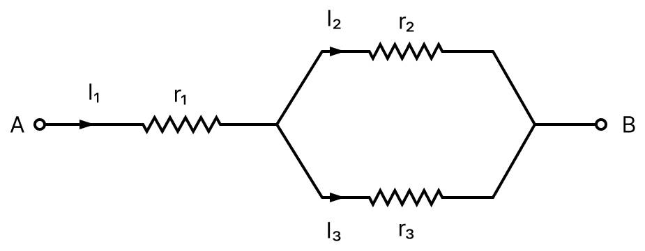
Three resistors having resistances r1, r2 and r3 are connected as shown in the given circuit. The ratio of currents in terms of resistances used in the circuit is :
Answer
Reason —
From the figure, the current I1 enters at A through r1 and then divides into I2 through r2 and I3 through r3, since r2 and r3 are in parallel. Hence
The potential difference across the parallel combination is the same for both branches,
Substituting in the first equation,
What equal length of an iron wire and a copper-nickel alloy wire, each of 2 mm diameter connected parallel to give an equivalent resistance of 3 Ω? (Given : resistivities of iron and copper-nickel alloy wire are 12 µΩ cm and 51 µΩ cm respectively)
- 97 m
- 110 m
- 90 m
- 82 m
Answer
97 m
Reason —
Given, the two wires are of equal length l and each of diameter 2 mm, so the radius is 1 mm = 10-3 m. Their resistivities are
Area of cross-section :
Resistances of the two wires :
In parallel, the equivalent resistance is 3 Ω :
Consider a galvanometer shunted with 5 Ω resistance and 2% of current passes through it. What is the resistance of the given galvanometer?
- 245 Ω
- 344 Ω
- 300 Ω
- 226 Ω
Answer
245 Ω
Reason —
Given, the shunt resistance S = 5 Ω and 2% of the total current passes through the galvanometer.
Let the total current be I. Then the current through the galvanometer is 0.02 I and that through the shunt is 0.98 I.
The galvanometer and the shunt are in parallel, so the potential difference across them is the same,
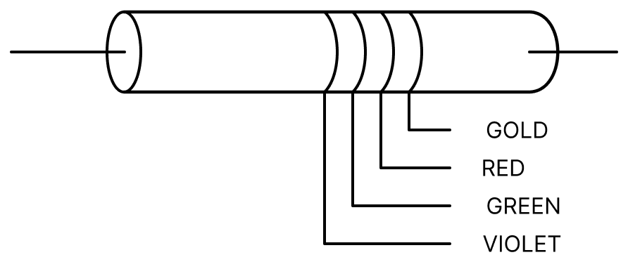
The colour coding on a carbon resistor is shown in the given figure. The resistance value of the given resistor is :
- (7500 ± 375) Ω
- (5700 ± 285) Ω
- (7500 ± 755) Ω
- (5700 ± 375) Ω
Answer
(7500 ± 375) Ω
Reason —
From the figure the colour bands in order are Violet, Green, Red and Gold.
Using the colour code, Violet corresponds to the figure 7, Green to the figure 5, Red to the multiplier 102, and Gold to a tolerance of 5%. Hence
Hence the resistance is (7500 ± 375) Ω.
If you are provided a set of resistances 2 Ω, 4Ω, 6Ω and 8 Ω, connect these resistances so as to obtain an equivalent resistance of .
- 2Ω and 6Ω are in parallel with 4Ω and 8Ω in series.
- 4Ω and 6Ω are in parallel with 2Ω and 8Ω in series.
- 2Ω are 4Ω are in parallel with 6Ω and 8Ω in series.
- 6Ω and 8Ω are in parallel with 2Ω and 4Ω in series.
Answer
2Ω are 4Ω are in parallel with 6Ω and 8Ω in series.
Reason — Taking the 2 Ω and the 4 Ω in parallel,
Joining the 6 Ω and the 8 Ω in series with this combination,
which is the required equivalent resistance.
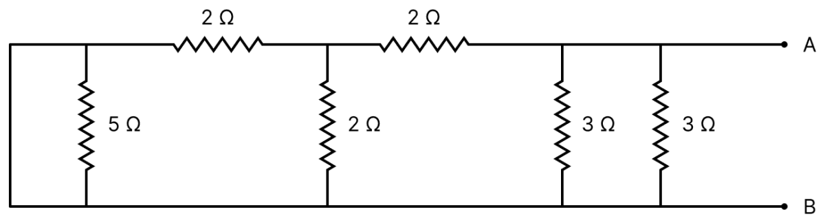
The equivalent resistance of the given circuit between the terminals A and B is :
- 0Ω
- 3Ω
- 1Ω
Answer
1Ω
Reason —
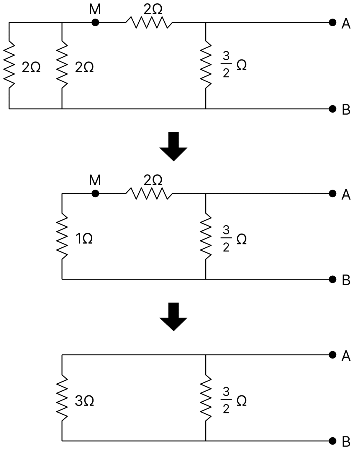
Given,
- Upper wire, from the left-hand corner towards A : 2 Ω up to the middle junction M, then 2 Ω from M
- Vertical arms between the upper and the lower wires, from left to right : 5 Ω, 2 Ω (at M), 3 Ω and 3 Ω
- A plain connecting wire joins the upper and the lower wires at the left-hand end, across the 5 Ω
- A is at the right-hand end of the upper wire and B at the right-hand end of the lower wire
The left-hand vertical connecting wire joins the two ends of the 5 Ω resistance, so the 5 Ω is short-circuited and carries no current. Hence the left-hand upper corner is at the same potential as B.
The two 3 Ω arms are joined directly between A and B, so
The 2 Ω vertical arm at the middle junction M and the 2 Ω which reaches B through the left-hand corner are both connected between M and B, that is, they are in parallel,
Adding the 2 Ω between A and M in series,
Finally R3 and R1 are in parallel between A and B,
A current of 5A is passing through a non-linear magnesium wire of cross-section 0.04 m2. At every point the direction of current density is at an angle of 60° with the unitvector area of cross-section. The magnitude of electric field at every point of the conductor is (Resistivity of magnesium ρ = 44 × 10-8 Ωm) :
- 11 × 10-5 V m-1
- 11 × 10-7 Vm-1
- 11 × 10-3 Vm-1
- 11 × 10-2 V m-1
Answer
11 × 10-5 V m-1
Reason —
Given, I = 5 A, A = 0.04 m2, θ = 60° and ρ = 44 × 10-8 Ωm.
The current is the flux of the current density through the area of cross-section,
By Ohm's law in vector form, E = ρ j,
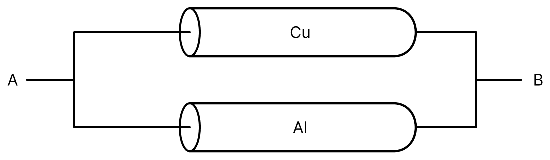
A copper (Cu) rod of length 25 cm and cross-sectional area 3 mm2 is joined with a similar aluminium (Al) rod as shown in figure. Find the resistance of the combination between the ends A and B. (Take resistivity of copper = 1.7 × 10⁻⁸ Ωm, Resistivity of aluminium = 2.6 × 10⁻⁸ Ω m.)
- 2.170 mΩ
- 0.858 mΩ
- 0.0858 mΩ
- 1.420 mΩ
Answer
0.858 mΩ
Reason —
Given, l = 25 cm = 0.25 m, A = 3 mm2 = 3 × 10⁻⁶ m2, ρCu = 1.7 × 10⁻⁸ Ωm and ρAl = 2.6 × 10⁻⁸ Ω m.
Resistance of the copper rod :
Resistance of the aluminium rod :
From the figure the two rods are joined in parallel between A and B,
In the given figure, a battery of emf E is connected across a conductor PQ of length l and different area of cross-section having radii r1 and r2 (r2 < r1).
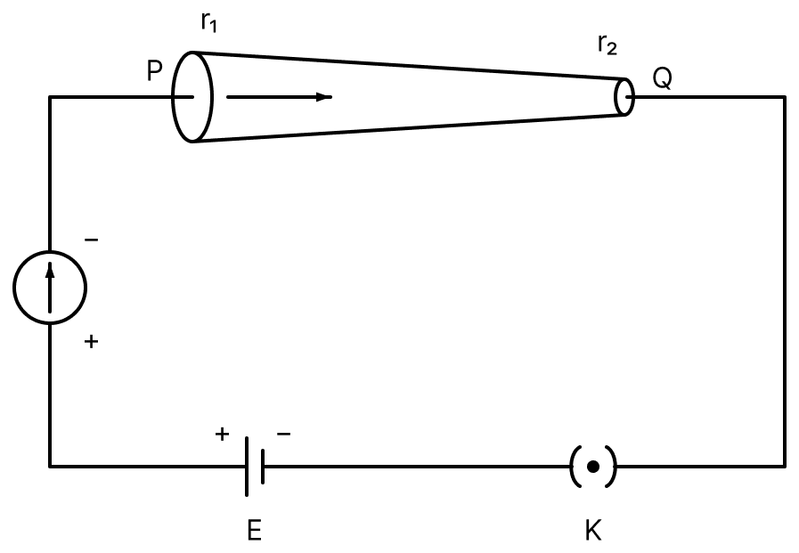
Choose the correct option as one moves from P to Q.
- Electric field decreases.
- Drift velocity of electron increases.
- Electric current decreases.
- All of the above.
Answer
Drift velocity of electron increases.
Reason —
For a steady current the same current I flows through every cross-section of the conductor PQ, so the current does not decrease. Since r2 < r1, the area of cross-section goes on decreasing as one moves from P to Q.
The drift velocity is
so , and the drift velocity increases from P to Q.
The electric field is E = ρ j, and the current density also increases, so the electric field increases as well. Hence only the second statement is correct.
The resistance of a conductor at 15°C is 16Ω and at 100°C is 20Ω. What will be the temperature coefficient of resistance of the conductor?
- 0.042°C-1
- 0.003°C-1
- 0.033°C-1
- 0.010°C-1
Answer
0.003°C-1
Reason —
Given, R1 = 16 Ω at t1 = 15°C and R2 = 20 Ω at t2 = 100°C.
Using Rt = R0(1 + αt) for the two temperatures,
Eliminating R0,
Substituting the values,
A wire of 1 Ω has a length of 1 m. It is stretched till its length increases by 25%. The percentage change in resistance to the nearest integer is :
- 56%
- 76%
- 12.5%
- 25%
Answer
56%
Reason — On stretching, the volume of the wire remains constant, so
The length increases by 25%, so l' = 1.25 l. Hence
To the nearest integer, the percentage change in resistance is 56%.
A conducting wire of length 'l', area of cross-section A and electric resistivity ρ is connected between the terminals of a battery. A potential difference V is developed between its ends, causing an electric current. If the length of the wire of the same material is doubled and the area of cross-section is halved, the resultant current would be :
Answer
Reason — The resistance of the wire is , so the current is
When the length is doubled and the area of cross-section is halved,
Hence the resultant current is
A current through a wire depends on time as i = α0t + βt2t where α0 = 20As-1 and β = 8As-2. Find the charge crossed through a section of the wire in 15s.
- 2250 C
- 11250 C
- 21000 C
- 260 C
Answer
11250 C
Reason —
Given, i = α0t + βt2 with α0 = 20 As-1 and β = 8 As-2, and t = 15 s.
The current is the rate of flow of charge, so
Note: The current in the question is printed as i = α0t + βt2t. The exponent 2t is a misprint; the units given for β (As-2) show that the term must be βt2, and only then does the integration give the answer in the options.
A current of 10 A exists in a wire of cross sectional area of 5 mm2 with a drift velocity of 2 × 10⁻³ ms-1. The number of free electrons in each cubic metre of the wire is ............... .
- 2 × 10⁶
- 625 × 1025
- 2 × 1025
- 1 × 10²³
Answer
625 × 1025
Reason —
Given, I = 10 A, A = 5 mm2 = 5 × 10⁻⁶ m2, vd = 2 × 10⁻³ ms-1 and e = 1.6 × 10⁻¹⁹ C.
From I = n e A vd,
(A) The drift velocity of electrons decreases with the increase in the temperature of conductor.
(B) The drift velocity is inversely proportional to the area of cross-section of given conductor.
(C) The drift velocity does not depend on the applied potential difference to the conductor.
(D) The drift velocity of electron is inversely proportional to the length of the conductor.
(E) The drift velocity increases with the increase in the temperature of conductor.
Choose the correct answer from the options given below.
- (A) and (B)
- (A) and (D)
- (B) and (E)
- (B) and (C)
Answer
(A) and (D)
Reason — The drift velocity in terms of the potential difference applied across a wire of length l is
(A) is correct : With a rise in temperature the metal ions vibrate more vigorously, so the relaxation time τ decreases and hence the drift velocity decreases.
(D) is correct : From the above relation , so the drift velocity is inversely proportional to the length of the conductor.
(B) is wrong, because the expression contains no area of cross-section. (C) is wrong, because vd is directly proportional to V. (E) is wrong, being the opposite of (A).
Two metallic wires of identical dimensions are connected in series. If σ1 and σ2 are the conductivities of these wires respectively, the effective conductivity of the combination is :
Answer
Reason — Let each wire be of length l and area of cross-section A. Since , the resistances are
In series,
The combination is a single conductor of length 2l and the same area A. If σ is its effective conductivity,
Given below are two statements :
Statement I : A uniform wire of resistance 80Ω is cut into four equal parts. These parts are now connected in parallel. The equivalent resistance of the combination will be 5Ω.
Statement II : Two resistances 2R and 3R are connected in parallel in a electric circuit. The value of thermal energy developed in 3R and 2R will be in the ratio 3 : 2.
In the light of the above statements, choose the most appropriate answer from the option given below :
- Both statement I and statement II are correct.
- Both statement I and statement II are incorrect.
- Statement I is correct but statement II is incorrect.
- Statement I is incorrect but statement II is correct.
Answer
Statement I is correct but statement II is incorrect.
Reason —
Statement I : When a wire of resistance 80 Ω is cut into four equal parts, the resistance of each part is . Joining these four in parallel,
Hence Statement I is correct.
Statement II : In a parallel combination the same potential difference V acts across both the resistances, so the thermal energy developed is
The ratio is 2 : 3 and not 3 : 2, so Statement II is incorrect.
A 1 m long wire is broken into two unequal parts X and Y. The X part of the wire is stretched into another wire W. Length of W is twice the length of X and the resistance of W is twice that of Y. Find the ratio of length of X and Y.
- 1 : 4
- 1 : 2
- 4 : 1
- 2 : 1
Answer
1 : 2
Reason — Let the resistance per unit length of the original wire be k, and let the lengths of the parts X and Y be x and y. Then
The part X is stretched into the wire W whose length is twice that of X. On stretching, the volume remains constant, so and
It is given that RW = 2RY,
Following are two statements : One is labelled as Assertion A and the other is labelled as Reason R.
Assertion A : Alloys such as constantan and manganin are used in making standard resistance coils.
Reason R : Constantan and manganin have very small value of temperature coefficient of resistance.
In the light of the above statements, choose the correct answer from the options given below.
- Both A and R are true and R is the correct explanation of A.
- Both A and R are true but R is NOT the correct explanation of A.
- A is true but R is false.
- A is false but R is true.
Answer
Both A and R are true and R is the correct explanation of A.
Reason —
Assertion A is true: A standard resistance coil must keep its marked value even when it warms up on carrying a current, and alloys such as constantan and manganin are used in making such coils.
Reason R is true: Constantan and manganin have a very small temperature coefficient of resistance, so their resistance is hardly affected by a change of temperature.
The Reason is the very property that makes these alloys suitable for standard resistance coils, so R is the correct explanation of A.
Two identical cells each of emf 1.5 V are connected in parallel across a parallel combination of two resistors each of resistance 20Ω. A voltmeter connected in the circuit measures 1.2 V. The internal resistance of each cell is :
- 2.5Ω
- 4Ω
- 5 Ω
- 10Ω
Answer
5 Ω
Reason —
Given, two identical cells each of emf 1.5 V and internal resistance r joined in parallel, and two resistors of 20 Ω each joined in parallel. The voltmeter reads V = 1.2 V.
External resistance :
Equivalent emf and internal resistance : For two identical cells in parallel the emf remains 1.5 V and the internal resistance becomes .
Terminal voltage :
What will be the most suitable combination of three resistors A = 2Ω, B = 4 Ω, C = 6Ω, so that is equivalent resistance of combination?
- Parallel combination of A and C connected in series with B.
- Parallel combination of A and B connected in series with C.
- Series combination of A and C connected in parallel with B.
- Series combination of B and C connected in parallel with A.
Answer
Parallel combination of A and B connected in series with C.
Reason — Joining A = 2 Ω and B = 4 Ω in parallel,
Joining C = 6 Ω in series with this combination,
which is the required equivalent resistance.
An aluminium wire is stretched to make its length, 0.4% larger. The percentage change in resistance is :
- 0.4%
- 0.2%
- 0.8%
- 0.6%
Answer
0.8%
Reason — On stretching, the volume of the wire remains constant, so
Taking the fractional change,
Two resistors of resistance, 100 Ω and 200Ω are connected in parallel in an electrical circuit. The ratio of the thermal energy developed in 100 Ω to that in 200 Ω in a given time is :
- 4 : 1
- 1 : 2
- 2 : 1
- 1 : 4
Answer
2 : 1
Reason — In a parallel combination the same potential difference V acts across both the resistors, so the thermal energy developed in a given time is
A uniform metallic wire carries a current 2 A, when 3.4 V battery is connected across it. The mass of uniform metallic wire is 8.92 × 10⁻³ kg, density is 8.92 × 10³ kg/m3 and resistivity is 1.7 × 10⁻⁸ Ω m. The length of wire is :
- l = 10 m
- l = 100 m
- l = 5 m
- l = 6.8 m
Answer
l = 10 m
Reason —
Given, I = 2 A, V = 3.4 V, mass m = 8.92 × 10⁻³ kg, density d = 8.92 × 10³ kg/m3 and ρ = 1.7 × 10⁻⁸ Ω m.
Resistance of the wire :
Volume of the wire :
Length of the wire : Since ,
The charge flowing in a conductor changes with time as Q(t) = αt − βt2 + γt3, where α, β and γ are constants. Minimum value of current is
Answer
Reason —
Given, Q(t) = αt − βt2 + γt3.
The current is the rate of flow of charge,
For the current to be minimum,
Substituting this value of t in the expression for i,
The equivalent resistance between A and B is ............... .
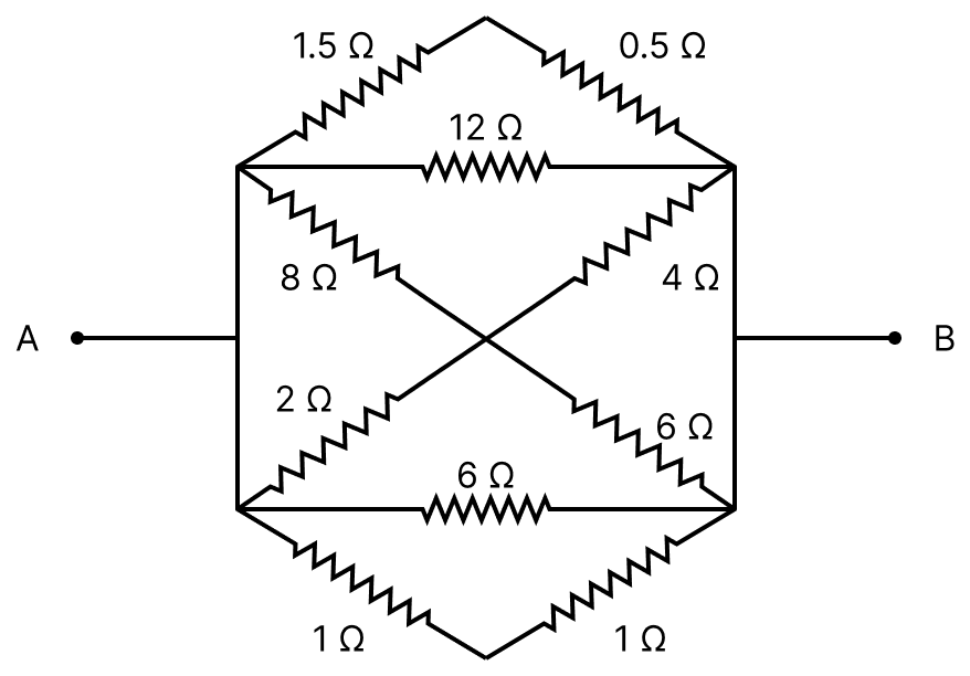
Answer
Reason —
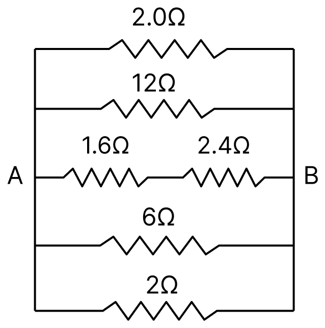
Each of the five branches below is joined between the left-hand vertical wire, which is connected to A, and the right-hand vertical wire, which is connected to B.
Upper arm (1.5 Ω and 0.5 Ω in series) :
Upper horizontal arm : The 12 Ω resistance is joined directly across the network,
Diagonal arms : The two diagonals cross at a common junction O. Between the left side and O, the 8 Ω and 2 Ω are in parallel; between O and the right side, the 4 Ω and 6 Ω are in parallel.
These two parts are in series through O, so
Lower horizontal arm : The 6 Ω resistance is joined directly across the network,
Lower arm (1 Ω and 1 Ω in series) :
Equivalent resistance : All the five branches are in parallel between A and B, so
The magnitude and direction of the current in the following circuit is :
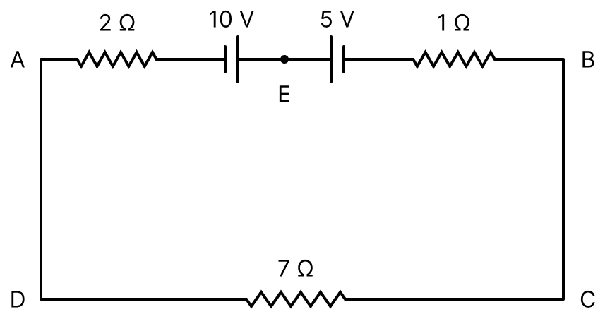
- A from A to B through E
- 1.5 A from B to A through E
- 0.2 A from B to A through E
- 0.5 A from A to B through E
Answer
0.5 A from A to B through E
Reason —
Given, the circuit contains a 10 V and a 5 V source together with resistances of 2 Ω, 1 Ω and 7 Ω.
From the figure the two sources are connected so as to oppose each other, so the net emf driving the current round the loop is
All the three resistances lie in the single loop, so they are in series,
Hence the current is
The 10 V source is the stronger one, so it drives the current in its own sense, that is, from A to B through E.
The resistance of platinum wire at 0°C is 2 Ω and 6.8 Ω at 80°C. The temperature coefficient of resistance of the wire is :
- 3 × 10⁻² °C-1
- 3 × 10⁻¹ °C-1
- 3 × 10⁻⁴ °C-1
- 3 × 10⁻³ °C-1
Answer
3 × 10⁻² °C-1
Reason —
Given, R0 = 2 Ω at 0°C and Rt = 6.8 Ω at t = 80°C.
Using Rt = R0(1 + αt),
An electric toaster has resistance of 60 Ω at room temperature (27°C). The toaster is connected to a 220 V supply. If the current flowing through it reaches 2.75 A, the temperature attained by toaster is around : (if α = 2 × 10⁻⁴/°C)
- 694°C
- 1235°C
- 1694°C
- 1667°C
Answer
1694°C
Reason —
Given, R at 27°C is 60 Ω, V = 220 V, I = 2.75 A and α = 2 × 10⁻⁴/°C.
Resistance of the toaster at the higher temperature :
Rise in temperature : Using R' = R(1 + αΔt),
Temperature attained :
Two conductors have the same resistances at 0°C but their temperature coefficients of resistance are α1 and α2. The respective temperature coefficients for their series and parallel combinations are :
Answer
Reason — Let each conductor have a resistance R at 0°C.
In series :
Since the resistance at 0°C is 2R, the temperature coefficient of the series combination is .
In parallel : The resistance at 0°C is , and at t°C
Since α1t and α2t are very small, the terms containing their product may be neglected,
Hence the temperature coefficient of the parallel combination is also .
A wire of length 'l' and resistance 100 Ω is divided into 10 equal parts. The first 5 parts are connected in series while the next 5 parts are connected in parallel. The two combinations are again connected in series. The resistance of this final combination is :
- 26 Ω
- 52 Ω
- 55 Ω
- 60 Ω
Answer
52 Ω
Reason —
Given, a wire of resistance 100 Ω is divided into 10 equal parts.
Resistance of each part :
First 5 parts in series :
Next 5 parts in parallel :
The two combinations joined in series :
Two heaters A and B have power rating of 1 kW and 2 kW, respectively. Those two are first connected in series and then in parallel to a fixed power source. The ratio of power outputs for these two cases is :
- 1 : 1
- 2 : 9
- 1 : 2
- 2 : 3
Answer
2 : 9
Reason —
Given, the power ratings of the heaters are 1 kW and 2 kW at the same supply voltage V.
Resistances of the heaters :
In series :
In parallel :
Ratio of the power outputs :
Four resistances 40 Ω, 60 Ω, 90 Ω and 110 Ω make the arms of a quadrilateral ABCD. Across AC is a battery of emf 40 V and internal resistance negligible. The potential difference across BD in V is ............... .
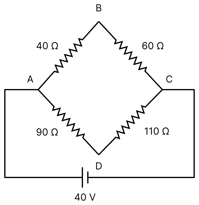
Answer
Given,
- The resistances 40 Ω, 60 Ω, 90 Ω and 110 Ω form the arms AB, BC, AD and DC of the quadrilateral ABCD
- A battery of emf 40 V with negligible internal resistance is joined across AC
The branch ABC and the branch ADC are joined in parallel between A and C, so each of them has the full 40 V across it.
Current in the branch ABC :
Current in the branch ADC :
Potentials of B and D relative to A :
Potential difference across BD :
Hence, the potential difference across BD is 2 volt.
A current of 6 A enters one corner P of an equilateral triangle PQR having three wires of resistance 2Ω each and leaves by the corner R. The current i1 in ampere is ............... .
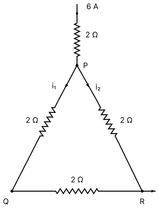
Answer
Given,
- A current of 6 A enters the corner P of the equilateral triangle PQR and leaves by the corner R
- Each side is of resistance 2 Ω
Between P and R there are two paths in parallel :
(i) the direct side PR, of resistance 2 Ω, carrying the current i2
(ii) the path P → Q → R, of resistance 2 + 2 = 4 Ω, carrying the current i1
Since the two branches are in parallel, the potential difference across them is the same,
Also,
Substituting,
Hence, the current i1 is 2 ampere.
A cylindrical wire of radius 0.5 mm and conductivity 5 × 10⁷ S/m is subjected to an electric field of 10 mV/m. The expected value of current in the wire will be x3 π mA. The value of x is ............... .
Answer
Given,
- Radius of the wire, r = 0.5 mm = 0.5 × 10⁻³ m
- Conductivity, σ = 5 × 10⁷ S/m
- Electric field, E = 10 mV/m = 10 × 10-3 V/m
Current density : By Ohm's law in vector form,
Area of cross-section :
Current in the wire :
Comparing with the given form I = x3π mA,
Hence, the value of x is 5.
Two wires of same length and thickness having specific resistances 6Ω-cm and 3Ω-cm respectively are connected in parallel. The effective resistivity is ρΩ-cm. The value of ρ to the nearest integer, is ............... .
Answer
Given,
- The two wires are of the same length l and the same thickness, that is, the same area of cross-section A
- Specific resistances, ρ1 = 6 Ω-cm and ρ2 = 3 Ω-cm
Resistances of the two wires :
Equivalent resistance in parallel :
Effective resistivity : The parallel combination behaves as a single conductor of length l and area of cross-section 2A. If ρ is its effective resistivity, then
Hence, the value of ρ to the nearest integer is 4.
In the given figure, switches S1 and S2 are in open condition. The resistance across ab when the switches S1 and S2 are closed is ............... Ω.
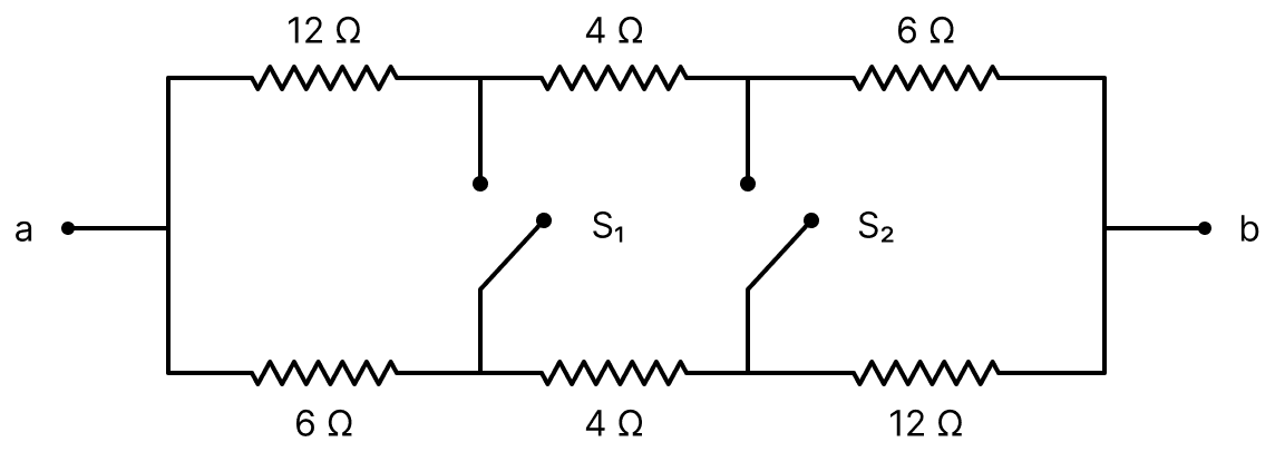
Answer
Given,
- Upper row, from a to b : 12 Ω, 4 Ω and 6 Ω
- Lower row, from a to b : 6 Ω, 4 Ω and 12 Ω
- S1 joins the first pair of inner junctions (after the 12 Ω above and the 6 Ω below), and S2 joins the second pair (after the 4 Ω in each row)
- Both the switches S1 and S2 are closed
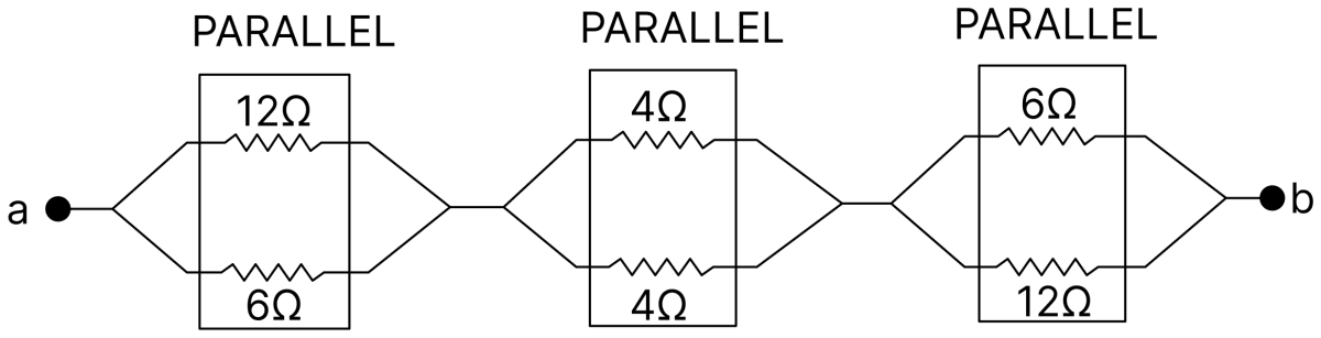
When both the switches are closed, the corresponding junctions of the upper and the lower rows are joined together. Hence the network becomes three parallel pairs joined in series.
First pair (12 Ω and 6 Ω in parallel) :
Second pair (4 Ω and 4 Ω in parallel) :
Third pair (6 Ω and 12 Ω in parallel) :
These three are in series between a and b,
Hence, the resistance across ab is 10 Ω.
First, a set of n equal resistors of 10 Ω each are connected in series to a battery of emf 20 V and internal resistance 10 Ω. A current I is observed to flow. Then, the n resistors are connected in parallel to the same battery. It is observed that the current is increased 20 times, then the value of n is ............... .
Answer
Given,
- n resistors each of 10 Ω
- Emf of the battery, E = 20 V, internal resistance r = 10 Ω
- The current in parallel is 20 times the current in series
In series : The equivalent resistance of the n resistors is 10n Ω, so
In parallel : The equivalent resistance is Ω, so
It is given that I' = 20 I,
Multiplying throughout by n,
Since n cannot be negative, n = 20.
Hence, the value of n is 20.
A potential V0 is applied across a uniform wire of resistance R. The power dissipation is P1. The wire is then cut into two equal halves and a potential of V0 is applied across the length of each half. The total power dissipation across two wires is P2. The ratio P2 : P1 is : 1. The value of x is ............... .
Answer
Given,
- A potential V0 is applied across a wire of resistance R
- The power dissipation is P1
Power in the first case :
When the wire is cut into two equal halves : The resistance of each half is , and a potential V0 is applied across the length of each half. The power dissipated in one half is
The total power dissipated across the two wires is
Ratio of the powers :
It is given that this ratio is , so
Hence, the value of x is 16.
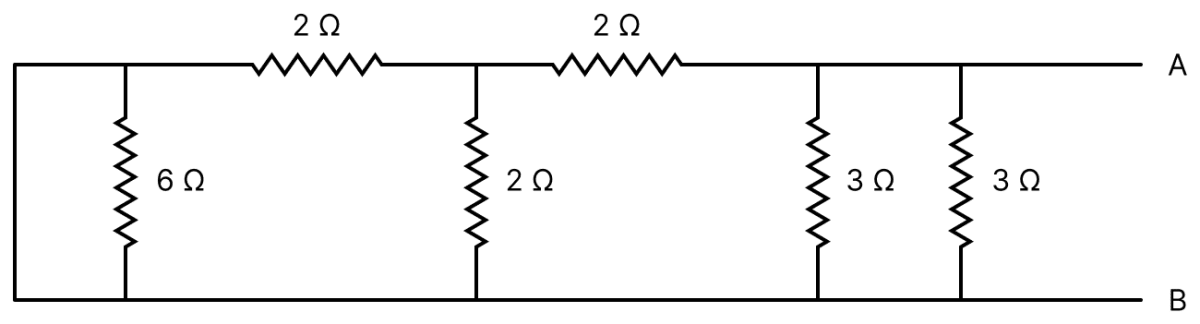
Equivalent resistance of the following network is ............... Ω.
Answer
Given,
- Upper wire, from the left-hand corner towards A : 2 Ω up to the middle junction M, then 2 Ω from M
- Vertical arms between the upper and the lower wires, from left to right : 6 Ω, 2 Ω (at M), 3 Ω and 3 Ω
- A plain connecting wire joins the upper and the lower wires at the left-hand end, across the 6 Ω
- A is at the right-hand end of the upper wire and B at the right-hand end of the lower wire
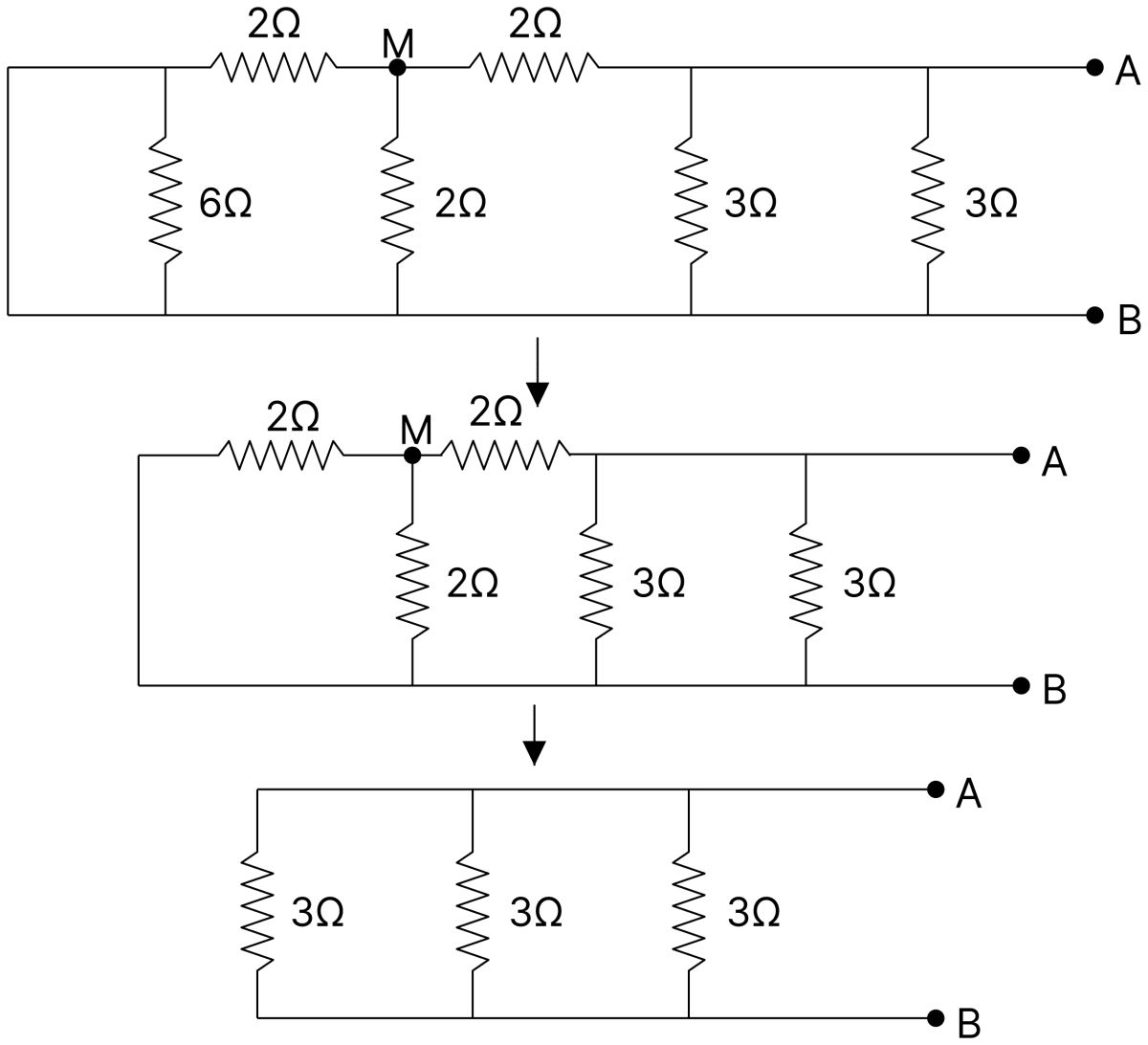
The left-hand vertical connecting wire joins the two ends of the 6 Ω resistance, so the 6 Ω is short-circuited and carries no current. Hence the left-hand upper corner is at the same potential as B.
The 2 Ω vertical arm at the middle junction M and the 2 Ω which reaches B through the left-hand corner are therefore both joined between M and B, that is, they are in parallel,
Adding the 2 Ω between A and M in series,
R2 and the two 3 Ω arms now form three 3 Ω resistances in parallel between A and B, as in the last diagram. Taking the two 3 Ω arms together first,
Finally R2 and R3 are in parallel between A and B,
Hence, the equivalent resistance of the network is 1 Ω.