
Physics
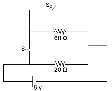
In the below circuit diagram, calculate the power consumed in the circuit when:
(a) the switch S1 is closed, and the switch S2 is open.
(b) the switch S2 is closed, and the switch S1 is open.
Household Circuits
41 Likes
Answer
(a) When switch S1 is closed, and the switch S2 is open.
Here, 60 Ω and 20 Ω are in parallel
Let total resistance of circuit in this condition = R1
So, by formula
Power consumed =
(b) When switch S2 is closed, and the switch S1 is open.
Here, negligible current flows through the 60 Ω resistor because the majority of the current takes the path of least resistance, which includes the 20 Ω resistor. Therefore, most of the current flows through the 20 Ω path.
So, total resistance of circuit R2 = 20 Ω
Power consumed =
Answered By
25 Likes
Related Questions
Two students are conducting experiments with identical 100 g mass simple pendulums, each raising the bob 5 m above the mean position. The graph depicting the relationship between distance from the mean position and velocities is presented in the diagram.

(a) Demonstrate, using mathematical calculations, that the path followed by student 1 is devoid of friction.
(b) Does the situation involving student 2 exhibit a breach of the law of conservation of energy?
Examine the graph depicting the transmitted (T) and reflected (R) waves from submarines A and B, which are equipped with a device emitting ultrasonic sounds. Study the graph and answer the following. (Speed of sound in water is 1500 m/s)
(a) Name the device used here.
(b) Why is ultrasonic sound used in this device?
(c) Which submarine is closer to the ship? Calculate the distance of the closest submarine.

The diagram below shows a pulley used to lift an iron beam of length 3 m and weight 100 kgf, lying on the ground.
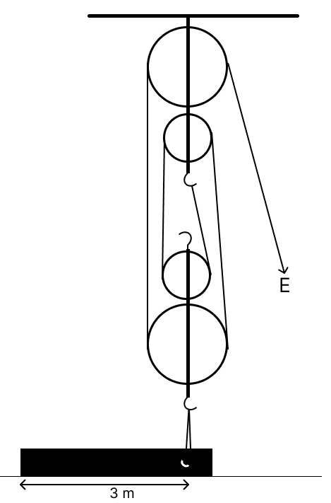
(a) Calculate the minimum effort needed to just lift the beam off the ground. [Assume no loss of energy]
(b) When the beam is being lifted from the ground, with the other end touching the ground, state with a reason whether the effort needed keeps on increasing, decreasing or remains constant.
You are doing an experiment on the refraction of light in your Physics laboratory. ABCD is a rectangular block. A ray of light is incident obliquely on the surface AB.
(a) Draw the path of the ray of light through the glass block and also show how it emerges from the block. [ The diagram should show the lateral displacement suffered by the ray.]
(b) Which two pairs of angles remain the same during the experiment?
(c) If the same experiment is performed first with red and then with blue light, which colour will suffer greater lateral displacement?