
A capacitance of 2 µF is required in an electrical circuit across a potential difference of 1.0 kV. A large number of 1 µF capacitors are available which can withstand a potential difference of not more than 300 V. The minimum number of capacitors required to achieve this is :
- 32
- 2
- 16
- 24
Answer
32
Reason —
Given,
- Required capacitance = 2 µF, across V = 1.0 kV = 1000 V
- Each available capacitor = 1 µF, withstanding at most 300 V
To withstand 1000 V, the capacitors must be joined in series. The number in each row must be
so at least n = 4 capacitors are needed in a row. The capacitance of one row is
If m such rows are joined in parallel to give 2 µF,
Hence the minimum number of capacitors is
The electrostatic force between the metal plates of an isolated parallel plate capacitor C having a charge Q and area A, is :
- independent of the distance between the plates
- inversely proportional to the distance between between the plates
- proportional to the square root of the distance between the plates
- linearly proportional to the distance between the plates
Answer
independent of the distance between the plates
Reason —
Each plate lies in the field produced by the other plate alone, which is
Hence the force on a plate carrying charge Q is
The capacitor is isolated, so Q is fixed. This expression contains no distance term, hence the electrostatic force is independent of the separation between the plates.
A parallel plate capacitor of capacitance 90 pF is connected to a battery of emf 20 V. If a dielectric material of dielectric constant is inserted between the plates, the magnitude of the induced charge will be :
- 2.4 nC
- 0.9 nC
- 1.2 nC
- 0.3 nC
Answer
1.2 nC
Reason —
Given,
- C = 90 pF, V = 20 V, K = 5/3
- The battery remains connected, so V is constant
With the dielectric inserted, the charge on the plates becomes
The charge induced on the faces of the dielectric is
Substituting the values,
A parallel plate capacitor of capacitance 20 µF is being charged by a voltage source whose potential is changing at the rate of 3 V/s. The conduction current through the connecting wires, and the displacement current through the plates of the capacitor, would be, respectively :
- 60 µA, zero
- Zero, zero
- Zero, 60 µA
- 60 µA, 60 µA
Answer
60 µA, 60 µA
Reason —
Given,
- C = 20 µF = 20 × 10-6 F
- V s-1
The charge on the capacitor is q = CV. Differentiating with respect to time,
The displacement current through the gap between the plates is always equal to the conduction current in the wires, so
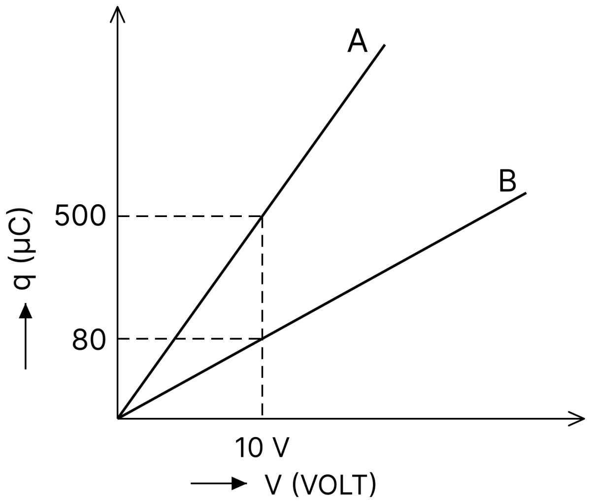
Figure shows charge(q) versus voltage(V) graph for series and parallel combination of two given capacitors. The capacitance are :
- 50 µF and 30 µF
- 40 µF and 10 µF
- 20 µF and 30 µF
- 60 µF and 40 µF
Answer
40 µF and 10 µF
Reason —
From the graph, the slope q/V gives the capacitance. The line A of greater slope is the parallel combination and the line B the series combination,
If the two capacitances are C1 and C2,
so that
Hence C1 and C2 are the roots of
Voltage rating of a parallel plate capacitor is 500 V. Its dielectric can withstand a maximum electric field of 106 V/m. The plate area is 10-4 m2. What is the dielectric constant if the capacitance is 15 pF?
(Given ε0 = 8.86 × 10⁻¹² C2/Nm2)
- 3.8
- 4.5
- 6.2
- 8.5
Answer
8.5
Reason —
Given,
- V = 500 V, Emax = 106 V m-1
- A = 10-4 m2, C = 15 pF = 15 × 10-12 F
The least permissible separation follows from E = V/d,
For a capacitor filled with a dielectric,
Substituting the values,
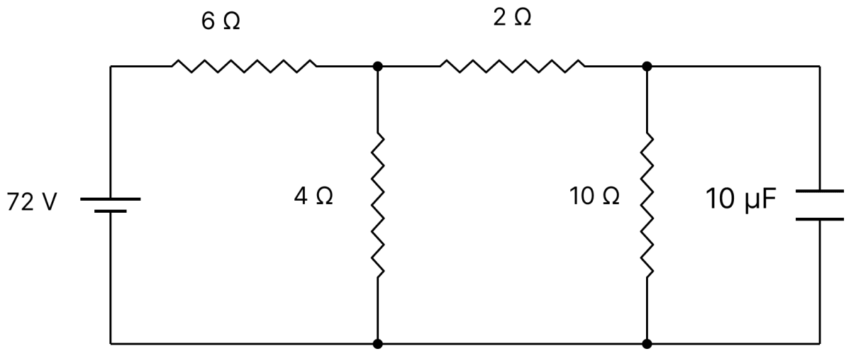
Determine the charge on the capacitor in the following circuit :
- 2 µC
- 60 µC
- 200 µC
- 10 µC
Answer
200 µC
Reason —
Given, emf = 72 V, resistances 6 Ω, 4 Ω, 2 Ω and 10 Ω, and C = 10 µF.
In the steady state no current flows through the branch containing the capacitor, so the capacitor is simply connected across the 10 Ω resistor.
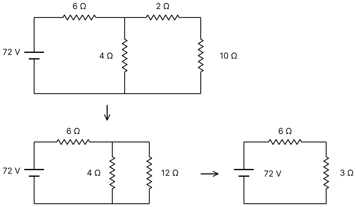
The 4 Ω resistor is in parallel with the series pair (2 Ω + 10 Ω = 12 Ω),
The total resistance of the circuit is
The potential difference across the parallel section is
The current in the 12 Ω branch is
so the potential difference across the 10 Ω resistor, and hence across the capacitor, is
Therefore
A capacitor with capacitance 5 µF is charged to 5 µC. If the plates are pulled apart to reduce the capacitance to 2 µF, how much work is done?
- 3.75 × 10⁻⁶ J
- 2.55 × 10⁻⁶ J
- 2.16 × 10⁻⁶ J
- 6.25 × 10⁻⁶ J
Answer
3.75 × 10⁻⁶ J
Reason —
Given,
- C1 = 5 µF, C2 = 2 µF, charge q = 5 µC = 5 × 10⁻⁶ C
The charge remains constant while the plates are pulled apart, so the work done equals the increase in the stored energy,
Substituting the values,
The parallel combination of two air filled parallel plate capacitors of capacitance C and nC is connected to a battery of voltage, V. When the capacitors are fully charged, the battery is removed and after that a dielectric material of dielectric constant K is placed between the two plates of the first capacitor. The new potential difference of the combined system is :
- V
Answer
Reason —
The two capacitors in parallel have a total capacitance C + nC = (n + 1)C, so the total charge stored is
The battery is then removed, so this charge remains constant. On introducing the dielectric in the first capacitor, its capacitance becomes KC, and the total capacitance is
Hence the new common potential difference is
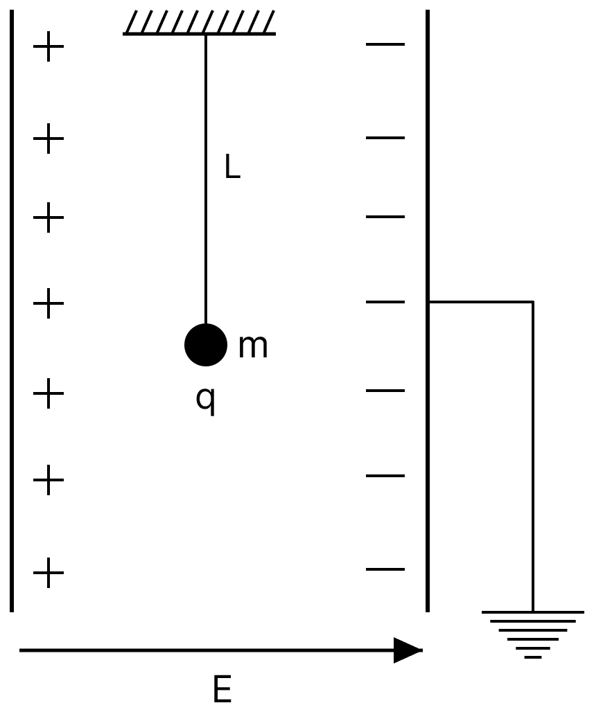
A simple pendulum of length L is placed between the plates of a parallel plate capacitor having electric field E, as shown in figure. Its bob has mass m and charge q. The time-period of the pendulum is given by :
Answer
Reason —
Given,
- Length of the pendulum = L
- Mass of the bob = m, charge on the bob = q
- Electric field between the plates = E, directed horizontally
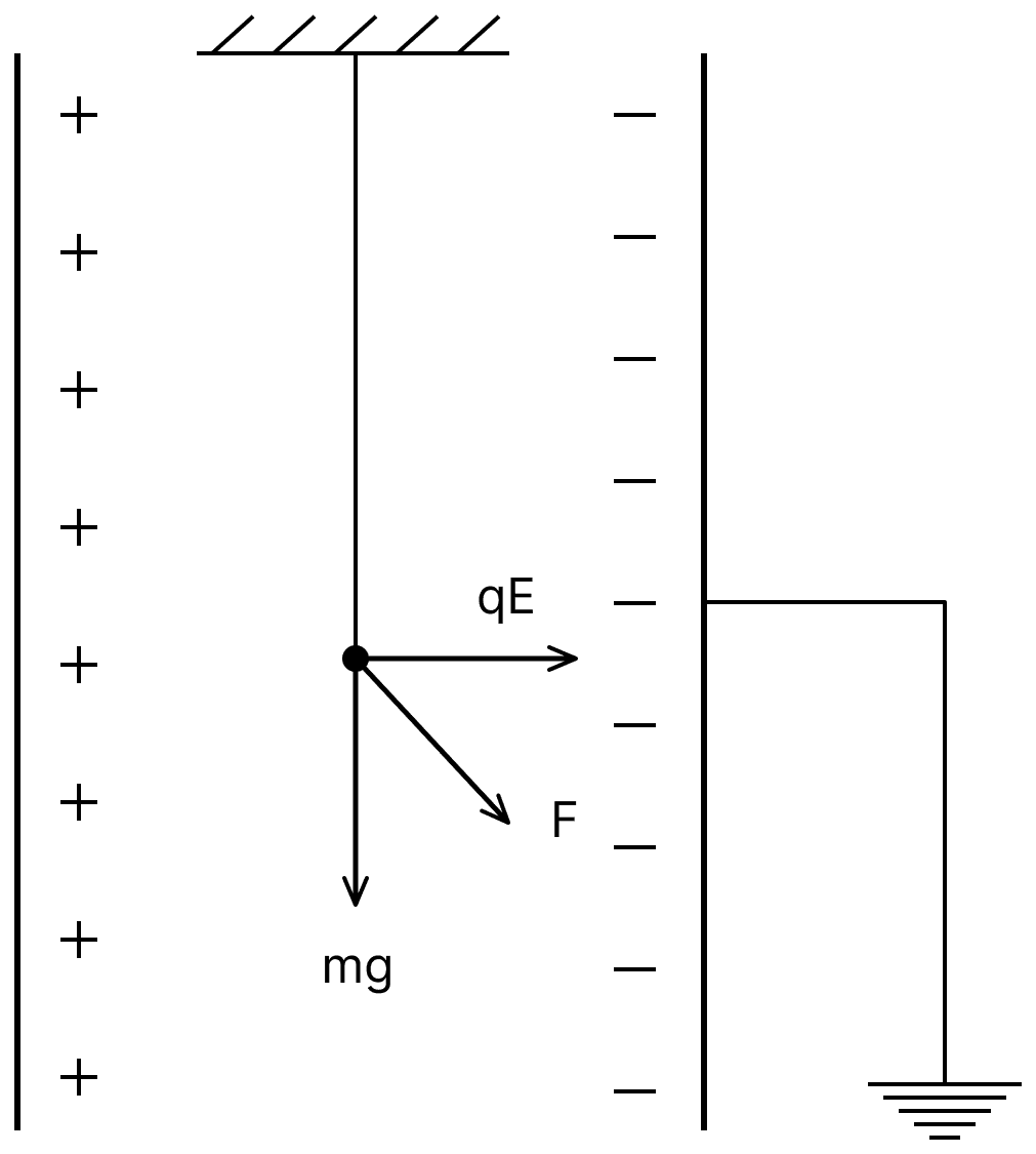
Forces acting on the bob : the plates of the capacitor are vertical, so the field E between them is horizontal. The bob therefore experiences
(i) its weight mg, acting vertically downwards, and
(ii) the electric force qE, acting horizontally, along the direction of the field.
Resultant acceleration : the two forces are mutually perpendicular, so their resultant is obtained by the theorem of parallelogram of vectors,
The effective acceleration of the bob is this resultant force divided by the mass,
Taking m inside the radical,
Time period : the bob now oscillates about the new equilibrium position, which is the line of the resultant force, and the time period of a simple pendulum in an effective gravitational field geff is
Substituting the value of geff,
The options in which g and qE/m are simply added or subtracted would apply only if the electric force were vertical, that is, parallel or antiparallel to gravity. Here the field is horizontal, so the two accelerations must be combined vectorially.
A parallel plate capacitor has 1 µF capacitance. One of its two plates is given +2 µC charge and the other plate, +4 µC charge. The potential difference developed across the capacitor is :
- 5 V
- 2 V
- 3 V
- 1 V
Answer
1 V
Reason —
Given, C = 1 µF, q1 = + 2 µC and q2 = + 4 µC.
When two plates carry unequal charges, only the difference of the charges is responsible for the field between them; half of this difference resides as the effective charge of the capacitor. Hence
Substituting the values,
In the circuit shown, find C if the effective capacitance of the whole circuit is to be 0.5 µF. All values in the circuit are in µF.
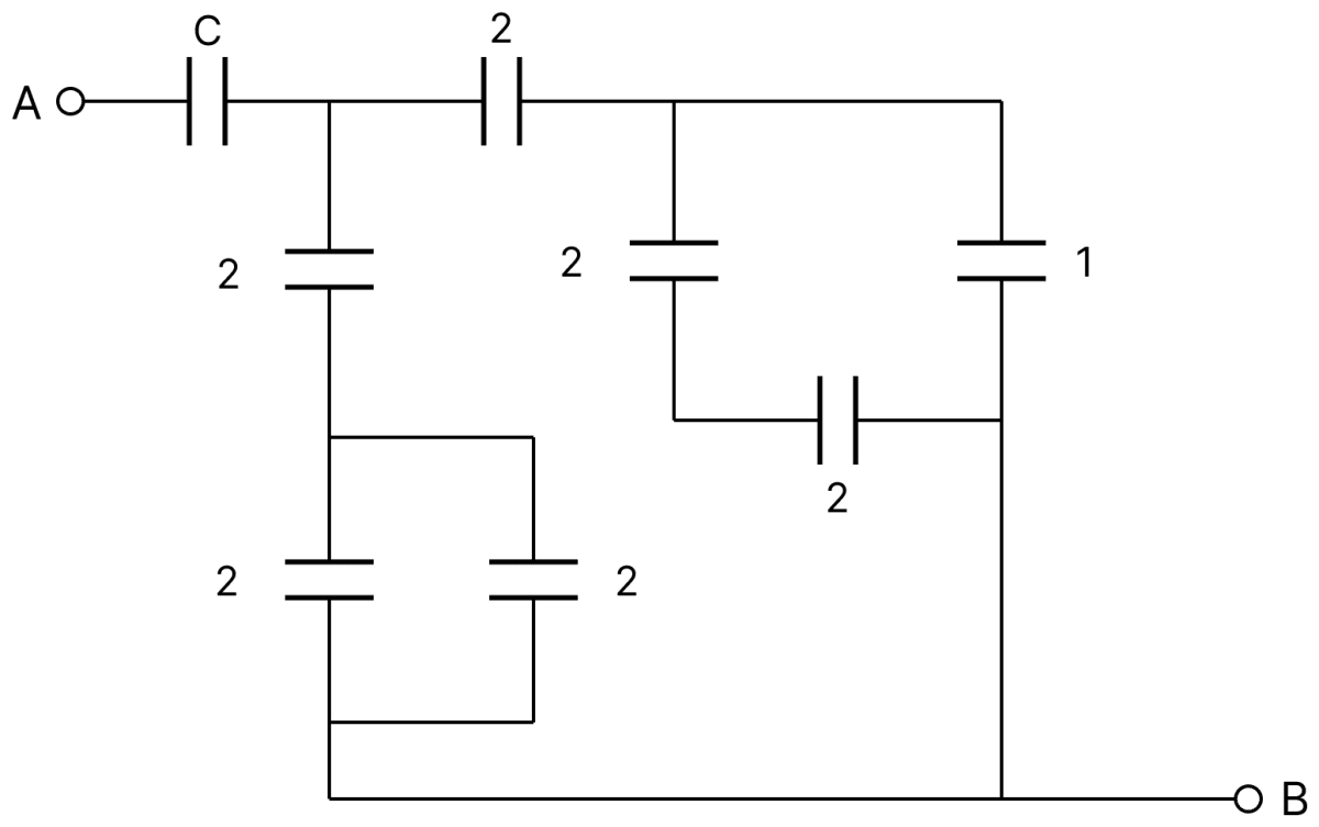
- µF
- 4 µF
- µF
- µF
Answer
µF
Reason —
Let P be the junction just after C, and let the lower rail be B.
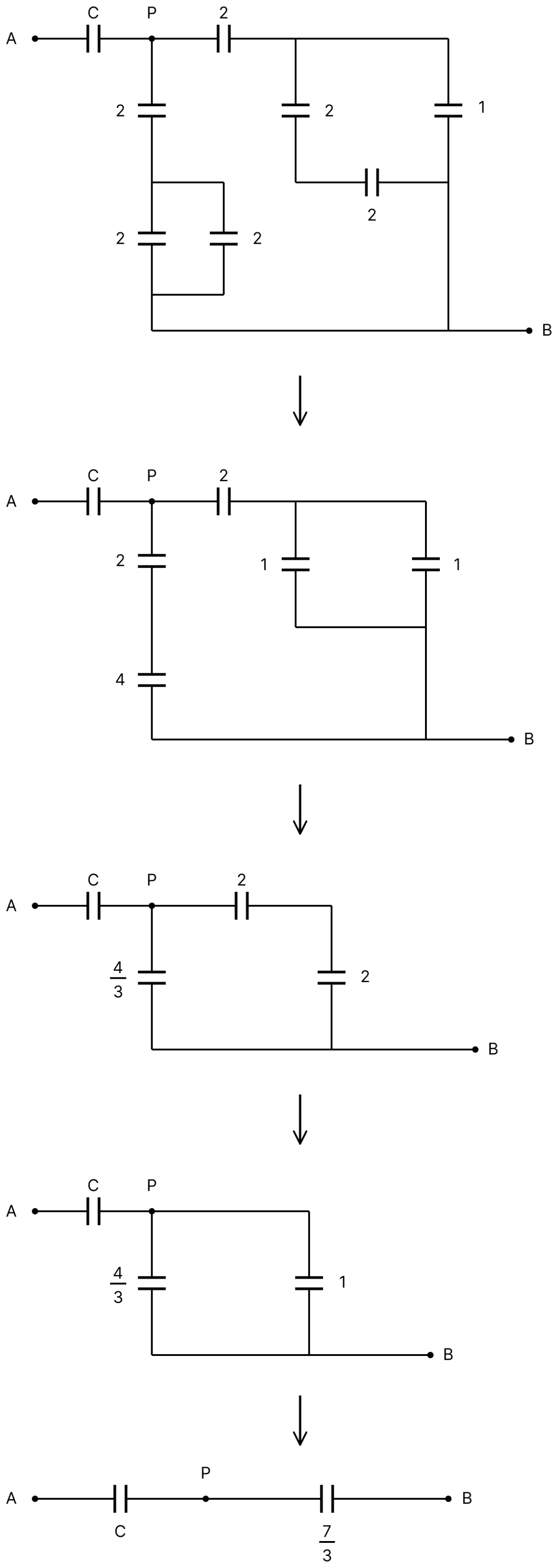
Left branch from P : the 2 µF vertical capacitor is in series with the parallel pair of 2 µF and 2 µF at the bottom,
Right branch from P : the two 2 µF capacitors of the right-hand group are in series, giving 1 µF, and this is in parallel with the 1 µF capacitor, giving 2 µF. This is reached from P through the top 2 µF capacitor,
Between P and B : the two branches are in parallel,
Finally C is in series with this,
The charge on a capacitor plate in a circuit as a function of time is shown in the figure.
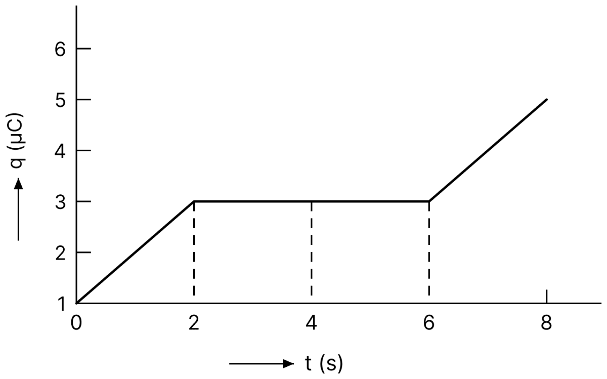
What is the value of current at t = 4 s?
- 2 µA
- 1.5 µA
- Zero
- 3 µA
Answer
Zero
Reason —
The current is the rate of change of charge,
which is given by the slope of the q–t graph. Between t = 2 s and t = 6 s the graph is a horizontal straight line, that is, the charge stays constant at 3 µC. Hence at t = 4 s the slope is zero and so the current is zero.
A parallel plate capacitor having capacitance 12 pF is charged by a battery to a potential difference of 10 V between its plates. The charging battery is now disconnected and a porcelain slab of dielectric constant 6.5 is slipped between the plates. The work done by the capacitor on the slab is :
- 560 pJ
- 508 pJ
- 692 pJ
- 600 pJ
Answer
508 pJ
Reason —
Given, C = 12 pF, V = 10 V and K = 6.5.
The initial energy stored is
The battery is disconnected, so the charge remains constant while the capacitance becomes KC. Hence
The work done by the capacitor in drawing the slab in is the decrease in its stored energy,
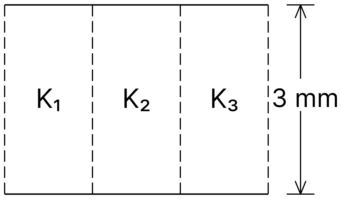
A parallel plate capacitor is of area 6 cm2 and a separation 3 mm. The gap is filled with three dielectric materials of equal thickness (see figure) with dielectric constants K1 = 10, K2 = 12 and K3 = 14. The dielectric constant of a material which give same capacitance when fully inserted in above capacitor, would be :
- 4
- 36
- 12
- 14
Answer
12
Reason —
From the figure the three dielectrics occupy three equal parts of the plate area, each of area A/3, with the full separation d. They therefore behave as three capacitors joined in parallel,
If a single material of dielectric constant K fully filled the capacitor, then C = Kε0A/d. Comparing the two,
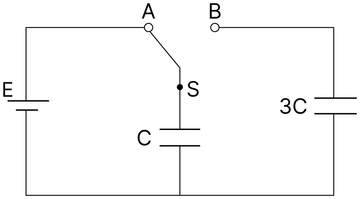
In the figure shown, after the switch 'S' is turned from position 'A' to position 'B', the energy dissipated in the circuit in terms of capacitance 'C' and total charge 'q' is :
Answer
Reason —
With the switch at A, the capacitor C is charged to a potential V = q/C and carries the total charge q. On turning the switch to B, this capacitor is joined to the uncharged capacitor 3C.
The loss of energy on sharing charge between two capacitors is
Here C1 = C, C2 = 3C, V1 = q/C and V2 = 0. Substituting,
Two isolated conducting spheres S1 and S2 of radius R and R have 12 µC and −3 µC charges, respectively, and are at a large distance from each other. They are now connected by a conducting wire. A long time after this is done the charges on S1 and S2 are respectively :
- 4.5 µC on both
- +4.5 µC and −4.5 µC
- 6 µC and 3 µC
- 3 µC and 6 µC
Answer
6 µC and 3 µC
Reason —
The total charge is conserved,
After joining by a wire both spheres attain a common potential, so the charges are shared in the ratio of their capacitances, that is, in the ratio of their radii,
Hence
Two capacitors of capacitances C and 2C are charged to potential differences V and 2V, respectively. These are then connected in parallel in such a manner that the positive terminal of one is connected to the negative terminal of the other. The final energy of this configuration is :
- zero
Answer
Reason —
The initial charges are
Since the positive plate of one is joined to the negative plate of the other, the charges partly neutralise, so the net charge is
The equivalent capacitance of the parallel combination is
Hence the final energy is
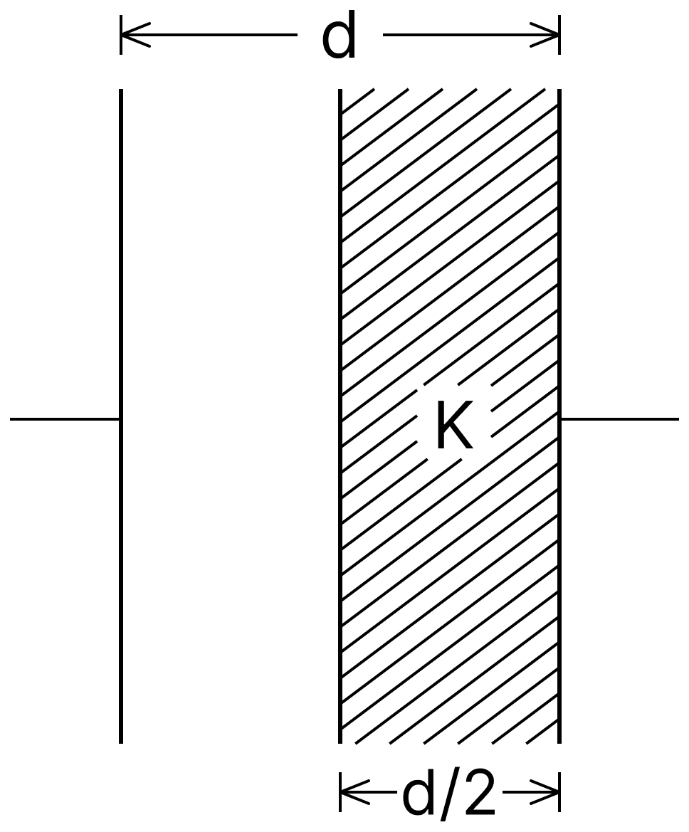
A parallel plate capacitor having cross-sectional area A and separation d has air in between the plates. Now, an insulating slab of same area but thickness d/2 is inserted between the plates as shown in figure having dielectric constant K (= 4). The ratio of new capacitance to its original capacitance will be :
- 4 : 1
- 2 : 1
- 8 : 5
- 6 : 5
Answer
8 : 5
Reason —
The original capacitance is C0 = ε0A/d. With a slab of thickness t = d/2 and dielectric constant K = 4 inserted,
Simplifying the denominator,
Hence
A capacitor C is fully charged with voltage V0. After disconnecting the voltage source, it is connected in parallel with another uncharged capacitor of capacitance . The energy loss in the process after the charge is distributed between the two capacitors is :
Answer
Reason —
The loss of energy when two capacitors at potentials V1 and V2 are joined in parallel is
Here C1 = C, C2 = C/2, V1 = V0 and V2 = 0. Substituting,
A parallel plate capacitor has plate of length 'l', width 'w' and separation of plates is 'd'. It is connected to a battery of emf V. A dielectric slab of the same thickness 'd' and of dielectric constant k = 4 is being inserted between the plates of the capacitor. At what length of the slab inside plates, will the energy stored in the capacitor be two times the initial energy stored?
Answer
Reason —
The battery remains connected, so V is constant and U = ½CV2 is proportional to the capacitance. For the energy to be doubled, the capacitance must be doubled.
Let a length x of the slab be inside the plates. The filled and the empty portions form two capacitors in parallel,
The initial capacitance is C0 = ε0wl/d. Setting C = 2C0,
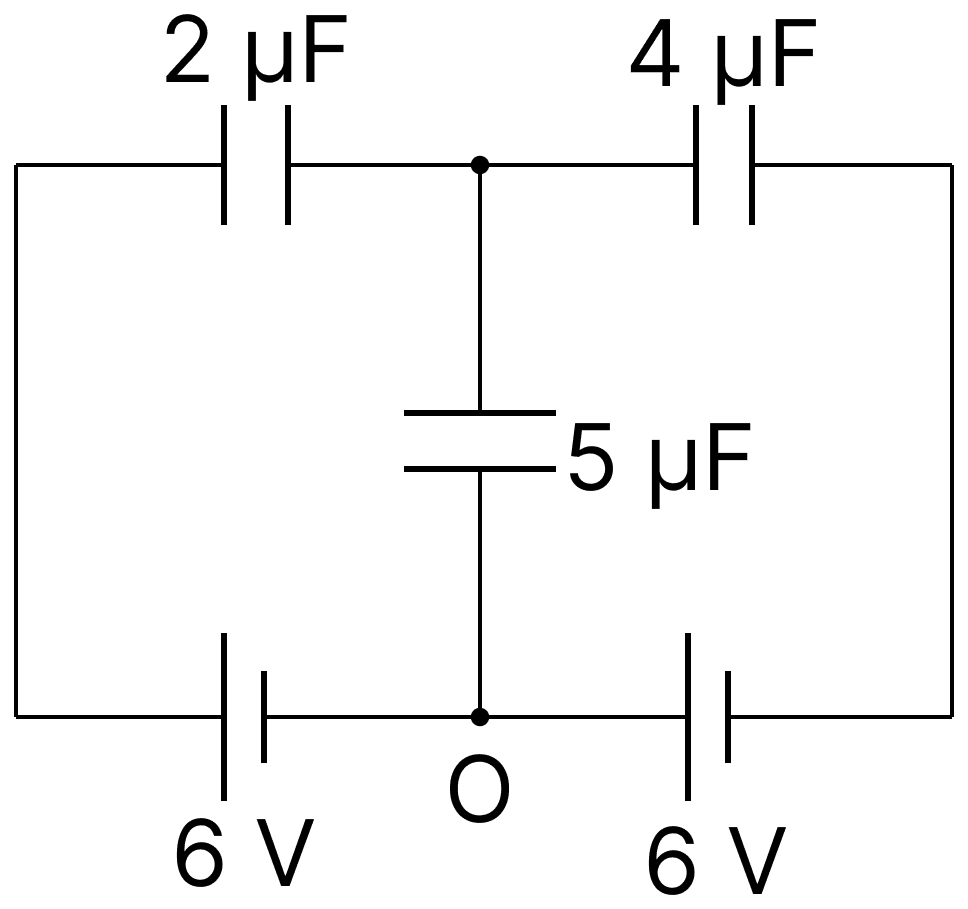
In the circuit shown, charge on the 5 µF capacitor is :
- 16.36 µC
- 18.00 µC
- 5.45 µC
- 10.90 µC
Answer
16.36 µC
Reason —
Let the potential of the common lower point O be zero. Both the 6 V cells raise the potentials of the two outer top corners to + 6 V each.
Let V be the potential of the junction to which the 2 µF, the 4 µF and the 5 µF capacitors are joined. Since this junction is isolated, the total charge on the plates meeting there is zero,
Hence the charge on the 5 µF capacitor is
Polar molecules are the molecules :
- having a permanent electric dipole moment
- having zero dipole moment
- acquire a dipole moment only in the presence of electric field due to displacement of charges
- acquire a dipole moment only when magnetic field is absent
Answer
having a permanent electric dipole moment
Reason —
In a polar molecule the centre of gravity of the positive charges does not coincide with that of the negative charges, so the molecule behaves as an electric dipole even in the absence of any external field, that is, it has a permanent electric dipole moment. Water and HCl are examples. A non-polar molecule, on the other hand, acquires a dipole moment only when an external field displaces its charges.
Two charged spherical conductors of radius R1 and R2 are connected by a wire. Then the ratio of surface charge densities of the spheres (σ1/σ2) is :
Answer
Reason —
On connecting by a wire, both spheres come to the same potential V,
In terms of the surface charge densities, Q = 4πR2σ, so
Equating the two expressions,
A parallel plate capacitor has a uniform electric field '' in the space between the plates. If the distance between the plates is 'd' and the area of each plate is 'A', the energy stored in the capacitor is (ε0 = permittivity of free space) :
Answer
Reason —
The energy stored per unit volume of the field, that is, the energy density, is
The field exists only in the space between the plates, whose volume is Ad. Hence the total energy stored is
The equivalent capacitance of the combination shown in the figure is :
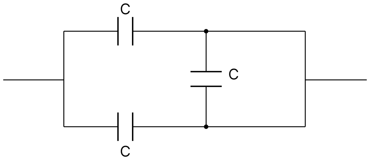
- 3C/2
- 3C
- 2C
- C/2
Answer
2C
Reason —
The two capacitors marked C in the upper and the lower arms are joined between the same pair of points, so they are in parallel, giving 2C.
The third capacitor C is connected across the two ends of the same right-hand junction, that is, both of its plates are joined to the same point by the connecting wires. It is therefore short-circuited and carries no charge (both sides of the vertical capacitor are at the same potential), so it does not contribute to the equivalent capacitance.
The material filled between the plates of a parallel plate capacitor has resistivity 200 Ω m. The value of capacitance of the capacitor is 2 pF. If a potential difference of 40 V is applied across the plates of the capacitor, then the value of leakage current flowing out of the capacitor is : (Given the value of relative permittivity of material is 50.)
- 0.9 mA
- 9.0 mA
- 9.0 µA
- 0.9 µA
Answer
0.9 mA
Reason —
Given, ρ = 200 Ω m, C = 2 pF = 2 × 10-12 F, V = 40 V and K = 50.
For the capacitor,
The resistance offered by the material between the plates is
Substituting the values,
Hence the leakage current is
A parallel plate capacitor with plate area A has separation d between the plates. Two dielectric slabs of dielectric constant K1 and K2 of same area A/2 and thickness d/2 are inserted in the space between the plates. The capacitance of the capacitor will be given by :
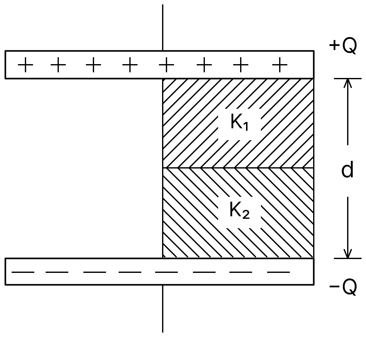
Answer
Reason —
The arrangement is equivalent to two capacitors in parallel, each of plate area A/2.
Left half (air throughout the gap d) :
Right half : here the two slabs, each of thickness d/2, lie one above the other, so they form two capacitors in series,
Adding the two parallel parts,
Three capacitors C1 = 2 µF, C2 = 6 µF and C3 = 12 µF are connected as shown in figure. Find the ratio of the charges on capacitors C1, C2 and C3 respectively.
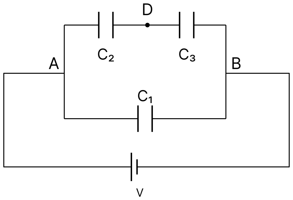
- 3 : 4 : 4
- 2 : 3 : 3
- 2 : 1 : 1
- 1 : 2 : 2
Answer
1 : 2 : 2
Reason —
From the figure, C2 and C3 are joined in series between A and B, and C1 is connected directly between A and B. The battery of emf V is applied across A and B.
Charge on C1 : it has the full potential difference V,
Charges on C2 and C3 : their series capacitance is
and being in series they carry equal charges,
Hence
A capacitor is connected to a 20 V battery through a resistance of 10 Ω. It is found that the potential difference across the capacitor rises to 2 V in 1 µs. The capacitance of the capacitor is ............... µF.
Given
- 0.95
- 9.52
- 1.85
- 0.105
Answer
0.95
Reason —
Given, V0 = 20 V, R = 10 Ω, V = 2 V at t = 1 µs = 10-6 s.
During charging through a resistance, the potential difference across the capacitor grows as
Substituting the values,
Taking the natural logarithm of both sides,
Hence
A parallel plate capacitor with plate area 'A' and distance of separation 'd' is filled with a dielectric. What is the capacity of the capacitor when permittivity of the dielectric varies as :
- 0
Answer
Reason —
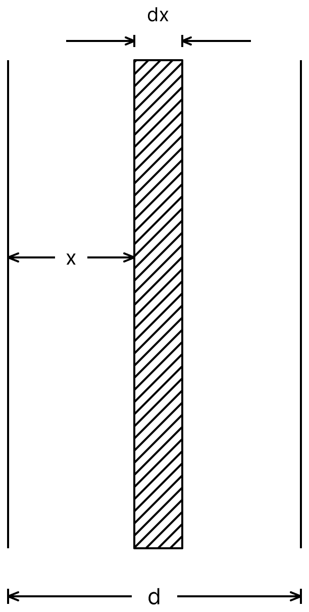
Consider a thin layer of thickness dx at a distance x from one plate. It behaves as an elementary capacitor of capacitance
All such layers are in series, so the reciprocals add,
Putting u = ε0 + kx, so that du = k dx,
By the symmetry of the given permittivity about x = d/2, the second half gives an equal contribution, so that
The two halves are themselves in series, hence
Two capacitors of capacities 2C and C are joined in parallel and charged up to potential V. The battery is removed and the capacitor of capacity C is filled completely with a medium of dielectric constant K. The potential difference across the capacitors will now be :
Answer
Reason —
In parallel the total capacitance is 2C + C = 3C, so the total charge stored is
The battery is then removed, so this charge is conserved. On filling the capacitor of capacity C with the dielectric, its capacitance becomes KC, and the total capacitance becomes
Hence the new common potential difference is
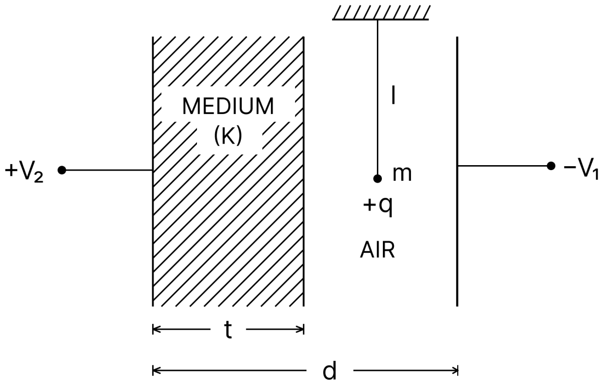
A simple pendulum of mass m, length l and charge '+q' suspended in the electric field produced by two conducting parallel plates as shown. The value of deflection of pendulum in equilibrium position will be :
Answer
Reason —
The plates are at potentials + V2 and − V1, so the total potential difference between them is V1 + V2.
The gap of width d contains a dielectric slab of thickness t and an air region of width (d − t). These two portions form two capacitors in series; let C1 be the capacitance of the air portion, in which the bob hangs, and C2 that of the dielectric portion. In a series combination the potential difference divides in the inverse ratio of the capacitances, so the part appearing across the air region is
The field acting on the bob is therefore
In the equilibrium position the string makes an angle θ with the vertical such that the horizontal electric force balances the horizontal component of the tension,
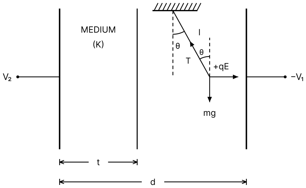
Note: The figure does not label which of C1 and C2 belongs to which region. The printed answer corresponds to taking C1 as the capacitance of the air portion and C2 as that of the dielectric portion.
For changing the capacitance of a given parallel plate capacitor, a dielectric material of dielectric constant K is used, which has the same area as the plates of the capacitor. The thickness of the dielectric slab is , where 'd' is the separation between the plates of parallel plate capacitor. The new capacitance (C') in terms of original capacitance (C0) is given by the following relation.
Answer
Reason —
With a slab of thickness t and dielectric constant K inserted,
Putting t = 3d/4,
An electron with kinetic energy K1 enters between parallel plates of a capacitor at an angle 'α' with the plates. It leaves the plates at angle 'β' with kinetic energy K2. Then the ratio of kinetic energies K1 : K2 will be :
Answer
Reason —
The electric field between the plates is perpendicular to the plates, so the electron experiences a force only in that direction. The component of its velocity parallel to the plates therefore remains unchanged.
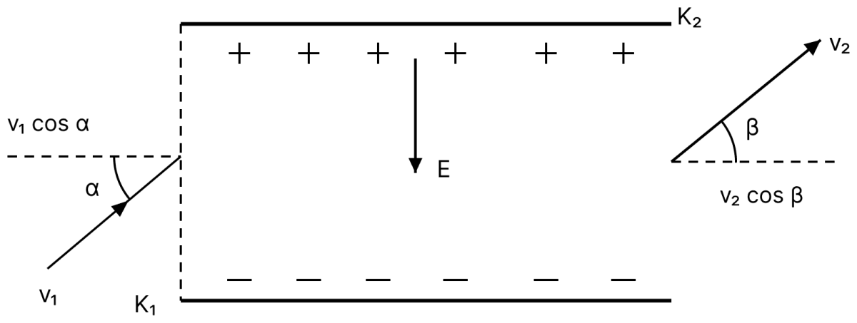
If v1 and v2 are the speeds at entry and exit, then
Since the kinetic energy is proportional to the square of the speed,
A parallel plate capacitor is formed by two plates each of area 30π cm2, separated by 1 mm. A material of dielectric strength 3.6 × 10⁷ Vm-1 is filled between the plates. If the maximum charge that can be stored on the capacitor without causing any dielectric breakdown is 7 × 10⁻⁶ C, the value of dielectric constant of the material is :
- 1.66
- 1.75
- 2.25
- 2.33
Answer
2.33
Reason —
Given,
- A = 30π cm2 = 30π × 10-4 m2, d = 1 mm = 10-3 m
- Dielectric strength, Emax = 3.6 × 10⁷ V m-1
- Qmax = 7 × 10⁻⁶ C
The maximum permissible potential difference is
Hence the capacitance is
Now C = Kε0A/d, so
With ε0 = 8.85 × 10⁻¹² C2 N-1 m-2,
If the charge on a capacitor is increased by 2 C, the energy stored in it increases by 44%. The original charge on the capacitor is (in C) :
- 10
- 20
- 30
- 40
Answer
10
Reason —
The energy stored is U = q2/2C, so for a given capacitor U ∝ q2.
Let the original charge be q. When it becomes q + 2, the energy becomes 1.44 times its original value,
Taking the square root of both sides,
Two metallic plates form a parallel plate capacitor. The distance between the plates is 'd'. A metal sheet of thickness and of area equal to area of each plate is introduced between the plates. What will be the ratio of the new capacitance to the original capacitance of the capacitor?
- 2 : 1
- 1 : 2
- 1 : 4
- 4 : 1
Answer
2 : 1
Reason —
For a slab of thickness t and dielectric constant K,
For a metal sheet K = ∞, so t/K = 0. With t = d/2,
Hence the new capacitance is twice the original one, that is, 2 : 1.
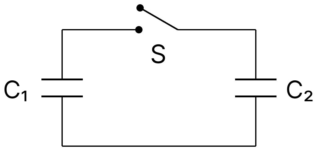
Two capacitors having capacitance C1 and C2 respectively are connected as shown in figure. Initially, capacitor C1 is charged to a potential difference V volt by a battery. The battery is then removed and the charged capacitor C1 is now connected to uncharged capacitor C2 by closing the switch S. The amount of charge on the capacitor C2 after equilibrium, is :
Answer
Reason —
The initial charge on C1 is Q = C1V. The battery is removed, so on closing the switch this charge is merely shared between the two capacitors, which are then in parallel. The common potential difference is
Hence the charge on C2 is
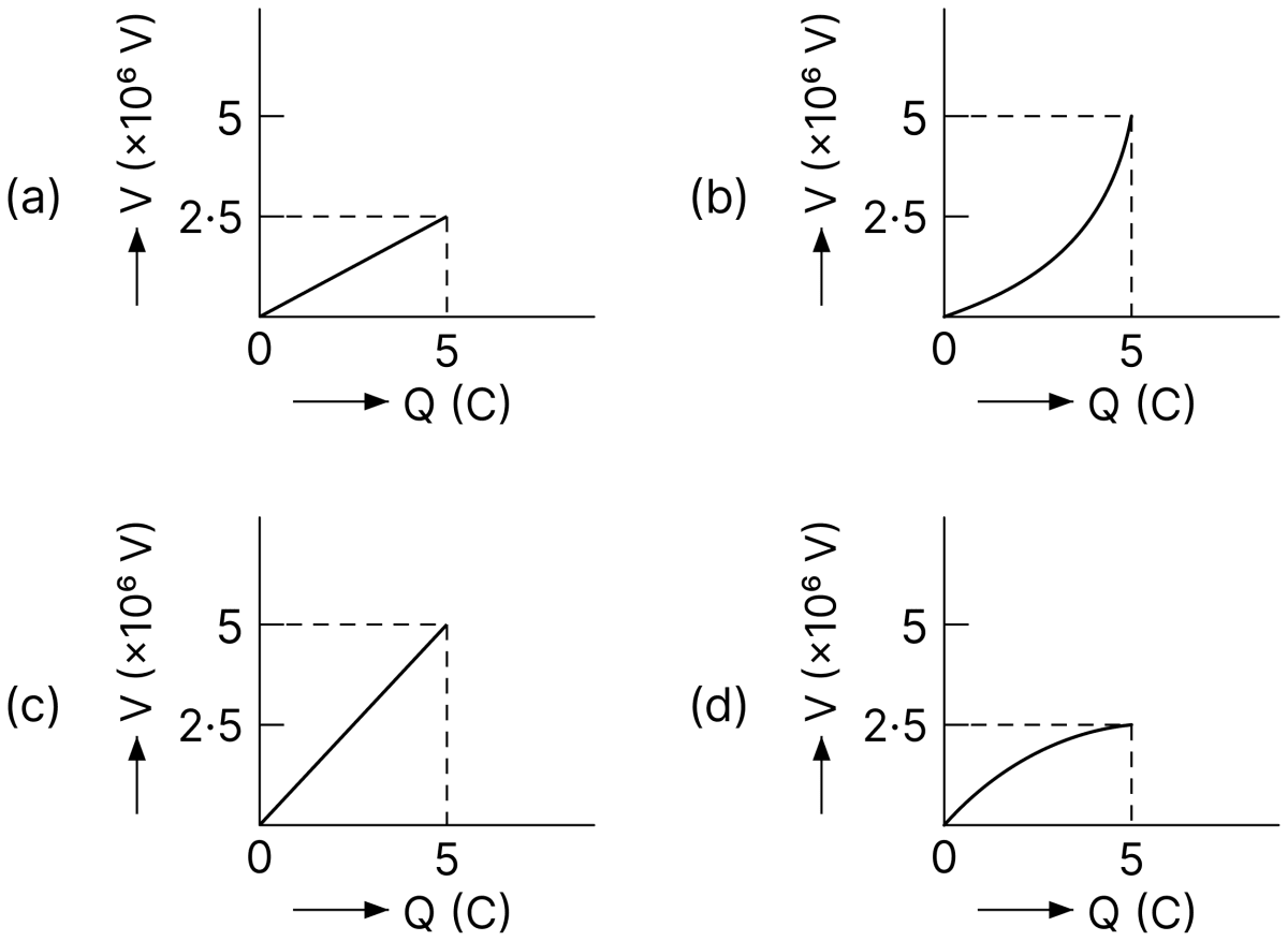
A condenser of 2 µF capacitance is charged steadily from 0 to 5 C. Which of the following graph represents correctly the variation of potential difference (V) across its plates with respect to the charge (Q) on the condenser?
Answer
Graph (a)
Reason —
For a capacitor of fixed capacitance,
so V is directly proportional to Q, and the graph must be a straight line passing through the origin. When Q reaches its final value of 5 C,
The only graph which is a straight line through the origin ending at 2.5 × 10⁶ V for Q = 5 C is graph (a).
Note: The answer printed in the textbook is (d), which shows a curved graph saturating at 5 × 10⁶ V. This contradicts the relation V = Q/C, which requires a straight line reaching 2.5 × 10⁶ V. The correct option is (a).
Capacitance of an isolated conducting sphere of radius R1 becomes n times when it is enclosed by a concentric conduction sphere of radius R2 connected to earth. The ratio of their radii is :
Answer
Reason —
The capacitance of the isolated sphere is
When it is enclosed by a concentric earthed sphere of radius R2, the arrangement becomes a spherical capacitor of capacitance
It is given that C = nC0, so
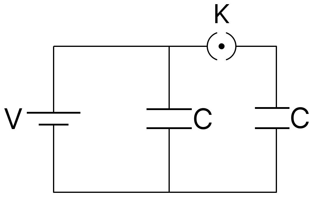
A source of potential difference V is connected to the combination of two identical capacitors as shown in the figure. When key K is closed, the total energy stored across the combination is E1. Now key K is opened and dielectric of dielectric constant 5 is introduced between the plates of the capacitors. The total energy stored across the combination is E2. The ratio E1/E2 will be :
Answer
Reason —
With the key K closed, both identical capacitors of capacitance C are in parallel across the source, so
and the charge on each is CV.
When K is opened, one capacitor remains connected to the source while the other is isolated with its charge CV. The dielectric of K = 5 is then introduced in both, so each capacitance becomes 5C.
Capacitor still connected to the source : the potential difference stays V,
Isolated capacitor : the charge stays CV,
Hence
Two capacitors, each having capacitance 40 µF are connected in series. The space between one of the capacitors is filled with dielectric material of dielectric constant K such that the equivalence capacitance of the system became 24 µF. The value of K will be :
- 1.5
- 2.5
- 1.2
- 3
Answer
1.5
Reason —
Given, C1 = 40 µF and C2 = 40K µF after filling one of them with the dielectric, and Ceq = 24 µF.
For a series combination,
Two identical thin metal plates has charge q1 and q2 respectively such that q1 > q2. The plates were brought close to each other to form a parallel plate capacitor of capacitance C. The potential difference between them is :
Answer
Reason —
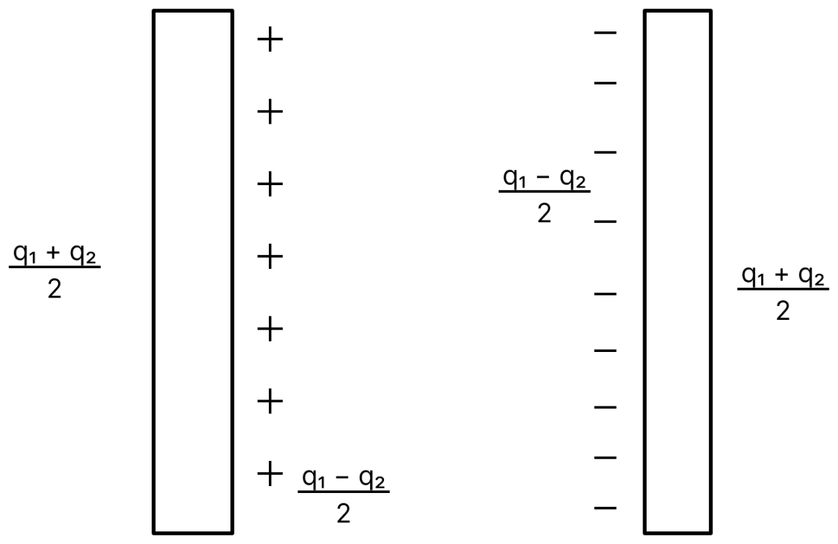
When two plates carrying unequal charges are brought close together, the charge distributes itself so that the facing surfaces carry and the outer surfaces carry each.
Only the charge on the facing surfaces produces the field in the gap, so the effective charge of the capacitor is
Hence the potential difference is
A medium having dielectric constant K > 1 fills the space between the plates of a parallel plate capacitor. The plates have large area, and the distance between them is d. The capacitor is connected to a battery of voltage V, as shown in Fig. (a). Now, both the plates are moved by a distance of from their original positions, as shown in Fig. (b).
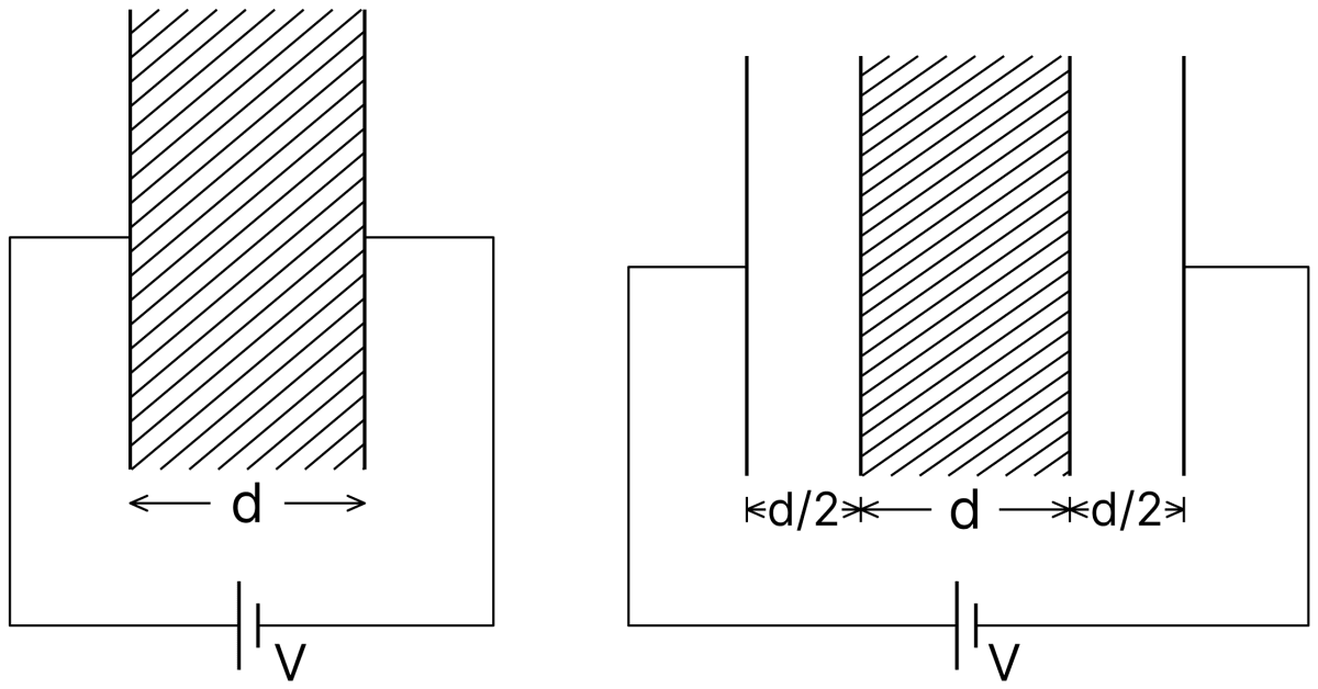
In the process of going from the configuration depicted in Fig. (a) to that in Fig. (b), which of the following statement(s) is(are) correct?
- The electric field inside the dielectric material is reduced by a factor of 2K.
- The capacitance is decreased by a factor of .
- The voltage between the capacitor plates is increased by a factor of (K + 1).
- The work done in the process does not depend on the presence of the dielectric material.
Answer
The capacitance is decreased by a factor of .
Reason —
Initially : the dielectric fills the whole gap d, so
Finally : the separation becomes 2d, of which a thickness d is the dielectric and the remaining d is air. These form two capacitors in series,
Therefore
so the capacitance is decreased by the factor 1/(K + 1), which makes the second statement correct. The battery remains connected, so the voltage between the plates stays V and the third statement is wrong. Since the field inside the dielectric is not reduced by a factor 2K, and the work done clearly involves K through the change in capacitance, the first and the fourth statements are also wrong.
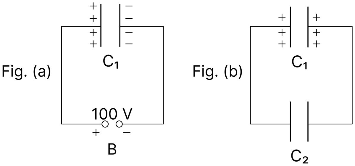
A capacitor of capacitance C1 = 900 pF is charged fully by 100 V battery B as shown in Fig. (a). Then it is disconnected from the battery and connected to another uncharged capacitor of capacitance C2 = 900 pF as shown in Fig. (b). The electrostatic energy stored by the system shown in fig. (b) is :
- 1.5 × 10⁻⁶ J
- 4.5 × 10⁻⁶ J
- 3.25 × 10⁻⁶ J
- 2.25 × 10⁻⁶ J
Answer
2.25 × 10⁻⁶ J
Reason —
The charge on C1 before connecting is
The battery is disconnected, so this charge is shared between the two equal capacitors joined in parallel. The common potential difference is
The energy stored by the system is
A capacitor of capacitance C is charged to a potential V. The flux of the electric field through a closed surface enclosing the positive plate of the capacitor is :
- Zero
Answer
Reason —
By Gauss's theorem, the flux of the electric field through a closed surface is
The closed surface encloses only the positive plate, whose charge is
Hence
Given below are two statements : One is labelled as Assertion (A) and the other is labelled as Reason (R).
Assertion (A): Two metallic spheres are charged to the same potential. One of them is hollow and another is solid, and both have the same radii. Solid sphere will have lower charge than the hollow one.
Reason (R): Capacitance of metallic spheres depend on the radii of spheres.
In the light of above statements, choose the most appropriate answer the from options given below.
- Both (A) and (R) are true and (R) is the correct explanation of (A).
- Both (A) and (R) are true but (R) is not the correct explanation of (A).
- (A) is true but (R) is false.
- (A) is false but (R) is true.
Answer
(A) is false but (R) is true.
Reason —
The charge given to a conductor resides entirely on its outer surface, so it makes no difference whether the sphere is solid or hollow. The capacitance of either is
which depends only on the radius. Since the two spheres have equal radii, they have equal capacitances, and being at the same potential they carry equal charges. Hence the assertion is false.
The reason, however, is a correct statement, since the capacitance of a metallic sphere does depend on its radius.
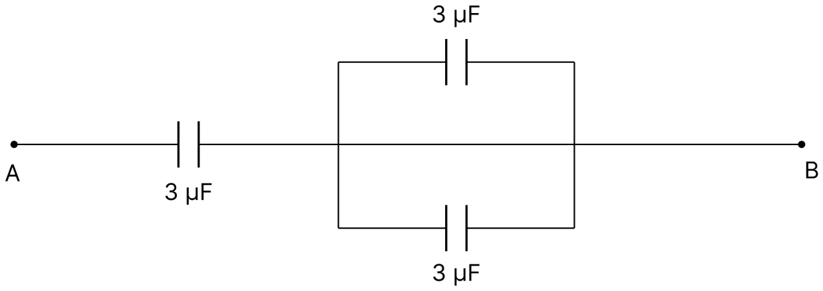
The equivalent capacitance of the system shown in the following circuit is :
- 6 µF
- 9 µF
- 2 µF
- 3 µF
Answer
2 µF
Reason —
The two 3 µF capacitors on the right are joined between the same pair of points, so they are in parallel,
This combination is in series with the 3 µF capacitor on the left,
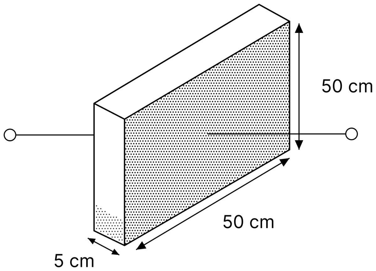
A container has a base of 50 cm × 5 cm and height 50 cm, as shown in the figure. It has two parallel electrically conducting walls each of area 50 cm × 50 cm. The remaining walls of the container are thin and non-conducting. The container is being filled with a liquid of dielectric constant 3 at a uniform rate of 250 cm3 s-1. What is the value of the capacitance of the container after 10 seconds?
[Given : Permittivity of free space ε0 = 9 × 10-12 C2N-1m-2, the effects of the non-conducting walls on the capacitance are negligible]
- 27 pF
- 63 pF
- 81 pF
- 135 pF
Answer
63 pF
Reason —
Given, the conducting walls each of area 50 cm × 50 cm are 5 cm apart, so d = 5 cm = 0.05 m.
Volume of liquid poured in 10 s,
The base area is 50 × 5 = 250 cm2, so the height of the liquid is
The filled and the empty portions form two capacitors in parallel, since the liquid rises across the full separation between the two walls.
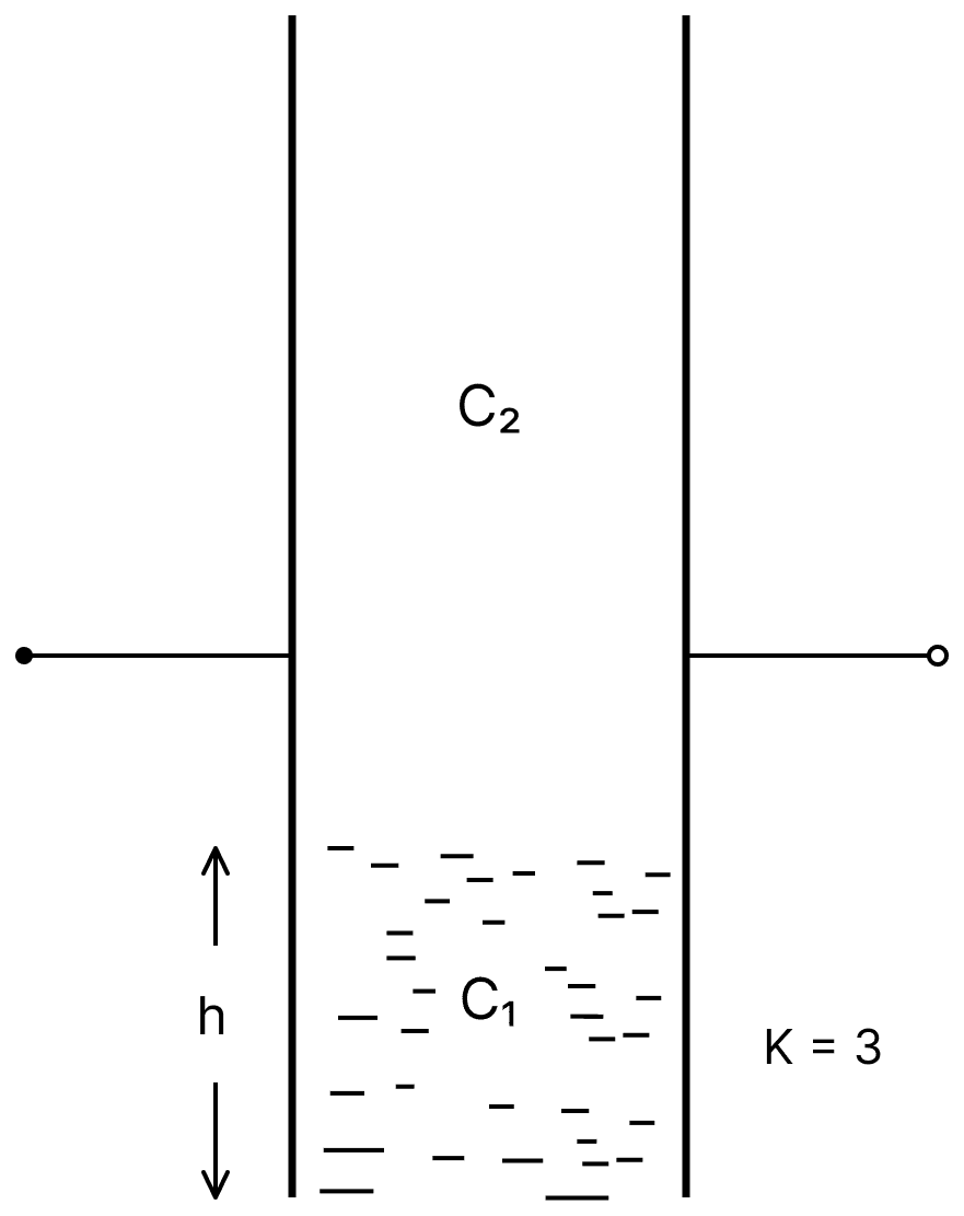
Filled portion : area 50 cm × 10 cm = 500 cm2 = 0.05 m2,
Empty portion : area 50 cm × 40 cm = 2000 cm2 = 0.2 m2,
Hence
A capacitor has air as dielectric medium and two conducting plates of area 12 cm2 and they are 0.6 cm apart. When a slab of dielectric having area 12 cm2 and 0.6 cm thickness is inserted between the plates, one of the conducting plates has to be moved by 0.2 cm to keep the capacitance same as in previous case. The dielectric constant of the slab is : (Given ε0 = 8.834 × 10⁻¹² F/m)
- 1.50
- 1.33
- 0.66
- 1
Answer
1.50
Reason —
Initially the capacitance is
The slab of thickness t = 0.6 cm fills the whole original gap, and the plate is then moved out by 0.2 cm, so the new separation is d' = 0.8 cm. With the slab inside,
For the capacitance to remain the same,
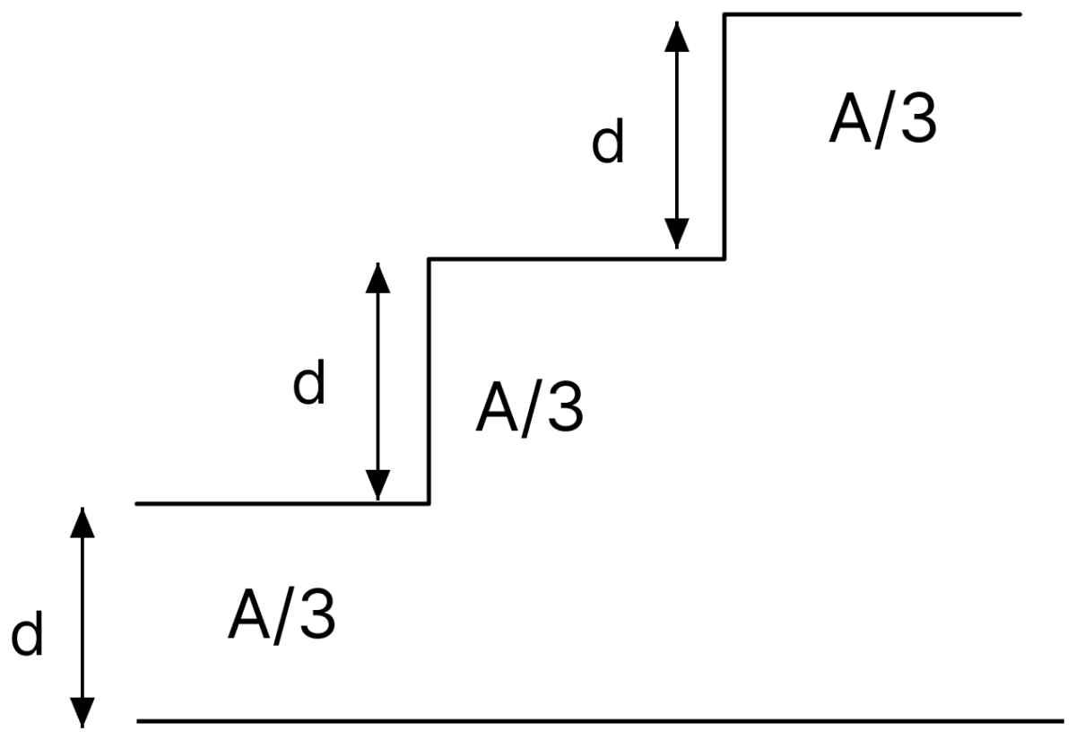
A capacitor is made of a flat plate of area A and a second plate having a stair-like structure as shown in figure. If the area of each stair is A/3 and the height is d, the capacitance of the arrangement is :
Answer
Reason —
The three stairs lie at distances d, 2d and 3d from the flat plate, and each has area A/3. They behave as three capacitors joined in parallel,
Note: In the textbook, options (c) and (d) both print , which is a printing error. The correct answer, option (a), is unaffected.
Four identical thin, square metal sheets, S1, S2, S3 and S4, each of side a are kept parallel to each other with equal distance d(<< a) between them, as shown in the figure. Let C0 = ε0a2/d, where ε0 is the permittivity of free space.
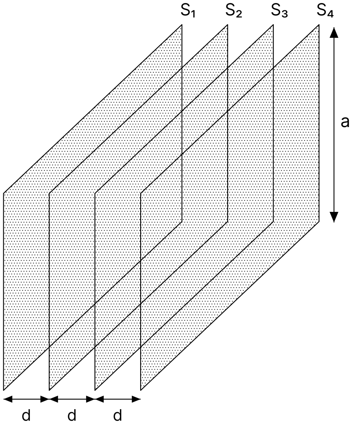
Match the quantities mentioned in List-I with their values in List-II and choose the correct option.
| List-I | List-II |
|---|---|
| (P) The capacitance between S1 and S4, with S2 and S3 not connected, is | (1) 3C0 |
| (Q) The capacitance between S1 and S4, with S2 shorted to S3, is | (2) C0/2 |
| (R) The capacitance between S1 and S3, with S2 shorted to S4, is | (3) C0/3 |
| (S) The capacitance between S1 and S2, with S3 shorted to S1, and S2 shorted to S4, is | (4) 2C0/3 |
| (5) 2C0 |
- P → 3; Q → 2; R → 4; S → 5
- P → 2; Q → 3; R → 2; S → 1
- P → 3; Q → 2; R → 4; S → 1
- P → 3; Q → 2; R → 2; S → 5
Answer
P → 3; Q → 2; R → 4; S → 1
Reason —
Each adjacent pair of sheets forms a capacitor of capacitance C0 = ε0a2/d.
(P) With S2 and S3 unconnected, the three gaps S1–S2, S2–S3 and S3–S4 are in series,
(Q) Shorting S2 to S3 removes the middle gap, leaving only the gaps S1–S2 and S3–S4 in series,
(R) With S2 shorted to S4, the gap S3–S4 comes in parallel with the gap S2–S3, giving 2C0, and this is in series with the gap S1–S2,
(S) With S3 shorted to S1 and S2 shorted to S4, all the three gaps lie between the same pair of nodes and are in parallel,
If the plates of a parallel plate capacitor connected to a battery are moved close to each other, then
A. the charge stored in it, increases.
B. the energy stored in it, decreases.
C. its capacitance increases.
D. the ratio of charge to its potential remains the same.
E. the product of charge and voltage increases.
Choose the most appropriate answer from the options given below.
- A, B and E only
- A, C and E only
- B, D and E only
- A, B and C only
Answer
A, C and E only
Reason —
The battery remains connected, so the potential difference V is constant. On bringing the plates closer, d decreases and hence
so statement C is correct, and statement D is wrong since Q/V = C has changed.
Since Q = CV with V fixed, the charge increases, so statement A is correct.
The energy stored is U = ½CV2, which increases with C, so statement B is wrong. The product QV = CV2 also increases, so statement E is correct.
Hence only A, C and E are correct.
A 5 µF capacitor is charged fully by a 220 V supply. It is then disconnected from the supply and is connected in series to another uncharged 2.5 µF capacitor. If the energy change during the charge redistribution is J then value of X to the nearest integer is ............... .
Answer
Given,
- C1 = 5 µF = 5 × 10⁻⁶ F, charged to V1 = 220 V
- C2 = 2.5 µF = 2.5 × 10⁻⁶ F, uncharged, so V2 = 0
The supply is disconnected, so the charge on the first capacitor is merely redistributed between the two. The loss of energy in such a redistribution is
Substituting the values,
Hence, X = 4.
Note: The question states that the second capacitor is connected "in series". A capacitor joined in series with a charged one cannot receive any redistributed charge, so no energy change would occur. The printed answer follows from the two capacitors being joined in parallel, and the word "series" is a misprint.
A parallel plate capacitor has plate area 100 m2 and plate separation of 10 m. The space between the plates is filled upto a thickness 5 m with a material of dielectric constant of 10. The resultant capacitance of the system is x pF. The value of ε0 = 8.85 × 10⁻¹² fm-1. The value of x to the nearest integer is ............... .
Answer
Given,
- Plate area, A = 100 m2
- Plate separation, d = 10 m
- Thickness of the dielectric, t = 5 m, with K = 10
- ε0 = 8.85 × 10⁻¹² F m-1
When a slab of thickness t and dielectric constant K partly fills the gap,
Substituting the values,
Hence, x = 161.
In the circuit shown below, the switch S is connected to position P for a long time so that the charge on the capacitor becomes q1 µC. Then S is switched to position Q. After a long time, the charge on the capacitor is q2 µC.
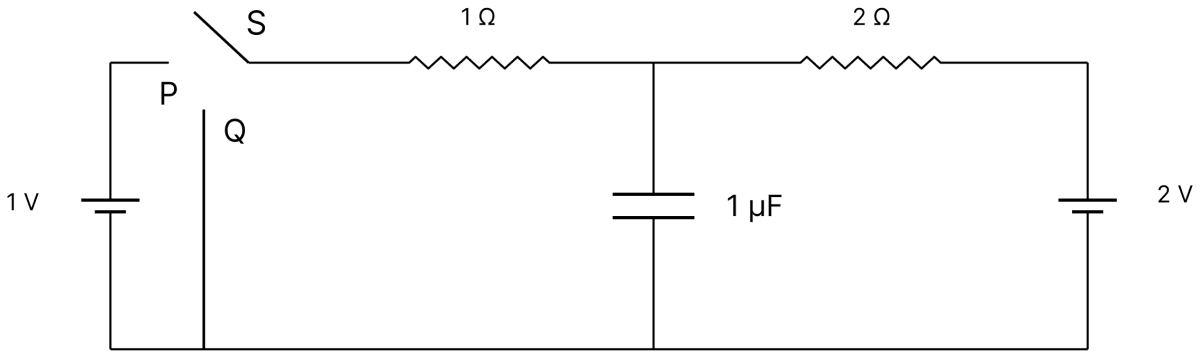
The magnitude of q1 is ............... .
Answer
Given,
- Capacitance, C = 1 µF
- With S at P, the 1 V cell and the 2 V cell are joined through the 1 Ω and the 2 Ω resistors
After a long time the capacitor is fully charged, so no current flows into its branch. A steady current, however, flows round the loop containing the two cells,
Taking the lower rail as the zero of potential, the potential of the junction to which the capacitor is joined is obtained by starting from the 2 V cell and subtracting the drop across the 2 Ω resistor,
Hence the charge on the capacitor is
Hence, the magnitude of q1 is 1.33 µC.
In the circuit shown below, the switch S is connected to position P for a long time so that the charge on the capacitor becomes q1 µC. Then S is switched to position Q. After a long time, the charge on the capacitor is q2 µC.
The magnitude of q2 is ............... .
Answer
Given,
- Capacitance, C = 1 µF
- With S at Q, the 1 V cell is cut out and the 1 Ω resistor is joined directly to the lower rail
Again no current flows into the capacitor branch in the steady state, but a current flows in the loop containing the 2 V cell, the 2 Ω resistor and the 1 Ω resistor,
The potential of the junction to which the capacitor is joined is the drop across the 1 Ω resistor,
Hence
Hence, the magnitude of q2 is 0.67 µC.
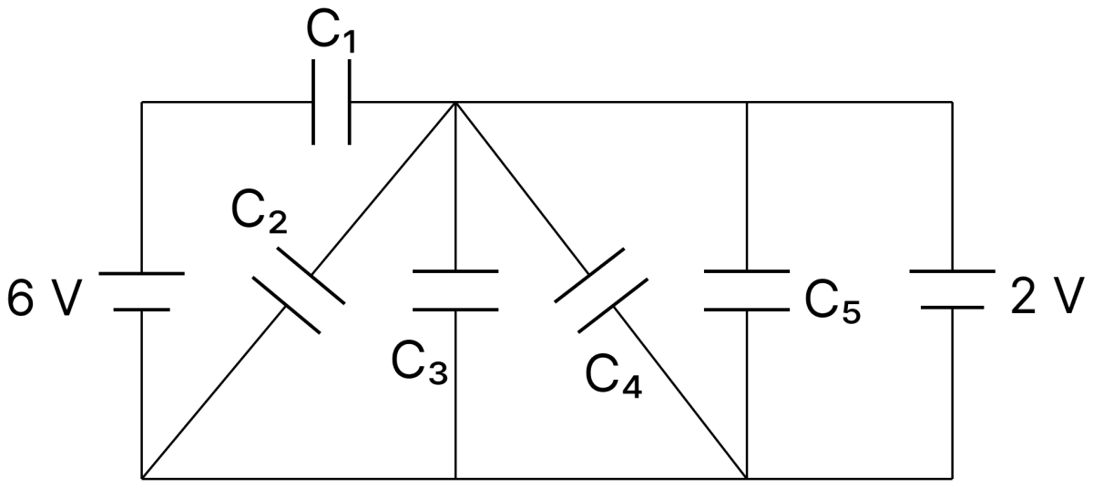
In the following circuit C1 = 12 µF, C2 = C3 = 4 µF and C4 = C5 = 2 µF. The charge stored in C3 is ............... µC.
Answer
Given,
- C1 = 12 µF, C2 = C3 = 4 µF, C4 = C5 = 2 µF
- The cells in the circuit are of 6 V and 2 V
Let the lower rail be taken as the zero of potential.
The upper rail is continuous from the junction of C1, C2, C3 and C4 right up to the positive terminal of the 2 V cell. Hence this junction is held at
The capacitor C3 is joined between this junction and the lower rail, so the potential difference across it is 2 V. Therefore
Hence, the charge stored in C3 is 8.00 µC.
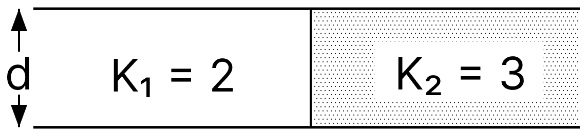
A capacitor of 10 µF capacitance whose plates are separated by 10 mm through air and each plate has area 4 cm2 is now filled equally with two dielectric media of K1 = 2, K2 = 3 respectively as shown in figure. If new force between the plates is 8 N, the supply voltage is ........ V.
Answer
Given,
- Capacitance with air, C = 10 µF = 10 × 10-6 F
- Separation between the plates, d = 10 mm = 1 × 10⁻² m
- Area of each plate, A = 4 cm2 = 4 × 10⁻⁴ m2
- Dielectric constants, K1 = 2 and K2 = 3, each occupying half the plate area
- New force between the plates, F = 8 N
The two dielectrics occupy the two halves of the plate area, each of area A/2 with the full separation d, so they behave as two capacitors joined in parallel. Their capacitances are
If V is the supply voltage, the charges on the two halves are
The force between the plates of a charged parallel-plate capacitor is half the product of the charge on a plate and the electric field between the plates,
Both halves have the same potential difference V across the same separation d, so the field in each half is
The total force on a plate is the sum of the forces on its two halves,
Substituting the charges, d = 1 × 10⁻² m and F = 8 N,
Hence, the supply voltage is 80 V.
Note: The textbook gives 0.93 × 10⁻² V because it applies the air-capacitor relation F = Q2/2Aε0 to the dielectric-filled halves. The stated 10 µF also conflicts with A = 4 cm2 and d = 10 mm, which give ε0A/d = 3.54 × 10⁻¹³ F; 80 V follows when the stated capacitance is taken as intended.