
The potential difference of a cell in an open-circuit is 6 V which falls to 4 V when a current of 2 A is drawn from the cell. Calculate the emf and internal resistance of the cell.
Answer
Given,
- Potential difference in open circuit = 6 V
- Terminal potential difference, V = 4 V
- Current drawn, I = 2 A
In an open circuit no current is drawn from the cell, so the terminal potential difference is equal to the emf of the cell.
When a current I is drawn, the terminal potential difference is
Hence, the emf of the cell is 6 V and its internal resistance is 1 Ω.
The emf of a cell is 2.0 V. When it is connected to a 25 Ω resistor, the terminal voltage of the cell is found to be 1.8 V. What is the internal resistance of the cell and the current in 25 Ω resistor?
Answer
Given,
- Emf of the cell, E = 2.0 V
- External resistance, R = 25 Ω
- Terminal voltage, V = 1.8 V
The terminal voltage is the potential drop across the external resistance,
The internal resistance is obtained from V = E − Ir,
Hence, the internal resistance of the cell is 2.78 Ω and the current in the 25 Ω resistor is 0.072 A.
The potential difference across a cell is 1.8 V when a current of 0.5 A is drawn from it. The PD falls to 1.6 V when a current of 1.0 A is drawn. Find the emf and the internal resistance of the cell.
Answer
Given,
- V1 = 1.8 V when I1 = 0.5 A
- V2 = 1.6 V when I2 = 1.0 A
Using V = E − Ir for both cases,
Subtracting Eq. (ii) from Eq. (i),
Substituting r = 0.4 Ω in Eq. (i),
Hence, the emf of the cell is 2.0 V and its internal resistance is 0.4 Ω.
A 200 Ω resistor, a voltmeter and a 2.0 V cell of negligible internal resistance are connected in series. The voltmeter reads 1.0 V. Find the resistance of the voltmeter and the current in the circuit.
Answer
Given,
- R = 200 Ω
- E = 2.0 V, internal resistance negligible
- Reading of the voltmeter = 1.0 V
The voltmeter is in series with the resistor, so the sum of the potential drops across the two equals the emf of the cell. Hence the potential drop across the 200 Ω resistor is
The current in the circuit is
The same current flows through the voltmeter, so its resistance is
Hence, the resistance of the voltmeter is 200 Ω and the current in the circuit is 5 × 10⁻³ A.
A high-resistance voltmeter connected across the terminals of a battery reads 15 V. When an ammeter is included in the circuit, the voltmeter reads 9.0 V and the ammeter reads 1.5 A. Find (i) internal resistance of the battery and (ii) resistance of ammeter plus the connecting wires.
Answer
Given,
- Reading of the voltmeter alone = 15 V
- Reading of the voltmeter with the ammeter in the circuit, V = 9.0 V
- Reading of the ammeter, I = 1.5 A
A high-resistance voltmeter draws practically no current, so in the first case the reading gives the emf of the battery,
(i) Internal resistance :
(ii) Resistance of the ammeter and the connecting wires : The terminal potential difference of 9.0 V appears across them, so
Hence, the internal resistance of the battery is 4.0 Ω and the resistance of the ammeter plus the connecting wires is 6.0 Ω.
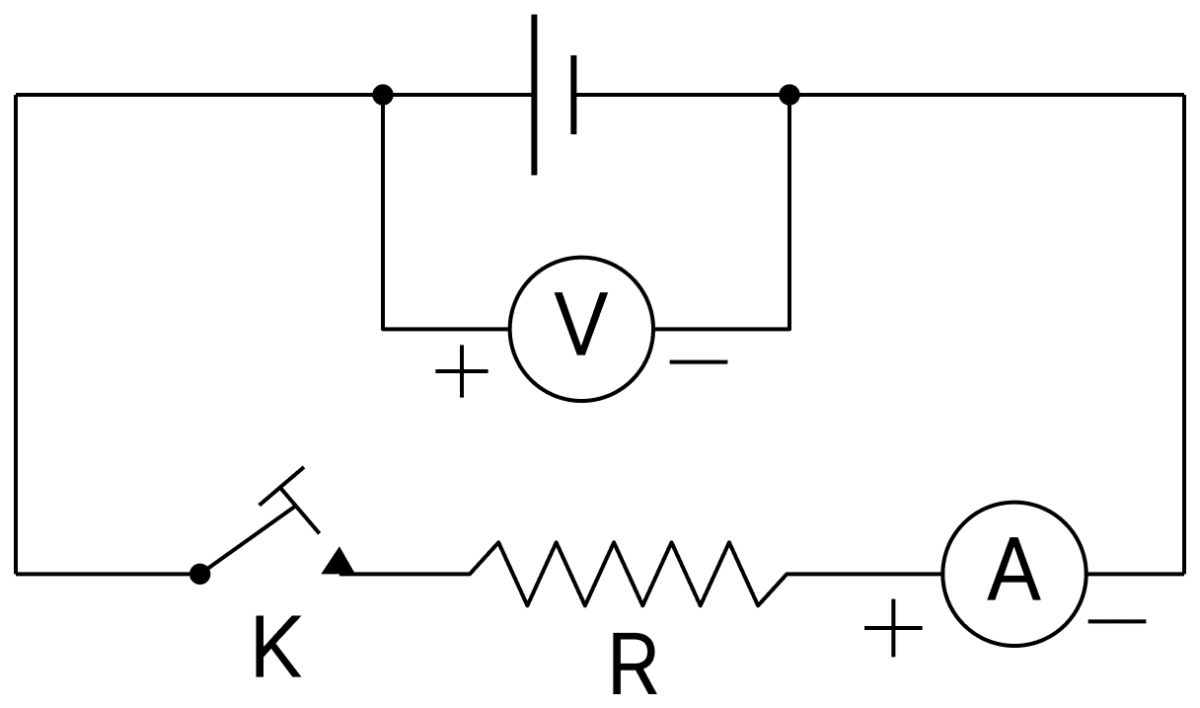
In the circuit shown, the resistance of the ammeter A is negligible and that of the voltmeter V is very high. When the key K is open, the reading of voltmeter is 1.53 V. On closing the key, the reading of ammeter is 1.00 A and that of the voltmeter drops to 1.03 V. Calculate : (i) emf of the cell, (ii) internal resistance of the cell, (iii) value of R.
Answer
Given,
- Reading of the voltmeter with K open = 1.53 V
- Reading of the ammeter with K closed, I = 1.00 A
- Reading of the voltmeter with K closed, V = 1.03 V
(i) Emf of the cell : With the key open no current is drawn from the cell, because the voltmeter has a very high resistance. Hence the voltmeter reads the emf itself,
(ii) Internal resistance : With the key closed,
(iii) Value of R : The terminal potential difference appears across R,
Hence, E = 1.53 V, r = 0.50 Ω and R = 1.03 Ω.
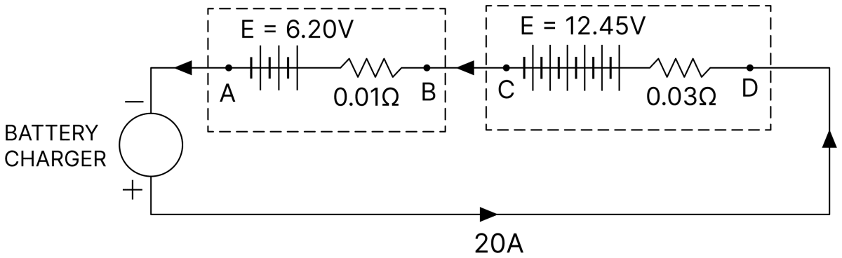
Two batteries of emfs 6.20 V and 12.45 V and internal resistances 0.01 Ω and 0.03 Ω respectively are being charged by a battery charger which supplies a current of 20 A. What are the terminal potential differences of the batteries during charging?
Answer
Given,
- E1 = 6.20 V, r1 = 0.01 Ω
- E2 = 12.45 V, r2 = 0.03 Ω
- Charging current, I = 20 A
During charging the current is sent into the battery from outside, so the potential drop Ir is added to the emf and the terminal potential difference is
For the first battery :
For the second battery :
Hence, the terminal potential differences are 6.40 V and 13.05 V.
Two cells, each of emf 1.5 V are joined in series and send 1.0 A current in an external resistor. If the same cells are joined in parallel, then they send 0.6 A current in the same resistor. What is the internal resistance of each cell?
Answer
Given,
- Emf of each cell, E = 1.5 V
- Current in series combination, Is = 1.0 A
- Current in parallel combination, Ip = 0.6 A
In series, the net emf is 2E and the total internal resistance is 2r,
In parallel, the net emf is E and the total internal resistance is r/2,
Subtracting Eq. (ii) from Eq. (i),
Hence, the internal resistance of each cell is Ω.
Two identical cells, whether joined together in series or in parallel, give the same current when connected to an external resistance of 1 Ω. Find internal resistance of each cell.
Answer
Given,
- External resistance, R = 1 Ω
- Current in series = current in parallel
For two identical cells of emf E and internal resistance r,
Equating the two currents,
Hence, the internal resistance of each cell is 1 Ω.
50 bulbs are joined in parallel, each being a 100 V bulb taking a current of 0.6 A. A battery of 54 accumulators, each of emf 2 V and internal resistance 0.005 Ω, is used to light up the bulbs. Will the bulbs be properly lighted, over-lit or under-lit?
Answer
Given,
- Number of bulbs = 50, each 100 V taking 0.6 A
- Number of accumulators = 54, each of emf 2 V and internal resistance 0.005 Ω
Requirement of the bulbs : The bulbs are in parallel, so the total current required, at a potential difference of 100 V, is
The resistance of one bulb is 100/0.6 Ω, so the resistance of the parallel combination is
Supply from the battery : The 54 accumulators are in series, so
The potential difference across the bulbs is
Hence, the bulbs will be properly lighted, because the battery gives 30 A at 100 V and the bulbs also require exactly 30 A at 100 V.
(i) Three cells of emfs 2.0 V , 1.8 V and 1.5 V and internal resistances 0.05 Ω , 0.7 Ω and 1.0 Ω, respectively are joined in series. This battery is connected to an external resistor of 4.0 Ω, through a low-resistance ammeter. What would the ammeter read?
(ii) If these cells are joined in parallel, can the battery so formed may give a definite emf and internal resistance?
Answer
Given,
- E1 = 2.0 V, r1 = 0.05 Ω
- E2 = 1.8 V, r2 = 0.7 Ω
- E3 = 1.5 V, r3 = 1.0 Ω
- External resistance, R = 4.0 Ω
(i) In a series combination the emfs add up and so do the internal resistances,
The ammeter is of low resistance, so
Hence, the ammeter would read 0.92 A.
(ii) No. For non-similar cells joined in parallel, Kirchhoff's rules have to be employed to obtain the currents in the different branches.
Three identical cells, each of emf 2 V and unknown internal resistance are connected in parallel. This combination is connected to a 6 Ω resistor. The terminal potential difference across each cell is 1.5 V. What is the internal resistance of each cell?
Answer
Given,
- Emf of each cell, E = 2 V
- Number of cells in parallel, n = 3
- External resistance, R = 6 Ω
- Terminal potential difference, V = 1.5 V
For three identical cells in parallel the emf of the combination is E = 2 V and the internal resistance is r/3.
The current in the circuit is
Using V = E − I req,
Hence, the internal resistance of each cell is 6 Ω.
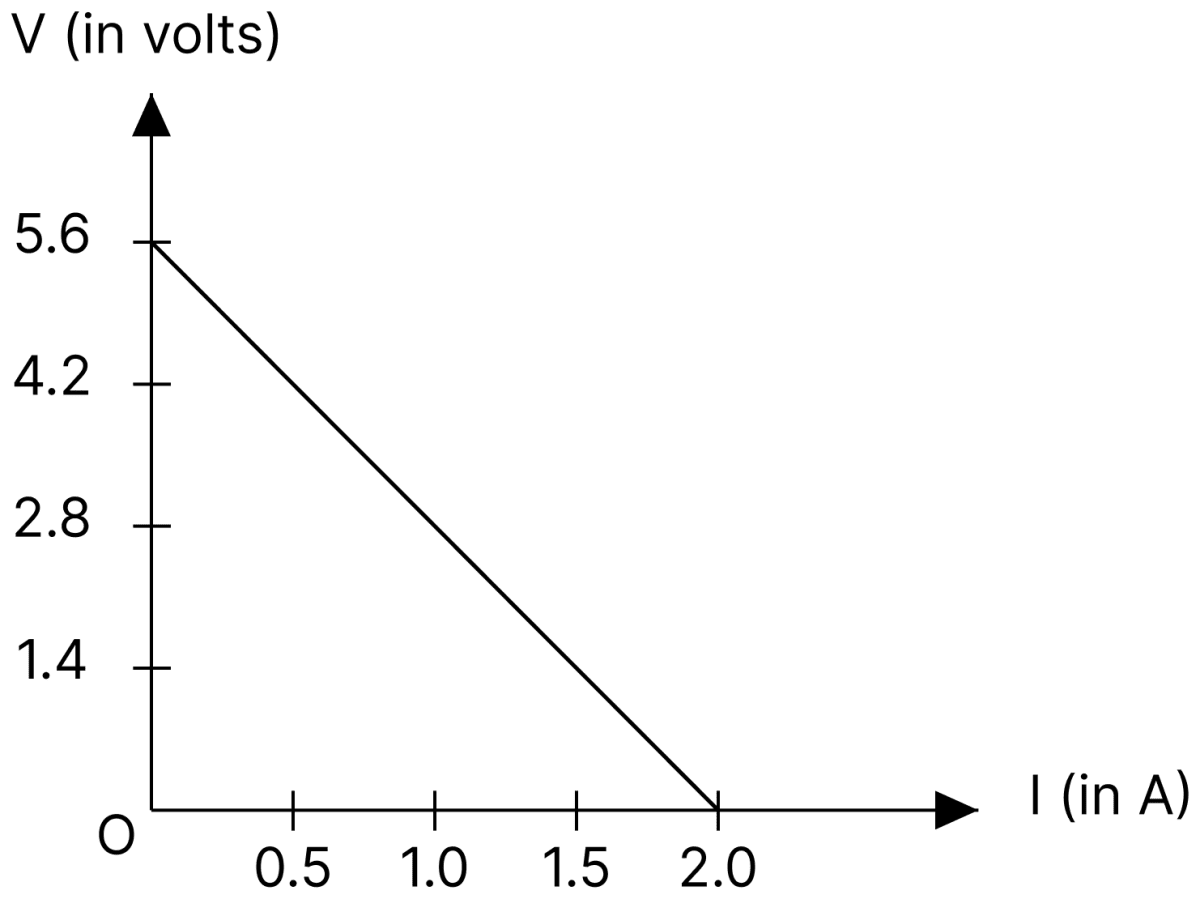
Four cells of identical emf E, internal resistance r, are connected in series to a variable resistor. The following graph shows the variation of terminal voltage of the combination with the current output :
(i) What is the emf of each cell used?
(ii) For what current from the cells, does maximum power dissipation occur in the circuit?
(iii) Calculate the internal resistance of each cell.
Answer
Given,
- Number of cells in series, n = 4
- From the graph, the intercept on the V-axis = 5.6 V and V = 0 at I = 2.0 A
(i) Emf of each cell : The intercept of the V–I graph on the V-axis gives the net emf of the combination, so 4E = 5.6 V.
(ii) Current for maximum power dissipation : When V = 0 the combination is short-circuited, so its total internal resistance is
The power dissipated in the external resistance is maximum when the external resistance equals the total internal resistance, that is, when R = 4r = 2.8 Ω. The current is then
(iii) Internal resistance of each cell :
Hence, E = 1.4 V, the current for maximum power dissipation is 1 A, and r = 0.7 Ω.
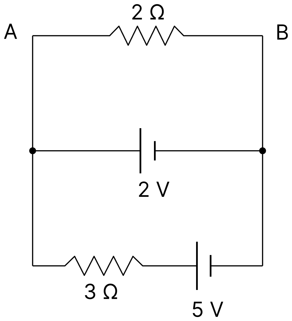
Determine current in 3 Ω resistance and potential difference between A and B in the given circuit diagram.
Answer
Given,
- The 2 Ω resistor, the 2 V cell and the branch containing the 3 Ω resistor with the 5 V cell are all connected between the same two points A and B
The middle branch contains only the 2 V cell, whose internal resistance is not given and is therefore taken as negligible. Its positive terminal is towards A, so
Let I be the current in the 3 Ω resistor, flowing from right to left. Applying Kirchhoff's loop law () to the loop formed by the lower branch and the 2 V cell,
Hence, the current in the 3 Ω resistance is 1 A, flowing from right to left, and the potential difference between A and B is 2 V.
A cell of emf E1 = 2V and internal resistance r1 = 1Ω is connected to another cell of emf E2 = 8V and internal resistance r2 = 2Ω through an external resistance of 4Ω as shown in the figure. Find the potential difference between point A and point C.
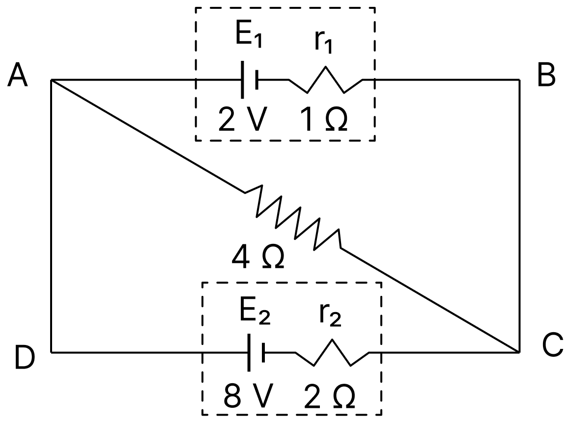
Answer
Given,
- E1 = 2 V, r1 = 1 Ω
- E2 = 8 V, r2 = 2 Ω
- External resistance, R = 4 Ω
The two cells are connected in parallel between the same two points, so they may be replaced by a single equivalent cell of emf
and internal resistance
The current through the 4 Ω resistor is
The potential difference between A and C is the potential drop across the 4 Ω resistor,
Hence, the potential difference between A and C is V.
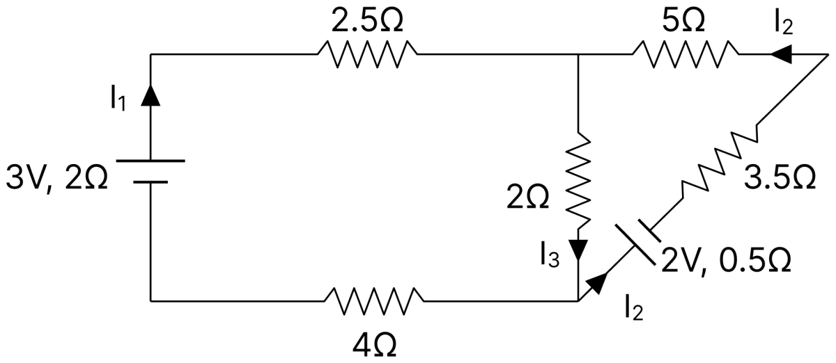
For the given electrical circuit, calculate the current through each branch using Kirchhoff's laws.
Answer
Given,
- Cell of 3 V with internal resistance 2 Ω in the left branch, carrying I1
- Cell of 2 V with internal resistance 0.5 Ω in the right branch, carrying I2
- Resistances 2.5 Ω and 4 Ω in the left loop, 5 Ω and 3.5 Ω in the right loop, and 2 Ω in the middle branch carrying I3
Junction rule : At the upper junction the currents I1 and I2 arrive and the current I3 leaves through the middle branch,
Loop rule for the left loop : Traversing the loop containing the 3 V cell, the 2.5 Ω, the 4 Ω and the middle 2 Ω resistors,
Loop rule for the right loop : Traversing the loop containing the 2 V cell, the 5 Ω, the 3.5 Ω and the middle 2 Ω resistors,
Substituting I3 = I1 + I2 from Eq. (i) into Eqs. (ii) and (iii),
Multiplying Eq. (iv) by 11 and Eq. (v) by 2 and subtracting,
From Eq. (v),
From Eq. (i),
Hence, I1 = 0.33 A, I2 = − 0.24 A and I3 = 0.09 A. The negative sign for I2 shows that this current actually flows opposite to the direction assumed.
Two cells of emfs 6 V and 12 V and internal resistances 1 Ω and 2 Ω respectively are connected in parallel so as to send current in the same direction through an external resistance of 15 Ω. Draw the circuit diagram. Using Kirchhoff's laws, calculate current through each branch of the circuit and PD across the 15 Ω resistance.
Answer
Given,
E1 = 6 V, r1 = 1 Ω
E2 = 12 V, r2 = 2 Ω
External resistance, R = 15 Ω
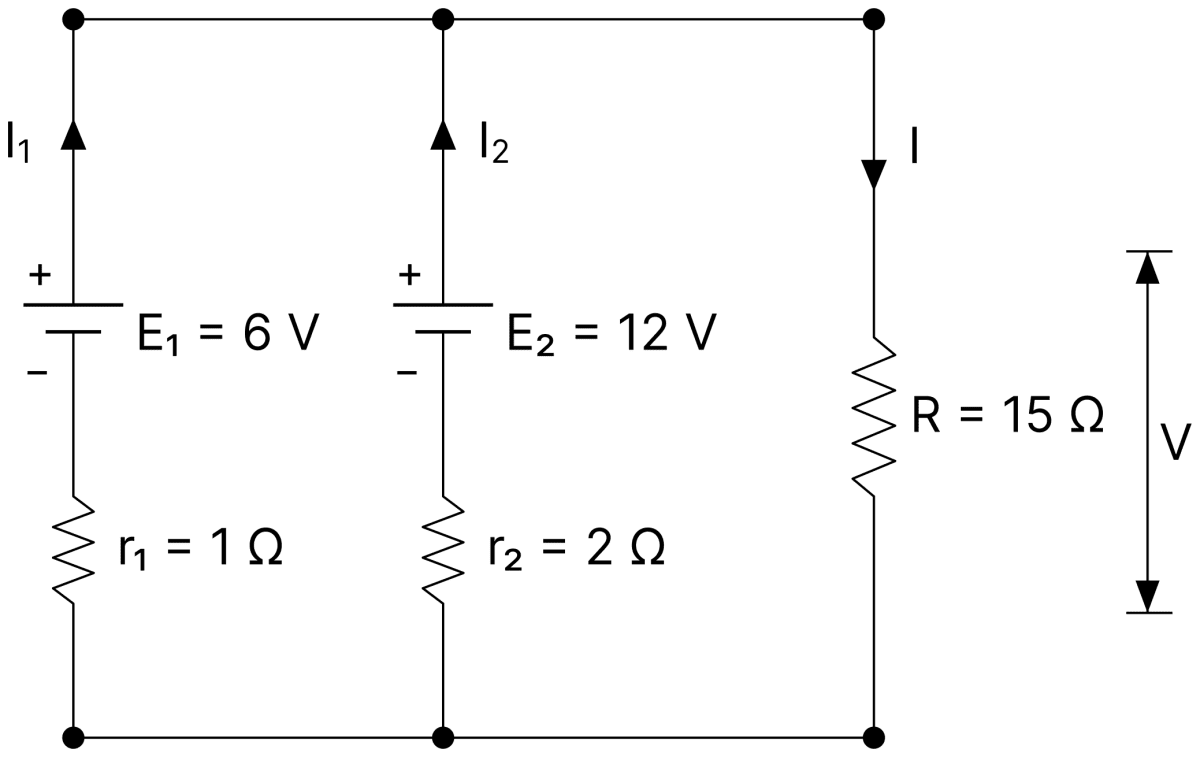
Let I1 be the current supplied by the 6 V cell, I2 be the current supplied by the 12 V cell, and I be the current through the 15 Ω resistance.
By Kirchhoff's junction law,
Applying Kirchhoff's loop law to the loop containing the 6 V cell,
Applying Kirchhoff's loop law to the loop containing the 12 V cell,
Substituting Eqs. (ii) and (iii) in Eq. (i),
Therefore, the potential difference across the 15 Ω resistance is
Current in the 6 V branch :
From Eq. (ii),
The negative sign shows that the actual current flows opposite to the assumed direction. Therefore, the current through the 6 V cell is
from its positive terminal to its negative terminal, i.e., the 6 V cell is being charged.
Current in the 12 V branch :
From Eq. (iii),
Hence, A flows through the 6 V cell in the charging direction, A flows through the 12 V cell in the discharging direction, A flows through the 15 Ω resistor, and the PD across it is 7.66 V.
Two cells A and B, each having emf 1.5 V and internal resistances 1.5 Ω and 0.5 Ω respectively, are joined in parallel with a 1.0 Ω resistor. Calculate currents drawn from the cells and their terminal PD's.
Answer
Given,
- E1 = E2 = 1.5 V
- r1 = 1.5 Ω, r2 = 0.5 Ω
- External resistance, R = 1.0 Ω
Since the two cells have equal emfs, the emf of the parallel combination is
and its internal resistance is
The total current in the external resistance is
The terminal potential difference of each cell is the potential drop across the 1.0 Ω resistor,
Current from cell A :
Current from cell B :
Hence, the currents drawn are A from A and A from B, and the terminal PD of each cell is V.
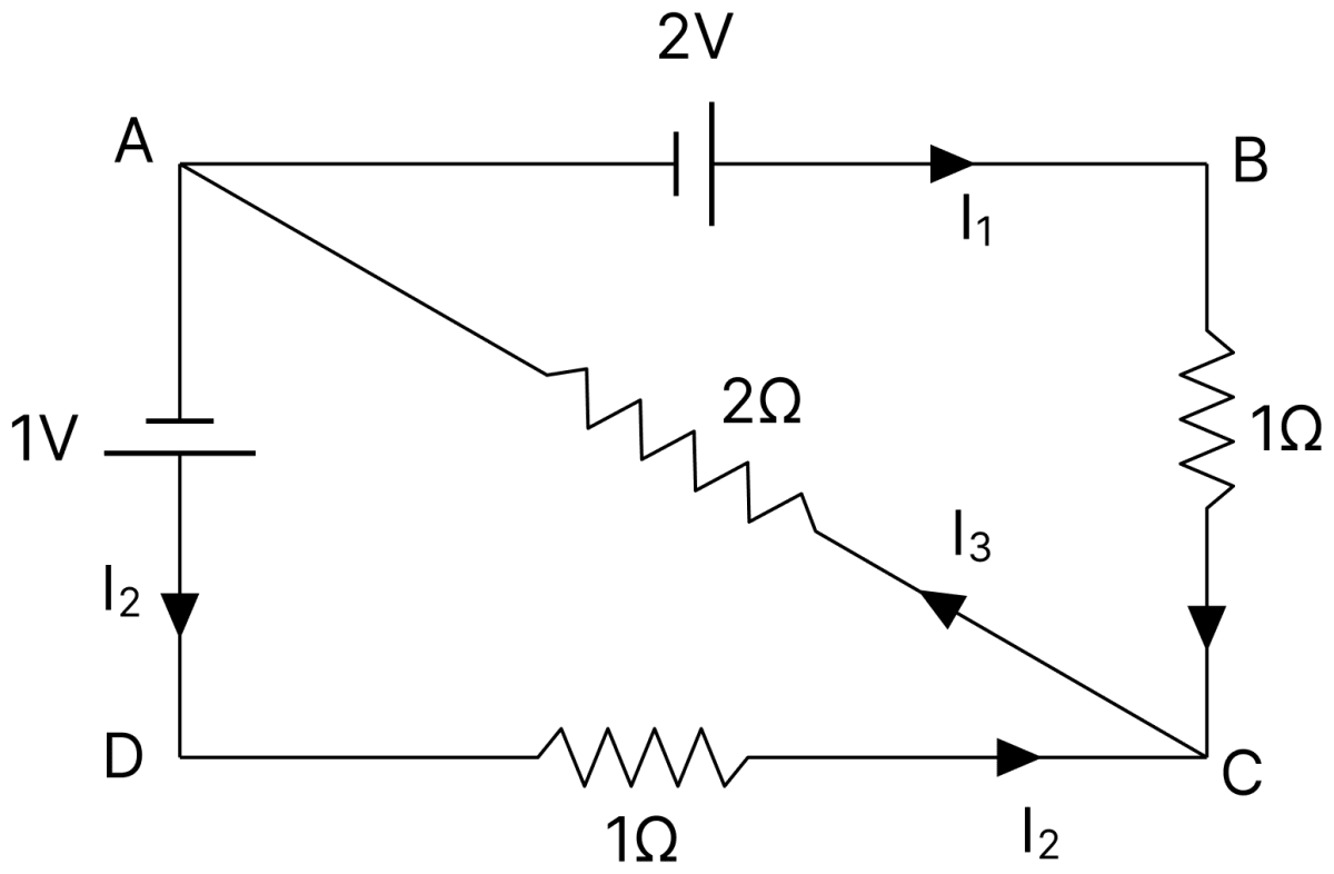
Calculate the currents I1, I2 and I3 in the given circuit. The cells have negligible internal resistances.
Answer
Given,
- Cells of 2 V and 1 V, both of negligible internal resistance
- Resistances 1 Ω (BC), 2 Ω (AC) and 1 Ω (DC)
Junction rule : At the junction A the current I3 arrives through the 2 Ω resistor and the currents I1 and I2 leave it,
Loop ABCA : The 2 V cell drives the current I1 through the 1 Ω resistor BC, and the loop is closed through the 2 Ω resistor carrying I3,
Loop ADCA : The 1 V cell drives the current I2 through the 1 Ω resistor DC,
Substituting Eq. (i) in Eqs. (ii) and (iii),
Multiplying Eq. (iv) by 3, Eq. (v) by 2 and subtracting,
From Eq. (v),
From Eq. (i),
Hence, I1 = 0.8 A, I2 = − 0.2 A and I3 = 0.6 A.
In the given circuit, assuming point A to be at zero potential, use Kirchhoff's rule to determine the potential at point B.
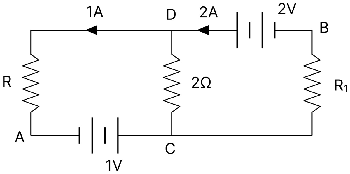
Answer
Given,
- VA = 0
- Currents of 1 A and 2 A as marked in the figure, a 2 Ω resistor in the branch DC, and cells of 1 V and 2 V
Junction rule at D : A current of 2 A arrives at D and a current of 1 A leaves it along the upper branch, so the current flowing from D to C through the 2 Ω resistor is
Potential at C : Going from A to C through the 1 V cell,
Potential at D : The current of 1 A flows from D to C through the 2 Ω resistor, so D is at the higher potential,
Potential at B : Going from B to D through the 2 V cell, the potential rises by 2 V,
Hence, the potential at point B is 1 V.
Using Kirchhoff's rules, determine the value of unknown resistance R in the circuit, so that no current flows through 4 Ω resistance. Also, find the potential difference between points A and D.
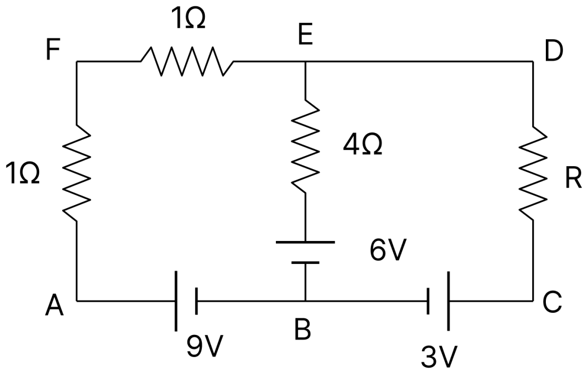
Answer
Given,
- Resistances 1 Ω (AF), 1 Ω (FE) and R (DC)
- Middle branch containing the 4 Ω resistor in series with a 6 V cell
- Cells of 9 V and 3 V in the lower branch
Since no current flows through the 4 Ω resistor, there is no potential drop across it, and the same current I flows round the outer loop AFEDCBA. The arm EB carries no current, so this loop may be traversed in two parts, AFEBA and EDCBE.
Value of R : Applying Kirchhoff's loop law () to the loop AFEBA,
Applying Kirchhoff's loop law to the loop EDCBE, in which the current I flows from D to C through R,
Potential difference between A and D : E and D are joined by a wire of no resistance, so VD = VE.
Hence, R = 2 Ω and VA − VD = 3 V.
In the experimental set up of metre bridge shown in the figure, the null point is obtained at a distance of 40 cm from A. If a 10 Ω resistor is connected in series with R1, the null point shifts by 10 cm.
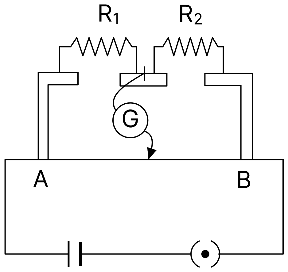
What resistance should be connected in parallel with (R1 + 10) Ω such that the null point shifts back to its initial position.
Answer
Given,
- Initial balancing length, l = 40 cm
- After connecting 10 Ω in series with R1, the resistance in the left gap increases, so the null point shifts 10 cm away from A, giving l' = 40 + 10 = 50 cm
For a metre bridge the condition of balance is
Initially,
After adding 10 Ω in series,
Substituting R1 = (2/3)R2 from Eq. (i) in Eq. (ii),
To bring the null point back to 40 cm, the resistance of the left gap must again become 20 Ω. Let X be connected in parallel with (R1 + 10) = 30 Ω,
Hence, a resistance of 60 Ω should be connected in parallel.
The given circuit diagram represents balanced Wheatstone's bridge, calculate R.
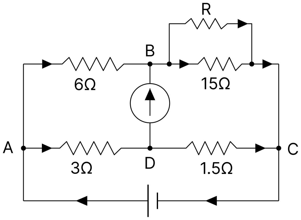
Answer
Given,
- Arms of the bridge : 6 Ω and the parallel combination of 15 Ω and R in the upper branch, 3 Ω and 1.5 Ω in the lower branch
Let S be the equivalent resistance of 15 Ω and R in parallel,
For the balanced Wheatstone bridge,
Therefore,
Hence, R = 3.75 Ω.
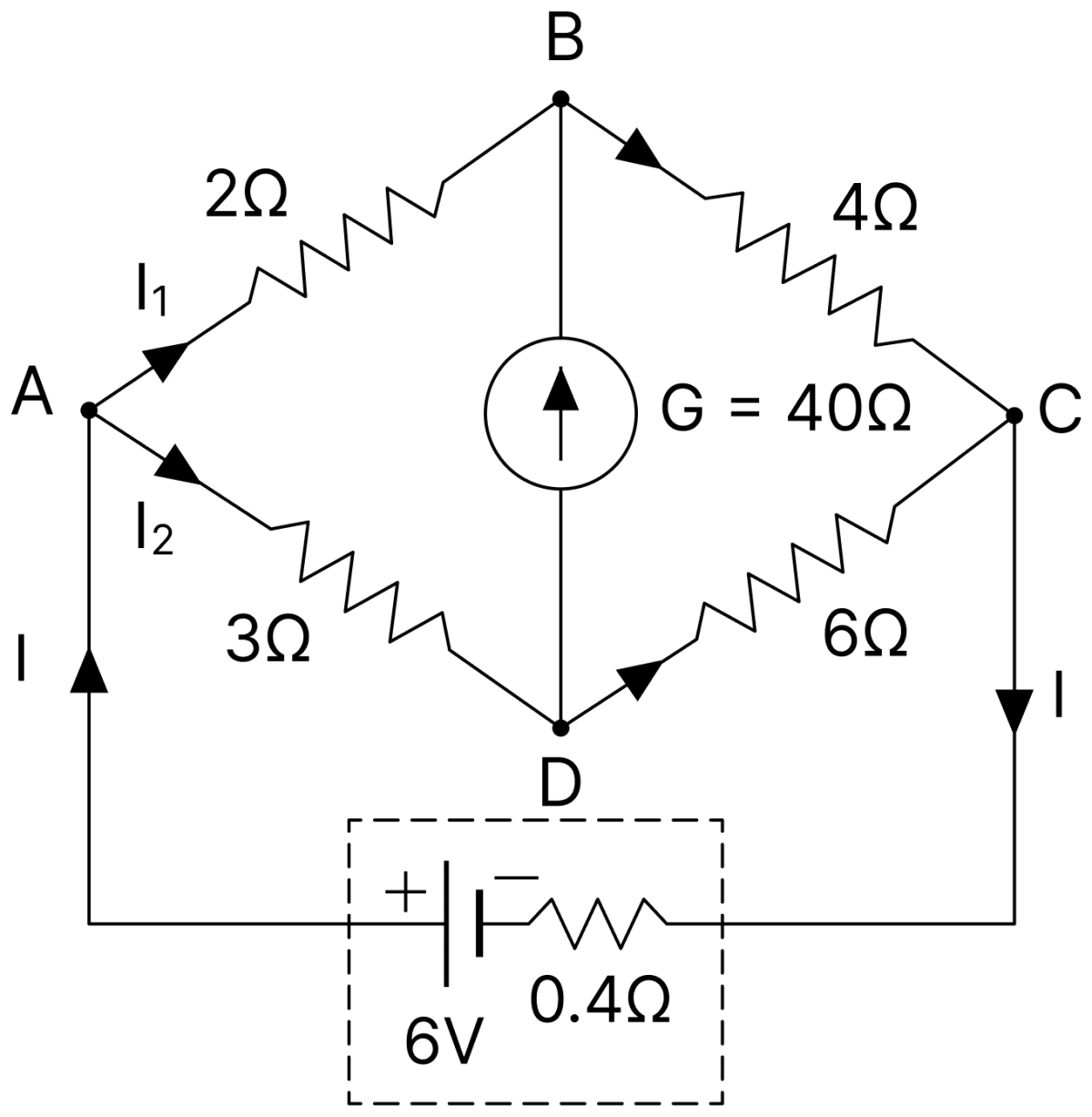
Calculate the currents I, I1 and I2 in the given Wheatstone's network of resistors. The internal resistance of the 6 V battery is 0.4 Ω.
Answer
Given,
- Arms of the bridge : 2 Ω and 4 Ω in the upper branch, 3 Ω and 6 Ω in the lower branch
- Galvanometer of 40 Ω across the bridge arm
- Emf of the battery, E = 6 V
- Internal resistance of the battery, r = 0.4 Ω
Test of balance :
Since,
The Wheatstone bridge is balanced. Therefore, no current flows through the galvanometer, and the galvanometer branch may be omitted.
The resistance of the upper branch is
The resistance of the lower branch is
These two branches are connected in parallel. Therefore, their equivalent resistance is
Including the internal resistance of the battery, the total resistance of the circuit is
Therefore, the total current supplied by the battery is
The potential difference across the parallel combination of the two branches is
Since both branches are in parallel, the potential difference across each branch is 5.4 V.
Current in the upper branch :
Using Ohm's law,
Current in the lower branch :
Using Ohm's law,
Also,
Hence, I = 1.5 A, I1 = 0.9 A and I2 = 0.6 A.
The given Wheatstone's bridge is almost balanced and the point C is earthed.
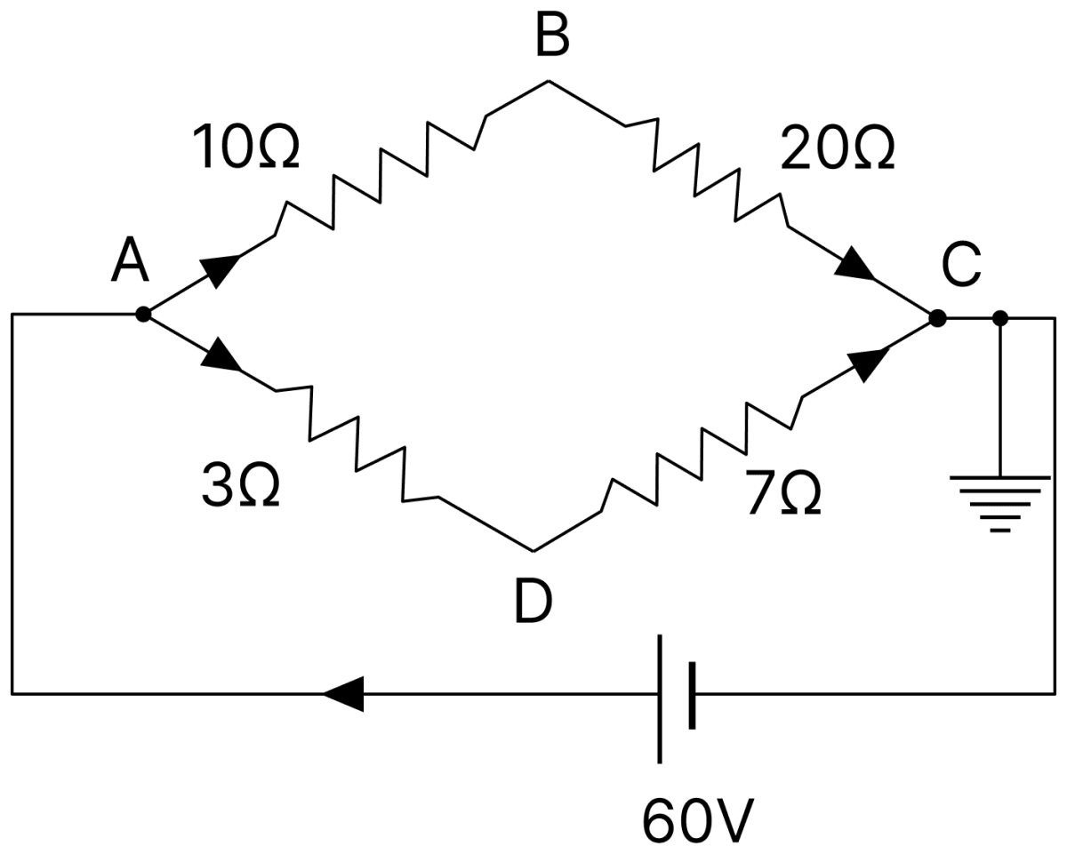
(a) Find the potentials at points B and D. (b) If a galvanometer be connected across BD, what will be the direction of current in it? (c) For what value of the resistor DC would the bridge be balanced?
Answer
Given,
- AB = 10 Ω, BC = 20 Ω, AD = 3 Ω, DC = 7 Ω
- Emf of the cell = 60 V, and VC = 0
Currents in the two branches : The branch ABC has resistance 10 + 20 = 30 Ω and the branch ADC has resistance 3 + 7 = 10 Ω, and both are connected across the 60 V cell.
(a) Potentials at B and D : Since C is earthed, VC = 0.
(b) Since VD > VB, the current in the galvanometer would flow from D to B.
(c) Value of DC for balance : For the balanced bridge,
Hence, VB = + 40 V, VD = + 42 V, the current would flow from D to B, and DC should be 6 Ω.
In determining the resistance of a given wire with the help of metre bridge, the null-point is obtained at a distance of 40 cm on taking out 2 Ω resistance from the resistance box. What is the resistance of the wire? To obtain the null-point at a distance of 60 cm, how much resistance in ohm, will have to be taken out from the resistance box?
Answer
Given,
- R = 2 Ω, balancing length l = 40 cm
- Required balancing length in the second case, l' = 60 cm
Taking the resistance box (R) in the left gap and the wire (S) in the right gap, with the balancing length l measured from the left end, the condition of balance of the metre bridge is
Resistance of the wire :
Resistance for a null-point at 60 cm :
Hence, the resistance of the wire is 3 Ω, and 4.5 Ω will have to be taken out from the resistance box.
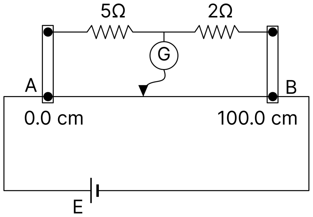
In metre bridge set up, uniform wire AB is of 100.0 cm length. Copper strips are of negligible resistance. When 5Ω is shunted by a wire, the balance point is found to be at 62.5 cm from A. Find the resistance of the shunt.
Answer
Given,
- Resistance in the left gap = 5 Ω shunted by a wire of resistance X
- Resistance in the right gap = 2 Ω
- Balancing length, l = 62.5 cm
The resistance of the left gap is the parallel combination of 5 Ω and X,
Applying the balance condition of the metre bridge,
Therefore,
Hence, the resistance of the shunt is 10 Ω.
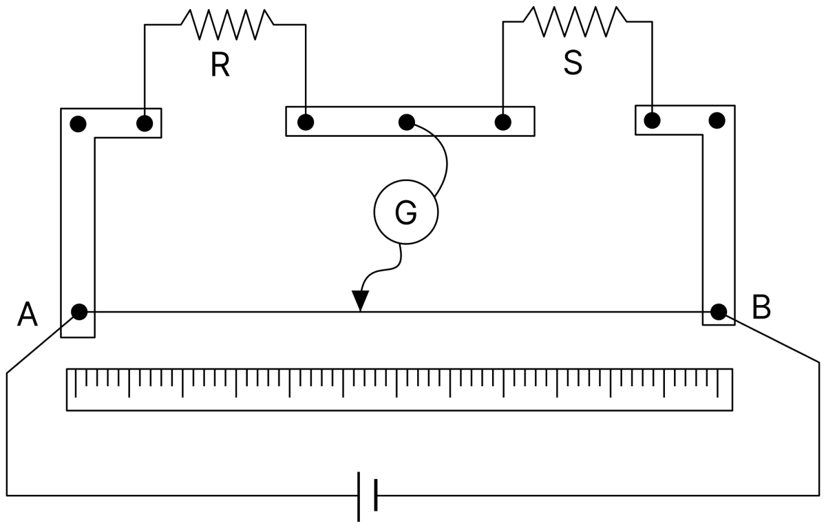
In a metre bridge, the null point is found at a distance of 60.0 cm from A. If now a resistance of 5Ω is connected in series with S, the null point occurs at 50 cm. Determine the values of R and S.
Answer
Given,
- Initial balancing length, l = 60.0 cm
- Balancing length after adding 5 Ω in series with S, l' = 50 cm
Initially,
After adding 5 Ω in series with S,
From Eqs. (i) and (ii),
Hence, R = 15 Ω and S = 10 Ω.
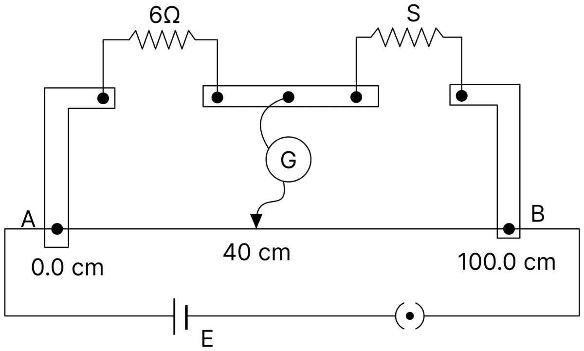
In a metre bridge circuit, resistance in the left hand gap is 6 Ω and an unknown resistance S is in the right hand gap as shown in the figure. The null point is found to be at 40 cm from the left end of the wire. What resistance should be connected to S so that the new null point is obtained just in the middle of the wire AB?
Answer
Given,
- Resistance in the left gap, R = 6 Ω
- Balancing length, l = 40 cm
- Required balancing length, l' = 50 cm
Value of S :
For the null point at the middle of the wire, l' = 50 cm, so the resistance S' of the right gap must be
Since the required resistance is less than S, a resistance X must be joined in parallel with S,
Hence, a resistance of 18 Ω should be connected in parallel with S.
A 3 V battery of internal resistance 1 Ω is joined to a sliding wire of length 100 cm and resistance 5 Ω. A voltmeter, which takes negligible current, is connected across 60 cm length of the wire. (a) What is the reading of the voltmeter? (b) If the resistance of the voltmeter were 150 Ω, then what would have been its reading?
Answer
Given,
- E = 3 V, r = 1 Ω
- Length of the wire = 100 cm, resistance of the wire = 5 Ω
- Voltmeter connected across 60 cm of the wire
The resistance of 60 cm of the wire is
and that of the remaining 40 cm is 2 Ω.
(a) Voltmeter taking negligible current : The whole wire carries the same current,
(b) Voltmeter of resistance 150 Ω : The voltmeter is in parallel with the 3 Ω portion,
The total resistance of the circuit is
Hence, the readings are (a) 1.5 V and (b) 1.485 V.
A 10 m long potentiometer wire has a potential gradient of 0.0025 V/cm along its length. Calculate the length of the wire at which null-point is obtained for a 1.025 V standard cell. Also, find the emf of another cell for which the null-point is obtained at 860 cm length. What maximum PD can be measured by this potentiometer?
Answer
Given,
- Length of the wire, L = 10 m = 1000 cm
- Potential gradient, K = 0.0025 V/cm
- Emf of the standard cell, E1 = 1.025 V
- Balancing length for the second cell, l2 = 860 cm
Balancing length for the standard cell :
Emf of the second cell :
Maximum PD that can be measured : This corresponds to the whole length of the wire,
Hence, the null-point is at 410 cm, the emf of the other cell is 2.15 V and the maximum PD that can be measured is 2.5 V.
A potentiometer is being used to compare two resistances. The balancing length for a standard resistor R = 10.0 Ω is 58.3 cm, while that for an unknown resistance X is 68.5 cm. Determine the value of X. What would you do if you failed to find a null-point on the potentiometer wire AB?
Answer
Given,
- R = 10.0 Ω, l1 = 58.3 cm
- l2 = 68.5 cm
The same current flows through both the resistors, so the potential difference across each is proportional to its resistance, and the balancing length is proportional to the potential difference. Hence
If no null-point is obtained, it means that the potential drop across R or X is greater than the potential difference across the whole wire AB. The current must then be reduced, and hence the potential drop, by putting a suitable resistor in series with R and X.
Hence, X = 11.75 Ω.
A cell gives a balance with 85 cm of a potentiometer wire. When the terminals of the cell are shorted through a resistance of 7.5 Ω a balance is obtained at 75 cm. Find the internal resistance of the cell.
Answer
Given,
- l1 = 85 cm, l2 = 75 cm
- Shunt resistance, R = 7.5 Ω
Hence, the internal resistance of the cell is 1.0 Ω.
A cell of emf 1.25 V gives a balance point at 35.0 cm length of a potentiometer wire. For an other cell, the balance point shifts to 63.0 cm. What is the emf of the second cell?
Answer
Given,
- E1 = 1.25 V, l1 = 35.0 cm
- l2 = 63.0 cm
Since the emf is proportional to the balancing length,
Hence, the emf of the second cell is 2.25 V.
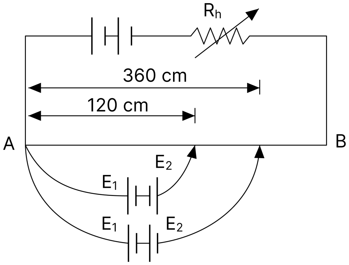
Figure shows a long potentiometer wire AB having a constant potential gradient. The null points for the two primary cells of emfs E1 and E2 connected in the manner shown are obtained at a distance of l1 = 120 cm and l2 = 360 cm from the end A. Determine (i) E1/E2 and (ii) position of null point for the cell E1 only. (Assume E1 > E2)
Answer
Given,
- l1 = 120 cm, when the two cells oppose each other
- l2 = 360 cm, when the two cells support each other
Since the balancing length is proportional to the net emf in the secondary circuit,
(i) Ratio of the emfs : Adding Eqs. (i) and (ii),
Subtracting Eq. (i) from Eq. (ii),
(ii) Null point for E1 alone :
Hence, E1/E2 = 2 and the null point for E1 alone is at 240 cm from A.
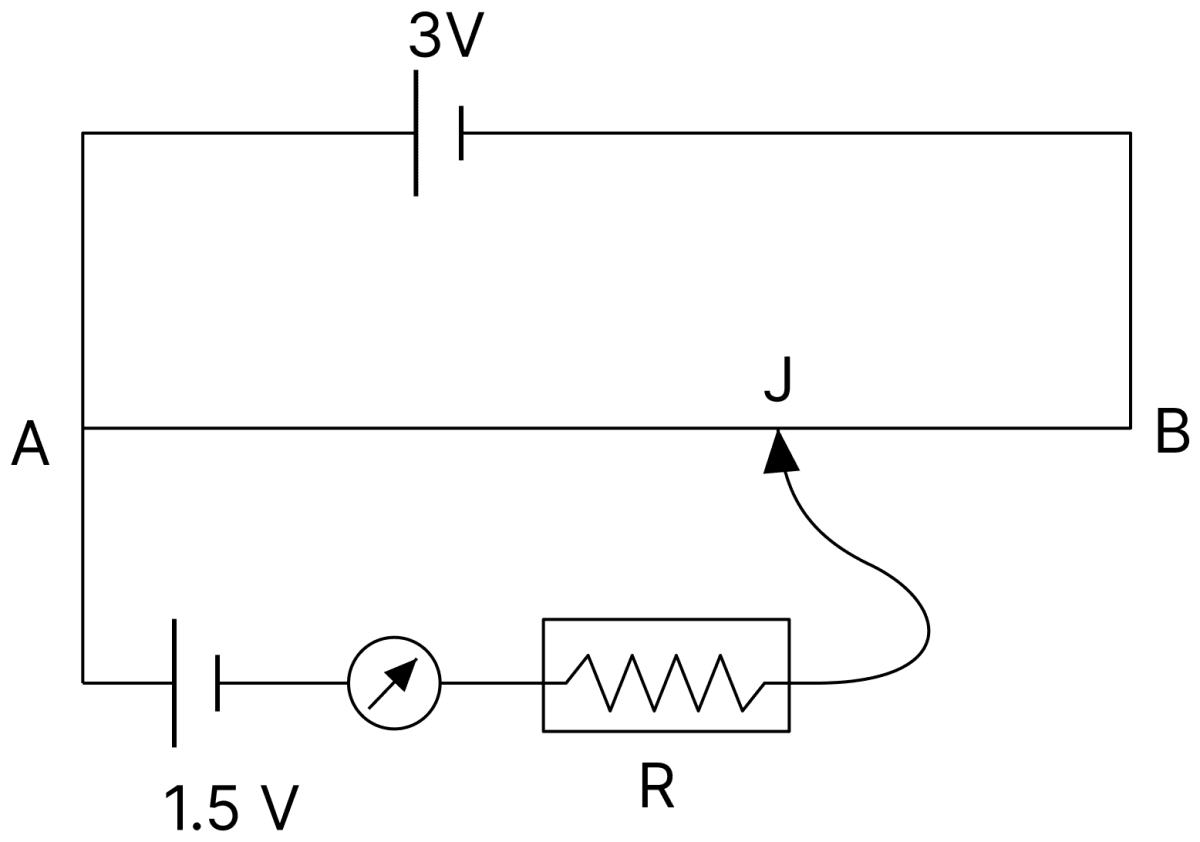
A potentiometer wire of length 1 m is connected to a driver cell of emf 3 V as shown in the figure. When a cell of emf 1.5 V is used in the secondary circuit, the balance point is found to be 60 cm. On replacing this cell by a cell of unknown emf, the balance point shifts to 80 cm.
(i) Calculate unknown emf of the cell.
(ii) Explain with reason, whether the circuit works if the driver cell is replaced with a cell of emf 1 V.
(iii) Does the high resistance R, used in the secondary circuit affect the balance point? Justify your answer.
Answer
Given,
- E1 = 1.5 V, l1 = 60 cm
- l2 = 80 cm
(i) Unknown emf :
(ii) The circuit will not work if the driver cell is of emf 1 V, because the total potential difference across the wire AB would then be only 1 V, which cannot balance the 1.5 V of the cell in the secondary circuit. No balance point could be obtained anywhere on the wire.
(iii) No, the high resistance R does not affect the balance point. At the balance point no current flows through the galvanometer, so the cell in the secondary circuit remains in an open circuit and there is no potential drop across R.
Hence, the unknown emf is 2.0 V.
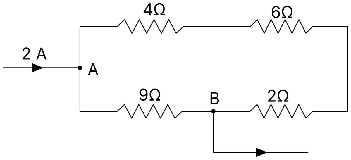
Calculate in the given combination of four resistors : (i) equivalent resistance between points A and B, (ii) PD between A and B, (iii) currents in the various resistors.
Answer
Given,
- Current entering at A, I = 2 A
- The 9 Ω resistor joins A directly to B, while the 4 Ω, 6 Ω and 2 Ω resistors form the other path from A to B
(i) Equivalent resistance : The upper path contains 4 Ω, 6 Ω and 2 Ω in series,
This is in parallel with the 9 Ω resistor,
(ii) PD between A and B :
(iii) Currents in the resistors :
Current in the 9 Ω resistor,
Current in the 12 Ω path, that is, in the 4 Ω, 6 Ω and 2 Ω resistors,
Hence, R = Ω, V = V, the current in the 9 Ω resistor is A and that in the 4 Ω, 6 Ω and 2 Ω resistors is A.
What the ammeter A will read when (a) the key K is off, (b) the key K is on? The resistance of the ammeter is negligible.
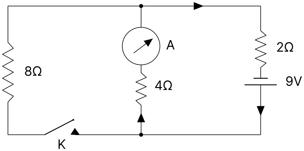
Answer
Given,
- Emf of the cell = 9 V with a 2 Ω resistor in series
- 4 Ω resistor in the branch containing the ammeter, and 8 Ω resistor in the branch containing the key K
(a) When the key K is off : The 8 Ω branch is broken, so the current flows only through the 2 Ω and the 4 Ω resistors in series,
(b) When the key K is on : The 8 Ω resistor comes in parallel with the 4 Ω resistor,
The total resistance of the circuit is
The ammeter carries the current in the 4 Ω branch,
Hence, the ammeter reads 1.5 A when K is off and A when K is on.
In steady state calculate the energy stored in the capacitor included in the given circuit.
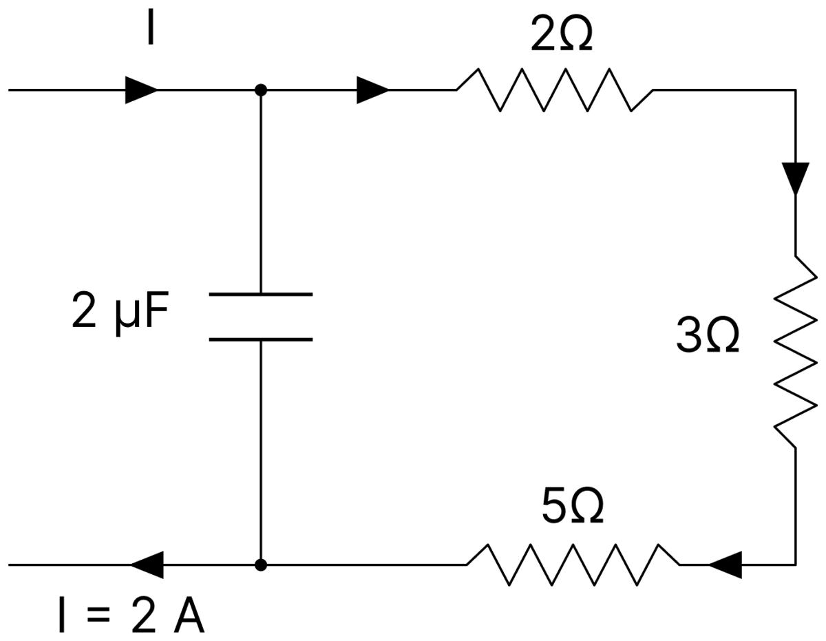
Answer
Given,
- Capacitance, C = 2 µF = 2 × 10⁻⁶ F
- Current in the circuit, I = 2 A
- Resistances 2 Ω, 3 Ω and 5 Ω in series in the loop
In the steady state no current flows through the branch containing the capacitor, so the whole current of 2 A flows through the 2 Ω, 3 Ω and 5 Ω resistors in series. The potential difference across the plates of the capacitor is therefore equal to the potential drop across these three resistors,
The energy stored in the capacitor is
Hence, the energy stored in the capacitor is 4 × 10⁻⁴ J.
Compute the reading of the ammeter A in the given network of resistors.
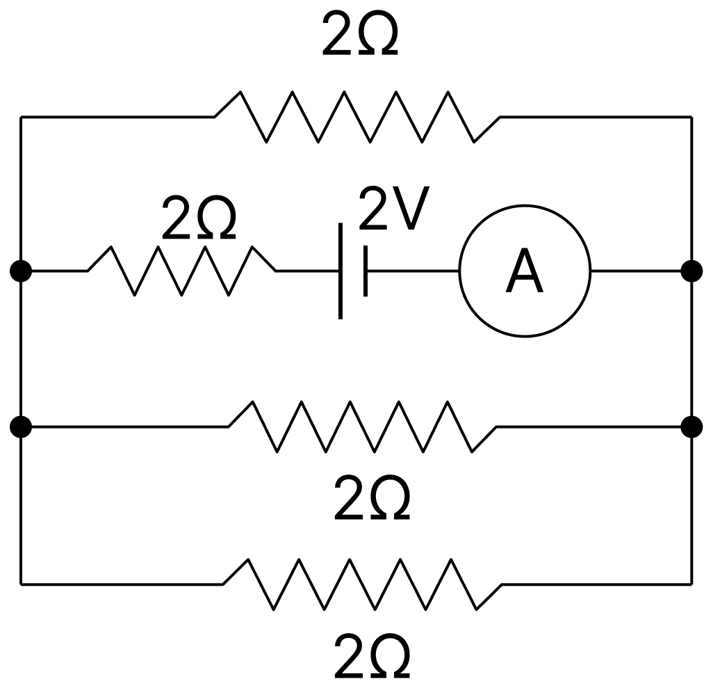
Answer
Given,
- Emf of the cell = 2 V, in series with a 2 Ω resistor and the ammeter in one branch
- Three other branches, each of 2 Ω, connected between the same two points
The three 2 Ω resistors are in parallel,
This combination is in series with the 2 Ω resistor of the branch containing the cell,
The ammeter reads the current drawn from the cell,
Hence, the ammeter reads 0.75 A.
In the given diagram, calculate the resistance of the voltmeter. The ammeter reading is 2 A, the voltmeter reading is 120 V and R is 75 Ω.
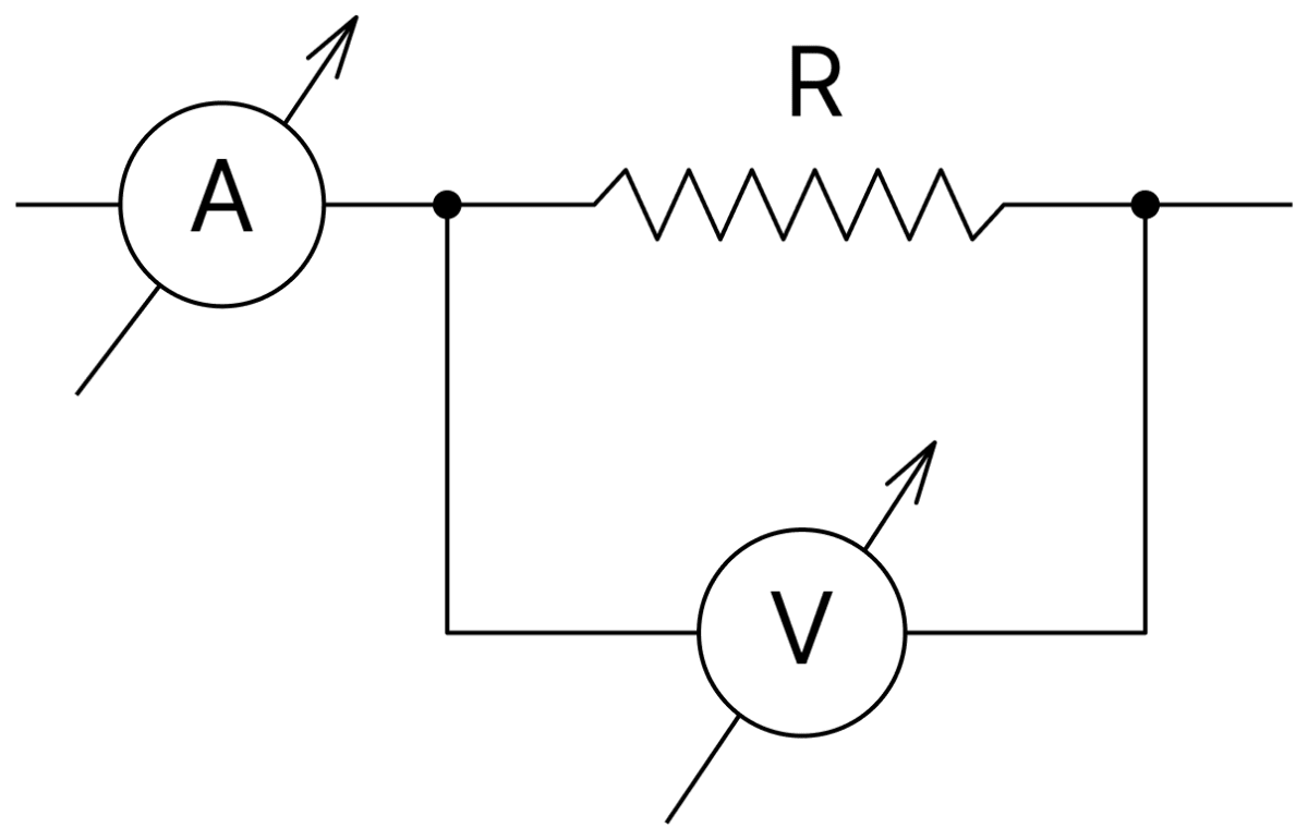
Answer
Given,
- Ammeter reading, I = 2 A
- Voltmeter reading, V = 120 V
- R = 75 Ω
The voltmeter is connected across R, so both have the same potential difference of 120 V.
Current through R,
The ammeter reads the total current, so the current through the voltmeter is
The resistance of the voltmeter is
Hence, the resistance of the voltmeter is 300 Ω.
An experiment was set up with the circuit diagram shown in the figure. Given that R1 = 10Ω, R2 = R3 = 5Ω, r = 0 Ω and E = 5V.
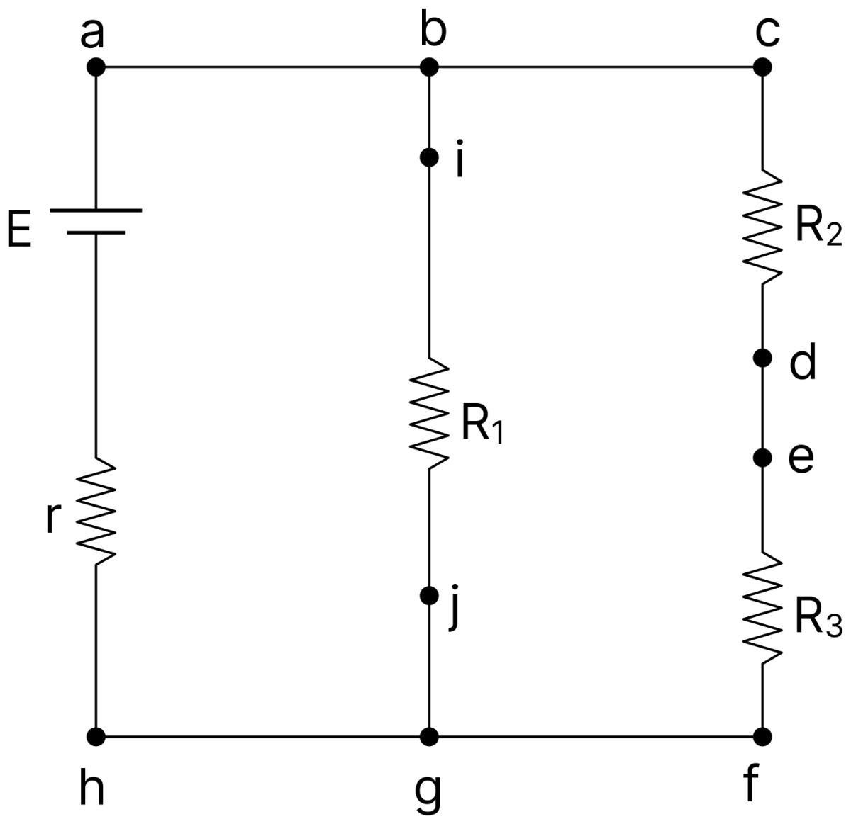
(i) The points with the same potential are :
(a) b, c, d
(b) f, h, j
(c) d, e, f
(d) a, b, j
(ii) The current through branch bg is :
(a) 1A
(b) A
(c) A
(d) A
(iii) The power dissipated in R1 is :
(a) 2 W
(b) 2.5 W
(c) 3 W
(d) 4.5 W
(iv) The potential difference across R3 is :
(a) 1.5 V
(b) 2 V
(c) 2.5 V
(d) 3V
Answer
Given,
- R1 = 10 Ω, R2 = R3 = 5 Ω
- E = 5 V, r = 0
(i) f, h, j
The lower wire h–g–f contains no resistance, so all the points on it are at the same potential. The point j lies at the lower end of R1 and is joined to g by a plain wire, so j is also at this same potential.
(ii) A
Since the internal resistance of the cell is zero, the whole emf appears across R1, which is connected between the upper and the lower wires,
(iii) 2.5 W
(iv) 2.5 V
R2 and R3 are joined in series across the same 5 V, and they are equal, so the potential difference is shared equally between them,
A standard cell of emf 1.08 V is balanced by the potential difference across 91 cm of a 1 m long wire supplied by a cell of emf 2 V through a series resistor of resistance 2 Ω. The internal resistance of the cell is zero. Find the resistance per unit length of the potentiometer wire.
Answer
Given,
- Emf of the standard cell, E = 1.08 V
- Balancing length, l = 91 cm = 0.91 m
- Emf of the driving cell = 2 V, internal resistance = 0
- Series resistance = 2 Ω
- Length of the potentiometer wire, L = 1 m
Let R be the resistance of the whole potentiometer wire. The current in the primary circuit is
The resistance of 91 cm of the wire is 0.91 R, so the potential difference across this length is
At the balance point this equals the emf of the standard cell,
Since the wire is 1 m long, the resistance per unit length is
Hence, the resistance per unit length of the potentiometer wire is 2.92 Ω/m.