
A 2V battery with internal resistance of 0.1Ω is charged with a current of 5A. Calculate the potential difference between the terminals of the battery.
Answer
Given,
- E = 2 V, r = 0.1 Ω
- Charging current, I = 5 A
During charging the current is sent into the battery from outside, so
Hence, the potential difference between the terminals of the battery is 2.5 V.
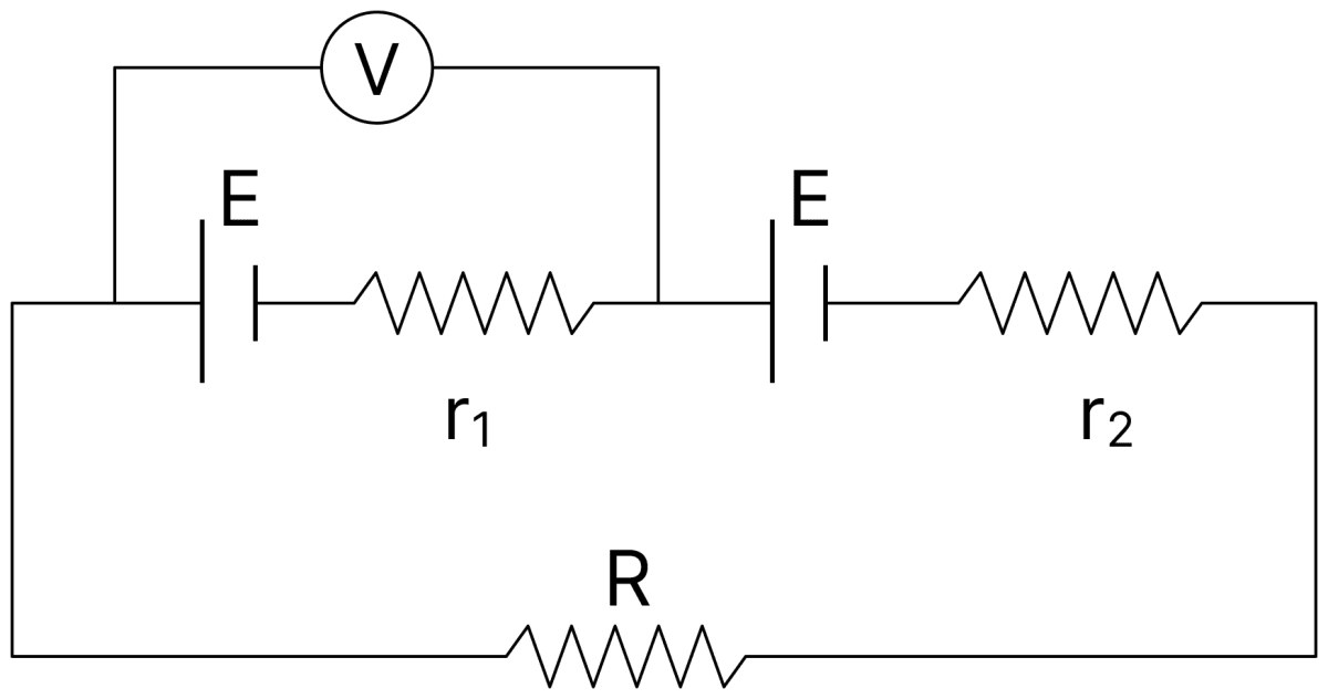
Two cells of same emf E, but different internal resistances r1 and r2 are connected to an external resistance R as shown in the figure. The voltmeter V reads zero. Obtain an expression for R in terms of r1 and r2. Calculate the voltage across the cell of internal resistance r2. (Assume that the voltmeter V is of infinite resistance).
Answer
Given,
- Emf of each cell = E
- Internal resistances r1 and r2
- Voltmeter connected across the first cell reads zero
The two cells are joined in series, so the current in the circuit is
Expression for R : The voltmeter reads the terminal potential difference of the first cell, and this is zero,
Equating the two expressions for I,
Voltage across the cell of internal resistance r2 :
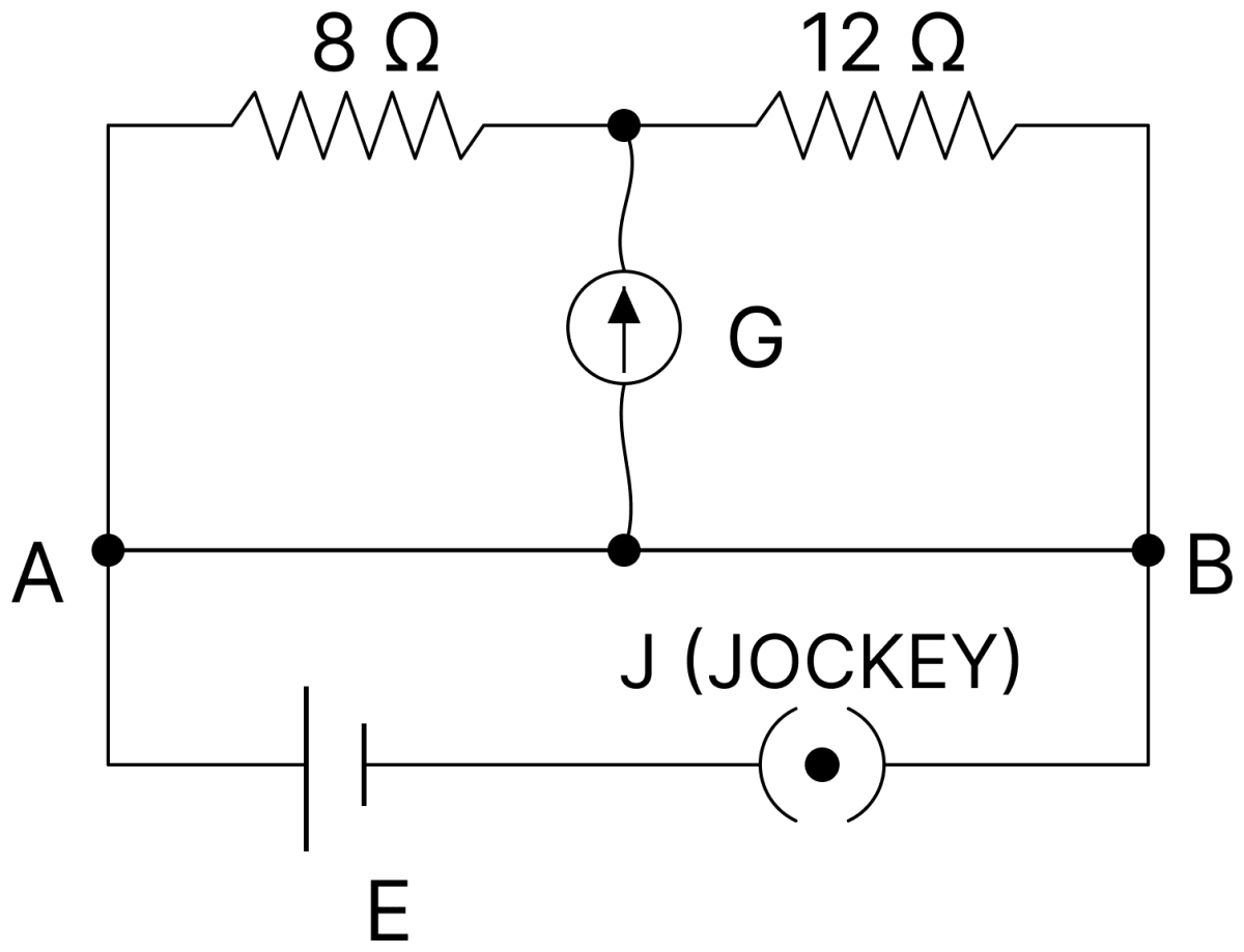
In the circuit (figure given) the length of the wire AB = 400 cm. Where should the jockey J be placed, so that the galvanometer shows a zero deflection?
Answer
Given,
- Resistances in the two upper arms = 8 Ω and 12 Ω
- Length of the wire AB = 400 cm
The wire AB forms the lower two arms of a Wheatstone bridge, and the resistance of a portion of a uniform wire is proportional to its length. Hence at zero deflection,
Hence, the jockey should be placed at 160 cm from the end A.
Why is a potentiometer preferred over a voltmeter in measuring the emf of a cell?
Answer
A voltmeter draws some current from the cell, so it measures the terminal potential difference and not the emf. In a potentiometer, at the balance point no current is drawn from the cell in the secondary circuit, so it measures the true emf of the cell.
Define the emf of a cell in terms of the work done in moving a charge through the cell. Using Joule's law obtain the equation, emf = I(R + r). (The symbols have their usual meaning)
Answer
Emf : If dW is the work done by the cell in forcing a charge dq from its negative to its positive electrode, then the emf of the cell is
Derivation : Let a cell of emf E and internal resistance r send a steady current I through an external resistance R. In time dt the charge that flows is dq = I dt, so the work done by the cell is
By Joule's law, the heat produced in time dt in the external resistance and in the internal resistance is
By the conservation of energy,
Dividing throughout by I dt,
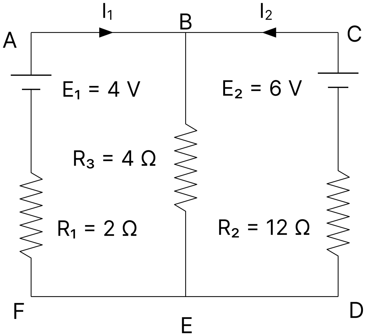
In the circuit given, E1 and E2 are two cells of emfs 4 V and 6V respectively, having negligible internal resistance. Applying Kirchhoff's laws of electrical networks, find the value of I1 and I2.
Answer
Given,
- E1 = 4 V, E2 = 6 V, internal resistances negligible
- R1 = 2 Ω, R2 = 12 Ω, R3 = 4 Ω
Junction rule : The currents I1 and I2 meet at the junction B and the current (I1 + I2) flows through R3.
Loop containing E1 and R3 :
Loop containing E2 and R3 :
Dividing Eq. (i) by 2 and Eq. (ii) by 2,
From Eq. (iii), I2 = 1 − 1.5 I1. Substituting in Eq. (iv),
Hence, I1 = 0.5 A and I2 = 0.25 A.
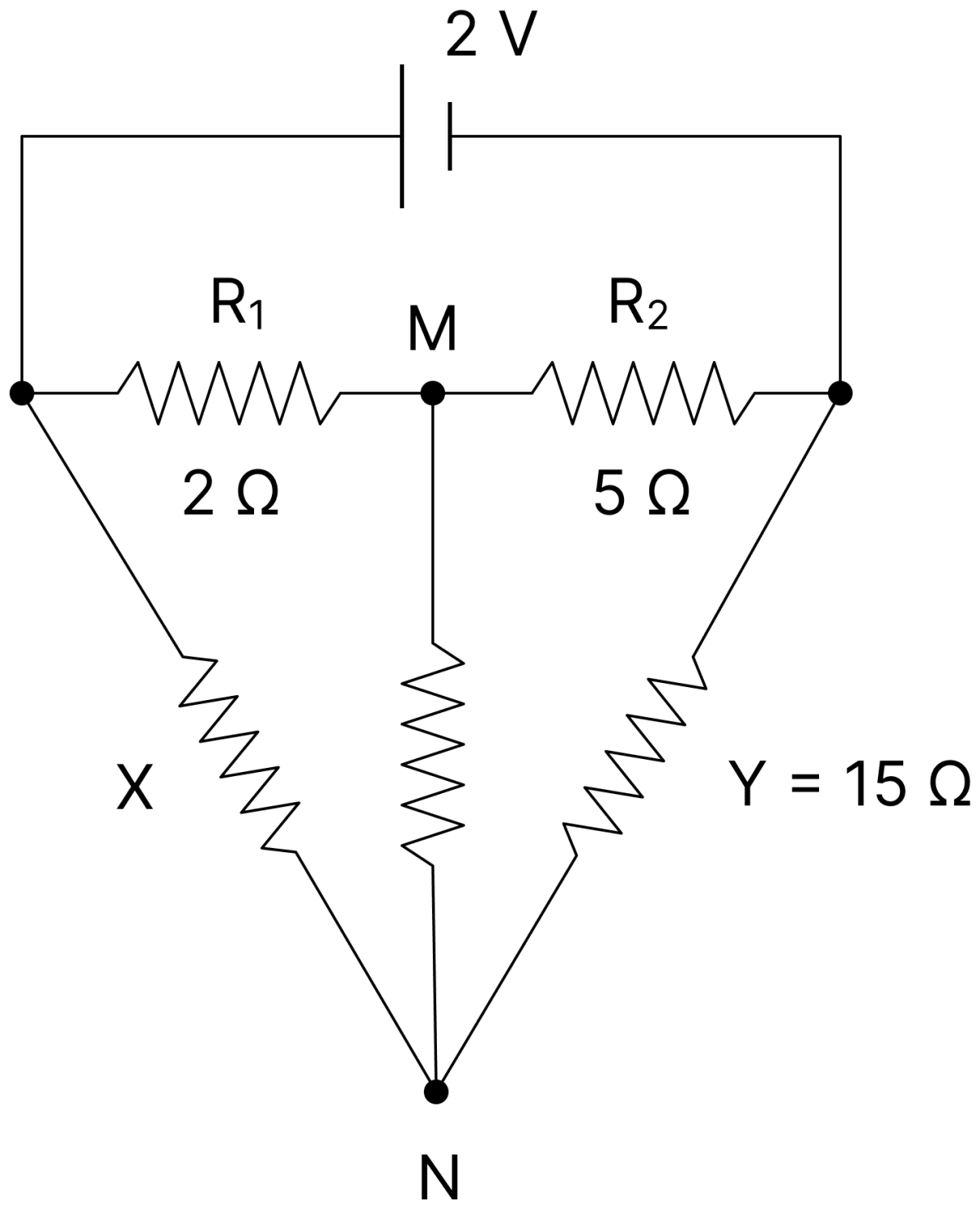
Find the value of resistance X in the circuit aside so that the junctions M and N are at the same potential.
Answer
Given,
- R1 = 2 Ω, R2 = 5 Ω, Y = 15 Ω
When M and N are at the same potential, no current flows between them and the network is a balanced Wheatstone bridge,
Hence, X = 6 Ω.
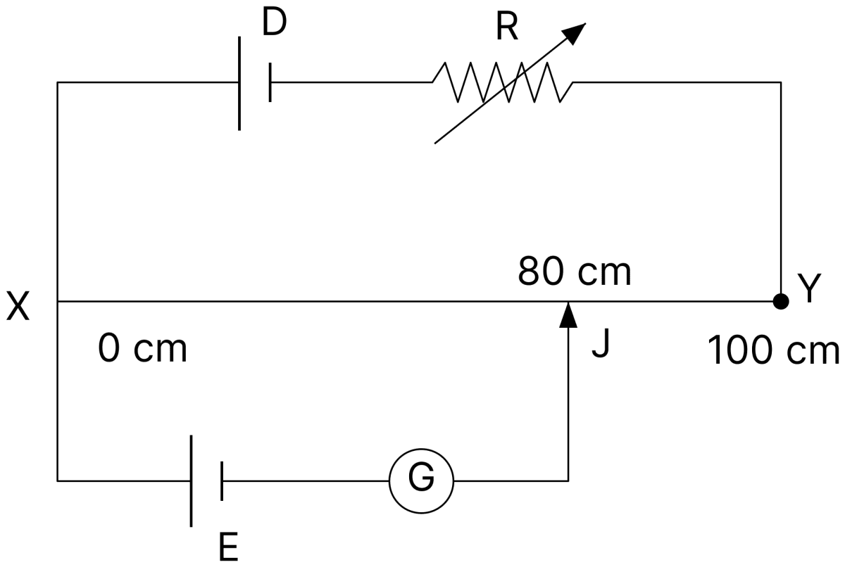
The given figure shows a uniform manganin wire XY of length 100 cm and resistance 9Ω, connected to an accumulator D of emf 4 V and internal resistance 1 Ω through a variable resistance R. E is a cell of emf 1.8 V connected to the wire XY via jockey J and a galvanometer G. It is found that the galvanometer shows no deflection when XJ = 80 cm. Find the value of R.
Answer
Given,
- Resistance of the wire XY = 9 Ω, length = 100 cm
- Emf of the accumulator = 4 V, internal resistance = 1 Ω
- Emf of the cell E = 1.8 V, balancing length XJ = 80 cm
The resistance of 80 cm of the wire is
At the balance point the potential difference across XJ equals the emf of the cell E,
The current in the primary circuit is
Hence, the value of R is 6 Ω.
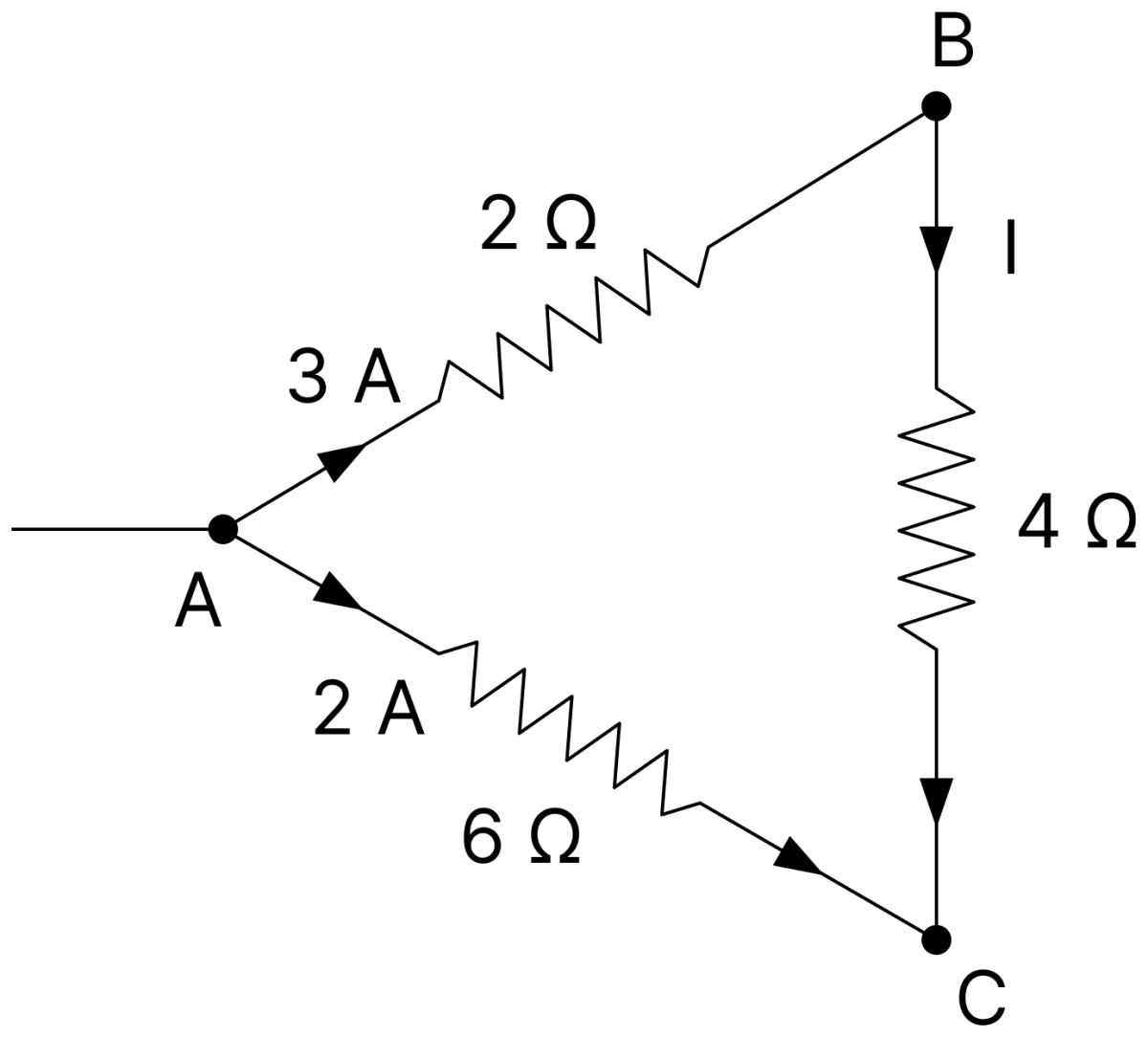
A part of an electric circuit is shown in figure. Using Kirchhoff's second law, find the current I flowing through the 4 Ω resistor.
Answer
Given,
- Current of 3 A through the 2 Ω resistor from A to B
- Current of 2 A through the 6 Ω resistor from A to C
- Current I through the 4 Ω resistor from B to C
Applying Kirchhoff's second law to the closed loop ABCA,
Hence, the current flowing through the 4 Ω resistor is 1.5 A.
In the circuit shown in figure, PQ is a uniform metallic wire of length 4 m and resistance 20 Ω. Battery B has an emf of 10 V and internal resistance of 1 Ω. J is a jockey or slide contact. Resistance of the ammeter A and connecting wires is negligible.
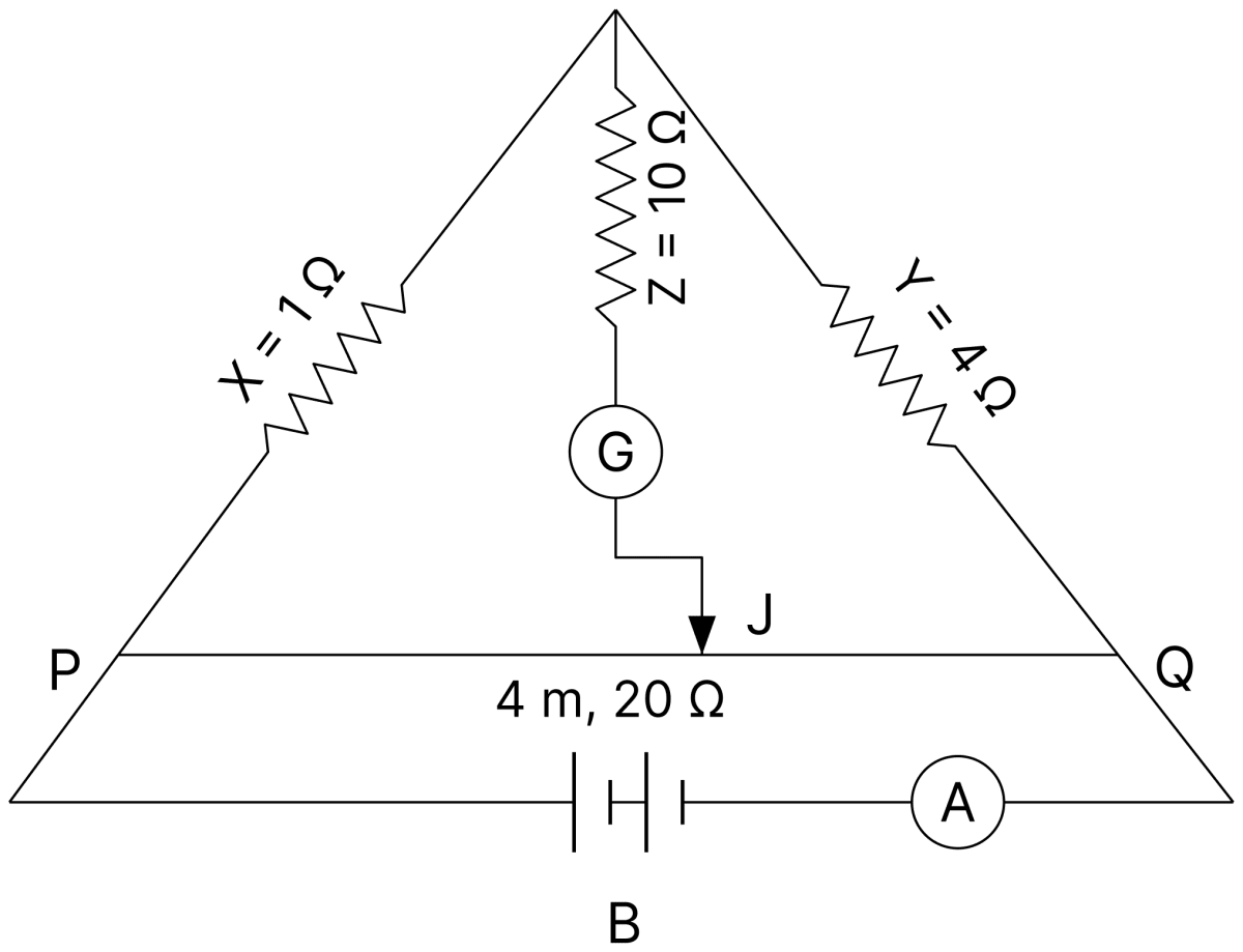
(i) When the jockey J does not touch the wire PQ, what is the reading of ammeter A?
(ii) Where should the jockey J be pressed on the wire PQ, so that the galvanometer G shows no deflection?
Answer
Given,
- Length of PQ = 4 m, resistance of PQ = 20 Ω
- X = 1 Ω, Y = 4 Ω
- Emf of the battery = 10 V, internal resistance = 1 Ω
(i) When the jockey does not touch the wire, no current flows through the galvanometer branch. The path P–X–Y–Q of resistance 1 + 4 = 5 Ω is then in parallel with the wire PQ of resistance 20 Ω,
(ii) For no deflection in the galvanometer the bridge must be balanced,
Hence, the ammeter reads 2 A, and the jockey should be pressed at 0.8 m from P.
A 10 m long potentiometer wire carries a steady current. A standard cell of emf 1.018 V is balanced against a length of 254.5 cm of the wire. What is the potential gradient across the potentiometer wire?
Answer
Given,
- E = 1.018 V
- Balancing length, l = 254.5 cm
At the balance point,
Hence, the potential gradient across the potentiometer wire is 0.004 V/cm.
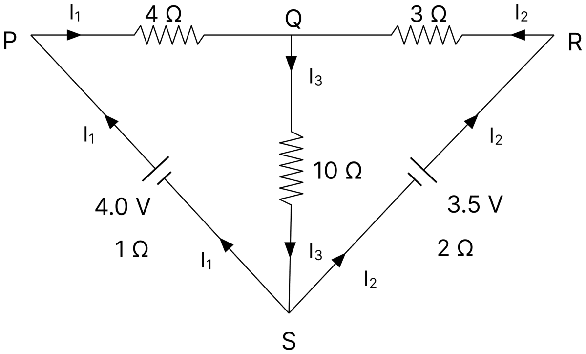
In the circuit shown in figure, E1 and E2 are batteries having emfs 4.0 V and 3.5 V respectively and internal resistance 1 Ω and 2 Ω respectively. Using Kirchhoff's laws, calculate currents I1, I2 and I3.
Answer
Given,
- E1 = 4.0 V, r1 = 1 Ω, with a 4 Ω resistor in its branch
- E2 = 3.5 V, r2 = 2 Ω, with a 3 Ω resistor in its branch
- Middle branch of 10 Ω carrying I3
Junction rule :
Loop containing E1 :
Loop containing E2 :
Substituting Eq. (i) in Eqs. (ii) and (iii),
Multiplying Eq. (iv) by 3 and Eq. (v) by 2 and subtracting,
From Eq. (iv),
Hence, I1 = 0.2 A, I2 = 0.1 A and I3 = 0.3 A.
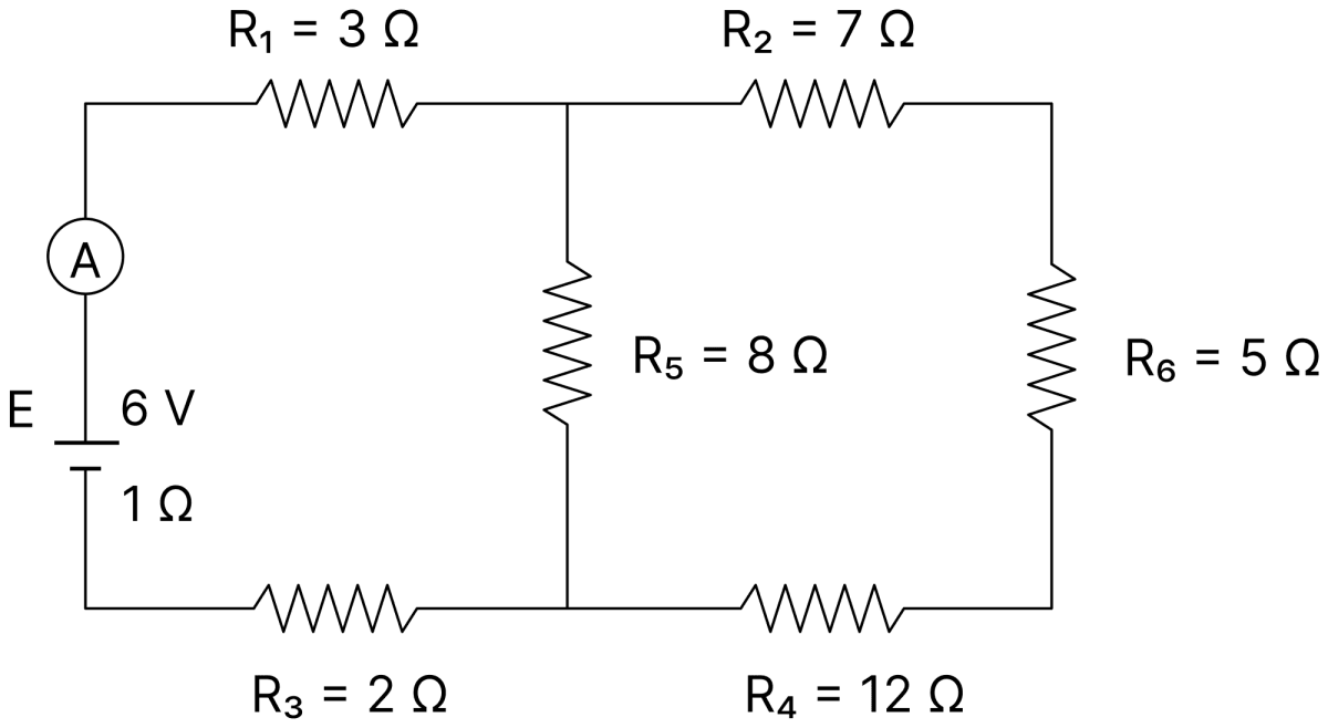
In the circuit shown in figure, E is a battery of emf 6V and internal resistance 1 Ω. Find the reading of the ammeter A, if it has negligible resistance.
Answer
Given,
- E = 6 V, r = 1 Ω
- R1 = 3 Ω, R2 = 7 Ω, R3 = 2 Ω, R4 = 12 Ω, R5 = 8 Ω, R6 = 5 Ω
The path from the junction of R1 and R2 to the junction of R3 and R4, taken through R2, R6 and R4, has resistance
This is in parallel with R5 = 8 Ω joining the same two junctions,
This combination is in series with R1 and R3,
The reading of the ammeter is the current drawn from the battery,
Hence, the ammeter reads 0.5 A.
Five resistors are connected as shown in the figure.
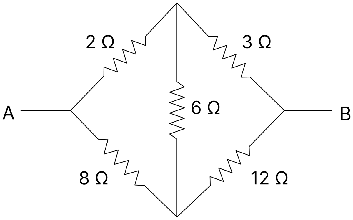
The effective resistance i.e., equivalent resistance between the points A and B is :
- 4 Ω
- 5 Ω
- 15 Ω
- 20 Ω
Answer
4 Ω
The five resistors form a Wheatstone bridge with 2 Ω and 3 Ω in the upper branch, 8 Ω and 12 Ω in the lower branch and 6 Ω as the bridge arm. Testing the condition of balance,
The bridge is balanced, so no current flows through the 6 Ω resistor and it may be omitted. The upper branch gives 2 + 3 = 5 Ω and the lower branch 8 + 12 = 20 Ω, and these are in parallel,
n cells, each of emf e and internal resistance r are joined in the series to form a row. m such rows are connected in parallel to form a battery of N = mn cells. This battery is connected to an external resistance R.
(i) What is the emf of this battery and how much is its internal resistance?
(ii) Show that current I flowing through the external resistance R is given by
Answer
(i) In each row the n cells are joined in series, so the emf of one row is ne and its internal resistance is nr.
The m rows are joined in parallel and all have the same emf, so the emf of the whole battery is
The internal resistances of the m rows, each equal to nr, are in parallel, so
(ii) The current through the external resistance is
Multiplying the numerator and the denominator by m,
Since N = mn,
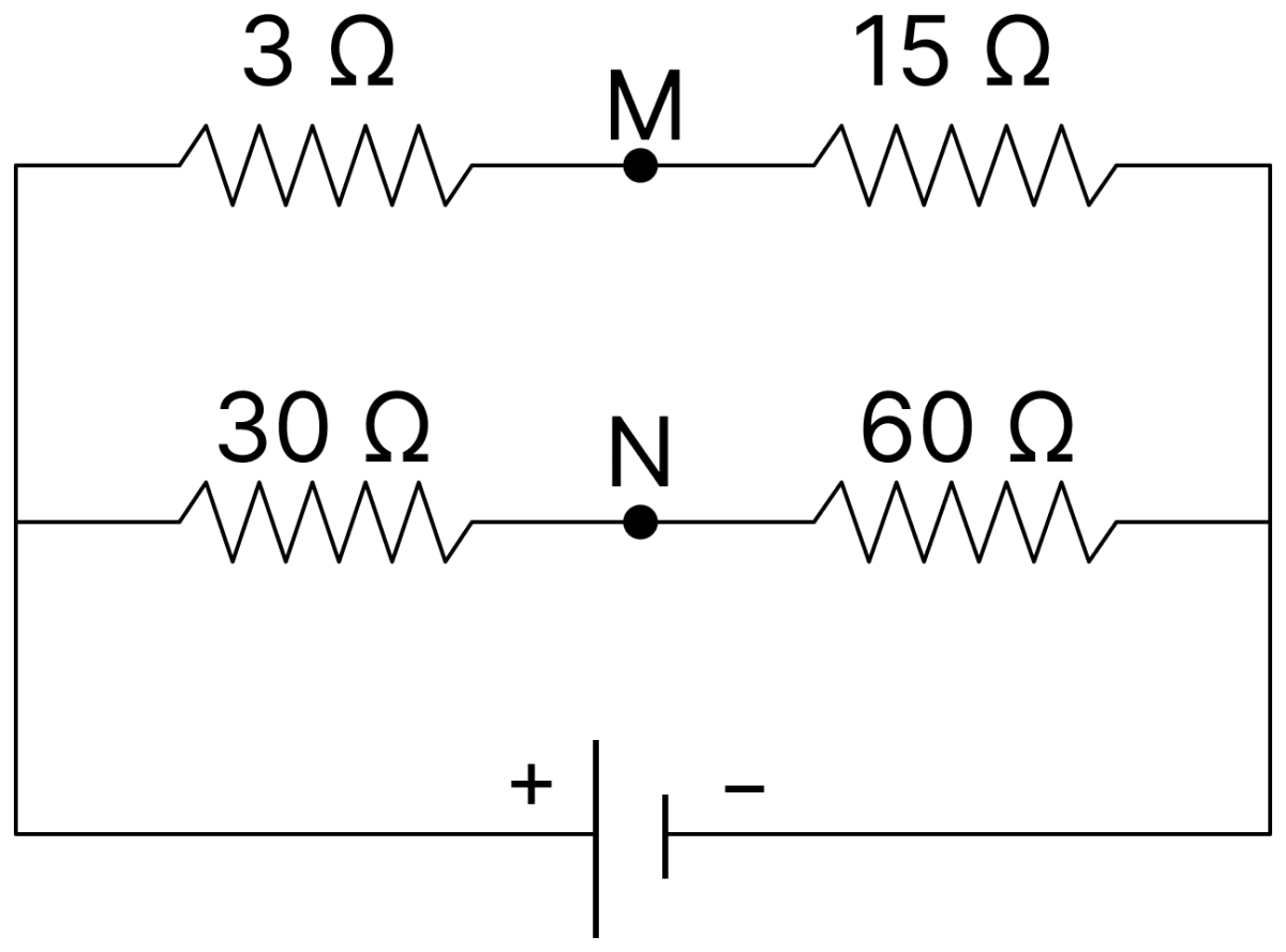
How much resistance should be connected to 15 Ω resistor shown in the circuit in figure, so that the points M and N are at the same potential?
Answer
Given,
- Arms of the network : 3 Ω and 15 Ω in the upper branch, 30 Ω and 60 Ω in the lower branch
For M and N to be at the same potential the bridge must be balanced. If X is the required resistance of the second upper arm, then
Since 6 Ω is less than 15 Ω, a resistance Y must be connected in parallel with the 15 Ω resistor,
Hence, a resistance of 10 Ω should be connected in parallel with the 15 Ω resistor.
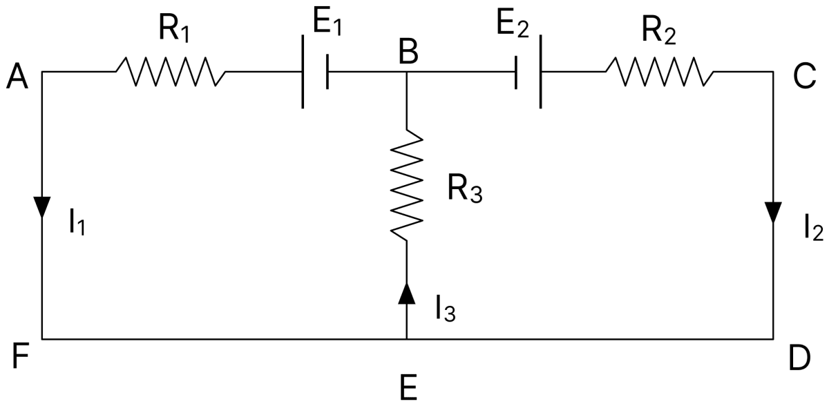
In the circuit shown in figure, E1 = 17 V, E2 = 21 V, R1 = 2 Ω, R2 = 3 Ω and R3 = 5 Ω. Using Kirchhoff's laws, find the currents flowing through the resistors R1, R2 and R3. (Internal resistance of each of the batteries is negligible.)
Answer
Given,
- E1 = 17 V, E2 = 21 V
- R1 = 2 Ω, R2 = 3 Ω, R3 = 5 Ω
Junction rule :
Loop containing E1, R1 and R3 :
Loop containing E2, R2 and R3 :
Substituting Eq. (i) in Eqs. (ii) and (iii),
Multiplying Eq. (iv) by 8 and Eq. (v) by 5 and subtracting,
From Eq. (iv),
Hence, the currents through R1, R2 and R3 are 1 A, 2 A and 3 A respectively.
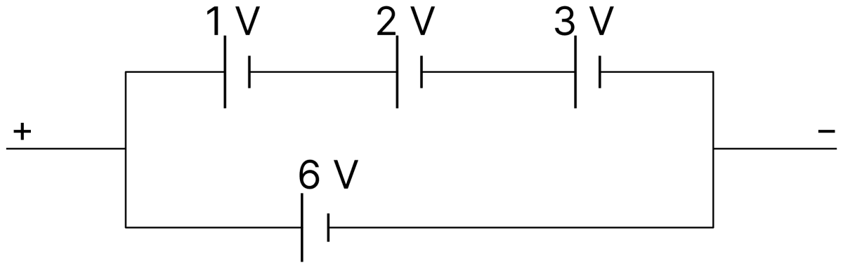
Find the emf of the battery shown in the figure.
Answer
The battery consists of two rows connected in parallel between the same two terminals.
In the upper row the cells of 1 V, 2 V and 3 V are joined in series, so the emf of this row is
The lower row contains a single cell of 6 V.
Since the two rows have the same emf and are connected in parallel, the emf of the combination is equal to the emf of one row.
Hence, the emf of the battery is 6 V.
Draw a labelled circuit diagram of a potentiometer to compare emfs of two cells. Write the working formula (Derivation not required).
Answer
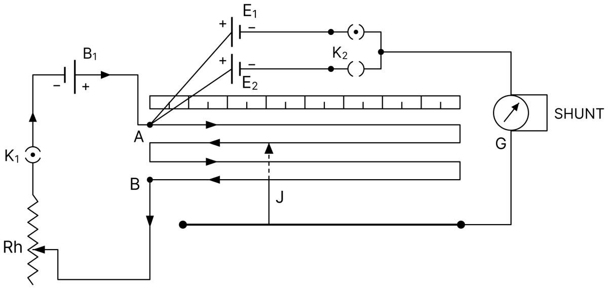
The potentiometer wire AB is connected to the driving cell B1 through a key and a rheostat, forming the primary circuit. The positive terminals of the two cells E1 and E2 are joined to the end A, and their negative terminals are taken through the keys K1 and K2 and the galvanometer to the jockey J.
With K1 closed and K2 open the balance point is obtained at a length l1, and with K2 closed and K1 open it is obtained at a length l2.
Working formula :
A resistor R is connected to a cell of emf e and internal resistance r. Potential difference across the resistor R is found to be V. State the relation between e, V, R and r.
Answer
The current in the circuit is I = V/R, and the terminal potential difference is V = e − Ir. Therefore,
The relation may also be written as
Three identical cells each of emf 2V and internal resistance 1Ω are connected in series to form a battery. The battery is then connected to a parallel combination of two identical resistors, each of resistance 6 Ω. Find the current delivered by the battery.
Answer
Given,
- Emf of each cell = 2 V, internal resistance of each cell = 1 Ω, three cells in series
- Two resistors of 6 Ω each in parallel
Emf and internal resistance of the battery :
External resistance :
Current delivered :
Hence, the current delivered by the battery is 1 A.
A 10 m long uniform metallic wire having a resistance of 20 Ω is used as potentiometer wire. This wire is connected in series with another resistance of 480 Ω and a battery of emf 5V having negligible internal resistance. If an unknown emf e is balanced across 6 m of the potentiometer wire, calculate :
(i) the potential gradient across the potentiometer wire.
(ii) the value of the unknown emf e.
Answer
Given,
- Length of the wire, L = 10 m, resistance of the wire = 20 Ω
- Series resistance = 480 Ω
- Emf of the battery = 5 V, internal resistance negligible
- Balancing length, l = 6 m
(i) Potential gradient : The current in the primary circuit is
The potential difference across the potentiometer wire is
(ii) Unknown emf :
Hence, the potential gradient is 0.02 V/m and the unknown emf is 0.12 V.
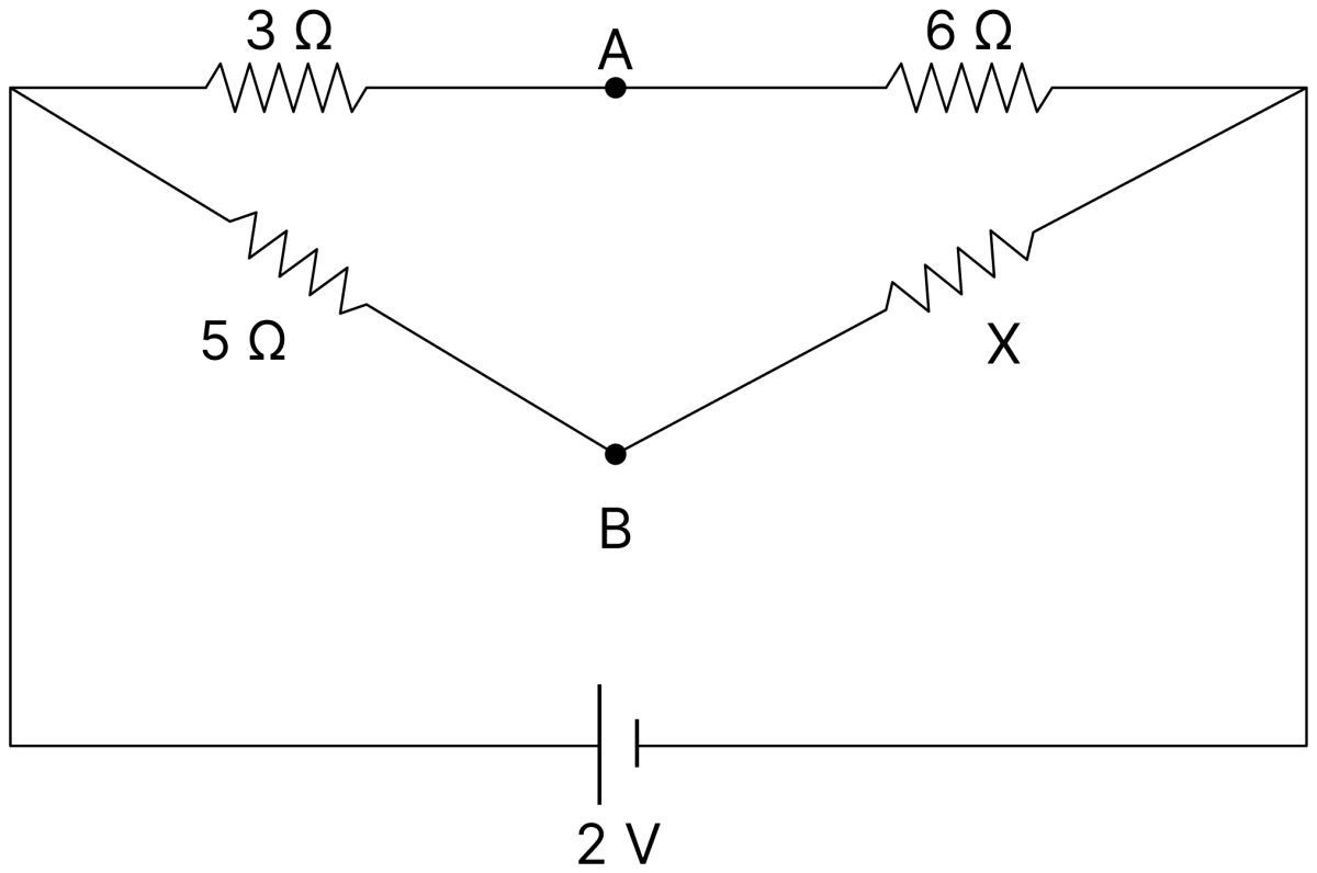
In the figure given, find the value of resistance X for which points A and B are at the same potential?
Answer
Given,
- Resistances 3 Ω and 6 Ω in the upper branch, 5 Ω and X in the lower branch
For A and B to be at the same potential no current flows between them, so the network is a balanced Wheatstone bridge,
Hence, X = 10 Ω.
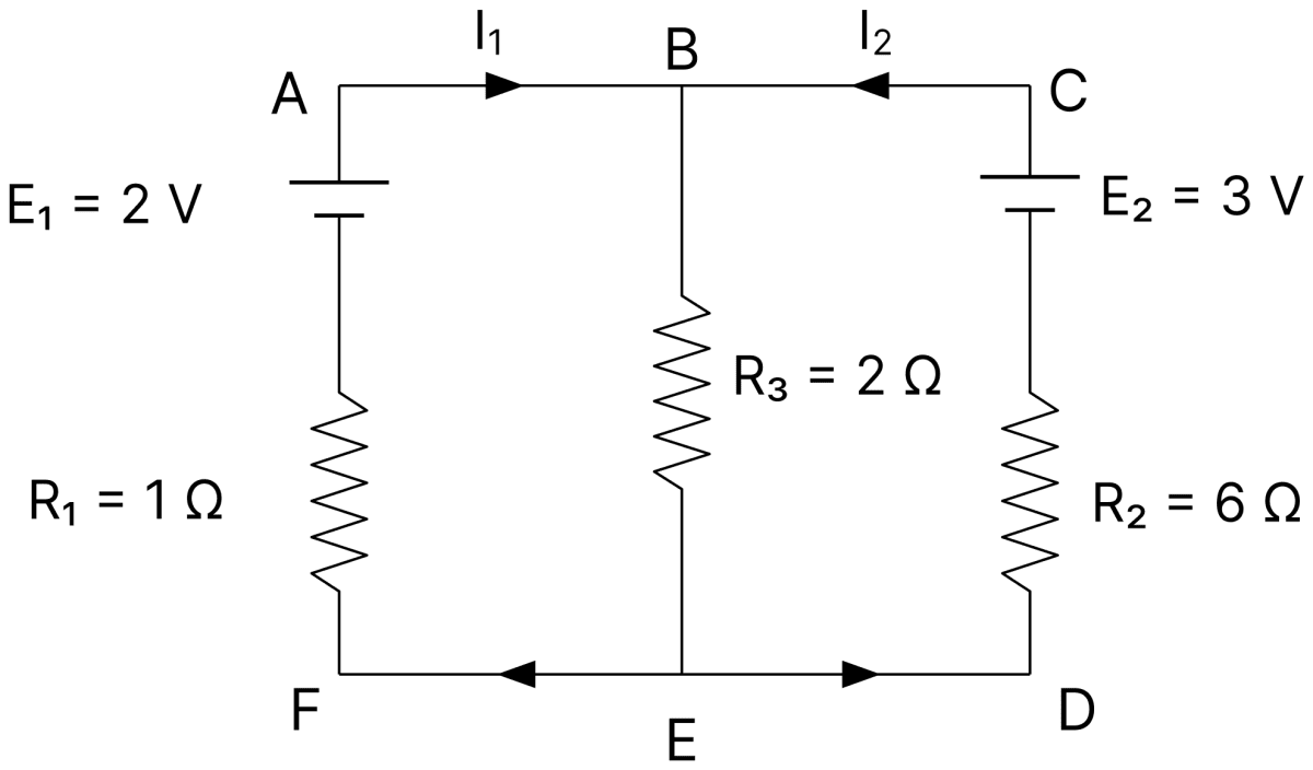
In the circuit shown in figure given, E1 and E2 are cells having emfs 2V and 3V respectively and negligible internal resistances. Applying Kirchhoff's laws of electrical networks, find the values of currents I1 and I2.
Answer
Given,
- E1 = 2 V, E2 = 3 V, internal resistances negligible
- R1 = 1 Ω, R2 = 6 Ω, R3 = 2 Ω
Junction rule : The current through R3 is (I1 + I2).
Loop containing E1, R1 and R3 :
Loop containing E2, R2 and R3 :
Multiplying Eq. (i) by 4 and subtracting Eq. (ii),
From Eq. (i),
Hence, I1 = 0.5 A and I2 = 0.25 A.
Name the two conservation laws implied in Kirchhoff's laws for electric circuits.
Answer
The junction rule follows from the conservation of charge, and the loop rule follows from the conservation of energy.
In a meter bridge circuit, resistance in the left hand gap is 2 Ω and an unknown resistance X is in the right hand gap as shown in figure. The null point is found to be 40 cm from the left end of the wire. What resistance should be connected to X so that the new null point is 50 cm from the left end of the wire?
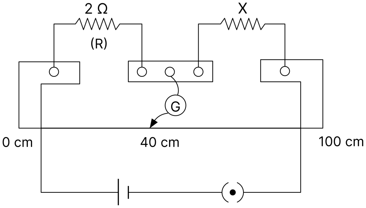
Answer
Given,
- Resistance in the left gap, R = 2 Ω
- Balancing length, l = 40 cm
- Required balancing length, l' = 50 cm
Value of X :
For the null point at 50 cm, the resistance X' of the right gap must be
Since 2 Ω is less than 3 Ω, a resistance Y must be connected in parallel with X,
Hence, a resistance of 6 Ω should be connected in parallel with X.
Figure shows two resistors R1 and R2 connected to a battery having an emf of 40 V and negligible internal resistance. A voltmeter having a resistance of 300 Ω is used to measure potential difference across R1. Find the reading of the voltmeter.
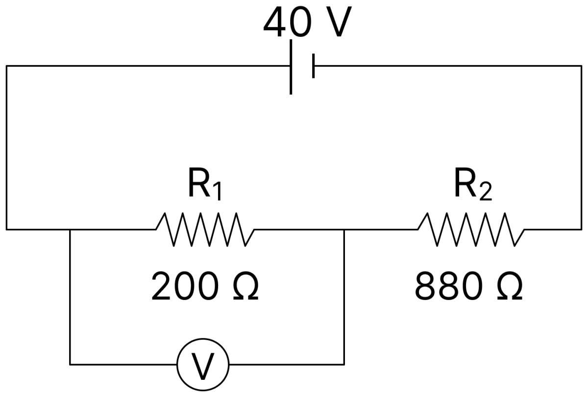
Answer
Given,
- R1 = 200 Ω, R2 = 880 Ω
- Emf of the battery = 40 V, internal resistance negligible
- Resistance of the voltmeter = 300 Ω
The voltmeter is in parallel with R1,
The total resistance of the circuit is
The reading of the voltmeter is the potential difference across the parallel combination,
Hence, the voltmeter reads 4.8 V.
In a potentiometer experiment, balancing length is found to be 120 cm for a cell E1 of emf 2 V. What will be the balancing length for another cell E2 of emf 1.5 V? (No other changes are made in the experiment.)
Answer
Given,
- E1 = 2 V, l1 = 120 cm
- E2 = 1.5 V
Since the balancing length is proportional to the emf,
Hence, the balancing length for the other cell is 90 cm.
ε1 and ε2 are two batteries having emf of 34 V and 10 V respectively and internal resistance of 1Ω and 2Ω respectively. They are connected as shown in figure. Using Kirchhoff's laws of electrical networks, calculate the currents I1 and I2.
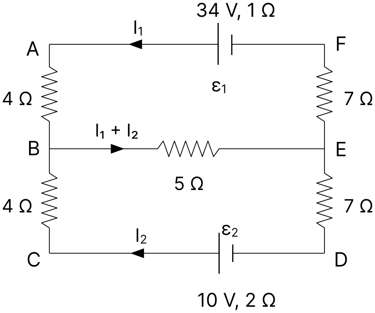
Answer
Given,
- ε1 = 34 V, r1 = 1 Ω ; ε2 = 10 V, r2 = 2 Ω
- Resistances 4 Ω and 4 Ω in the left branch, 7 Ω and 7 Ω in the right branch, and 5 Ω in the middle branch carrying (I1 + I2)
Loop containing ε1 :
Loop containing ε2 :
Multiplying Eq. (i) by 18 and Eq. (ii) by 5 and subtracting,
From Eq. (ii),
Hence, I1 = 2 A and I2 = 0.
In a potentiometer experiment, the balancing length with a resistance of 2 Ω is found to be 100 cm, while that of an unknown resistance is 500 cm. Calculate the value of the unknown resistance.
Answer
Given,
- R = 2 Ω, l1 = 100 cm
- l2 = 500 cm
The same current flows through both the resistors, so the potential difference across each is proportional to its resistance, and hence to the balancing length,
Hence, the unknown resistance is 10 Ω.
Calculate the net emf across A and B shown in given figure.
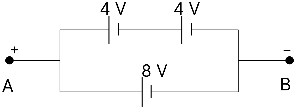
Answer
The arrangement consists of two rows connected in parallel between A and B.
In the upper row the two cells of 4 V each are joined in series, so the emf of this row is
The lower row contains a single cell of 8 V.
Since both the rows have the same emf and are connected in parallel, the net emf of the combination is equal to the emf of one row.
Hence, the net emf across A and B is 8 V.
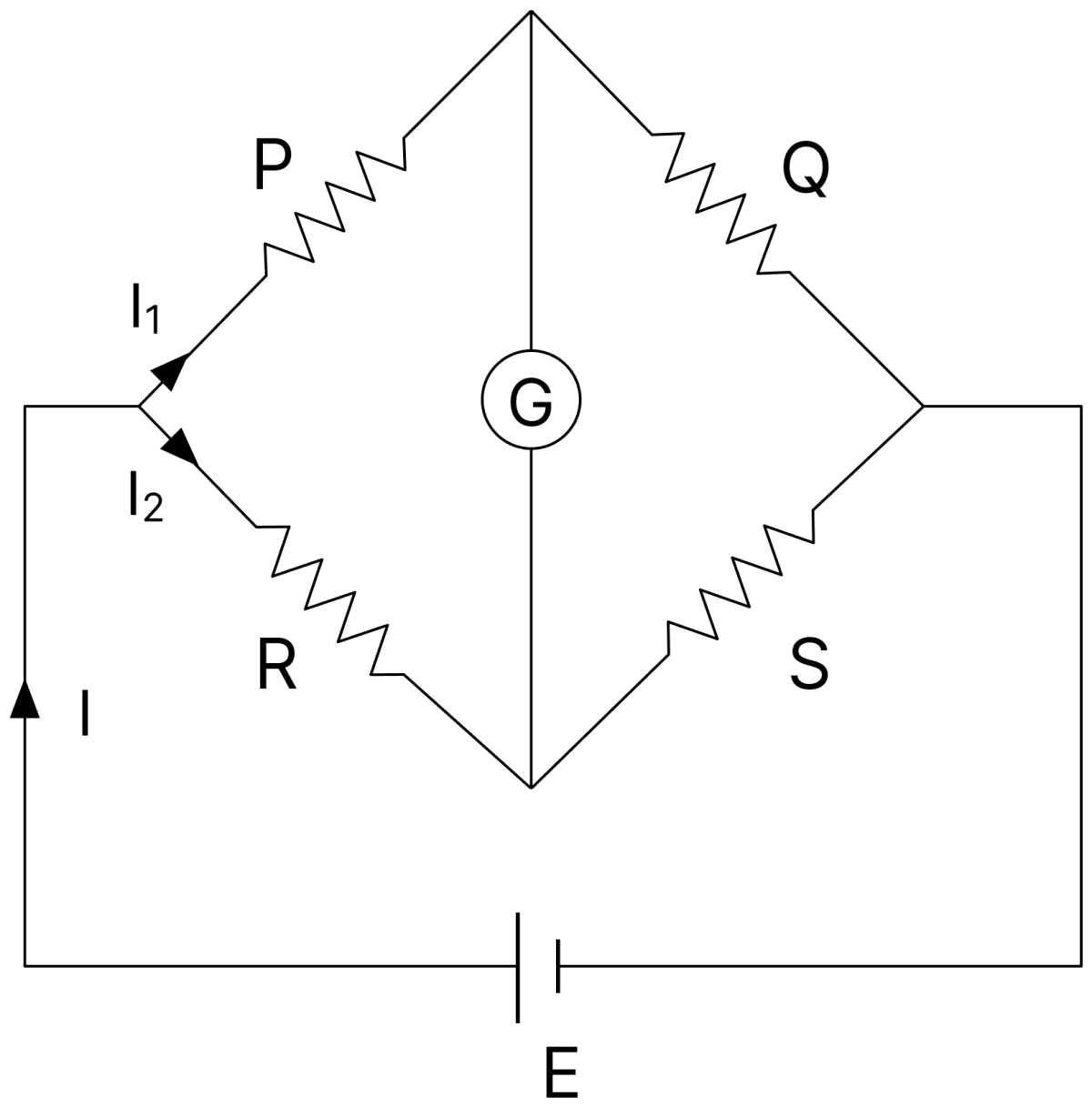
(i) Obtain the balancing condition for the Wheatstone bridge arrangement as shown in figure.
(ii) Draw a labelled circuit diagram of a potentiometer to measure the internal resistance 'r' of a cell. Write the working formula. (Derivation is not required).
Answer
(i) Balancing condition : Four resistances P, Q, R and S are connected in the four arms of the bridge, a cell E is connected across one diagonal and a galvanometer G across the other.
The bridge is balanced when the galvanometer shows no deflection. In this condition no current flows through the galvanometer, so the two junctions joined by it are at the same potential.
Let the current I1 flow through P and Q, and the current I2 through R and S. Then the potential drops across P and R are equal, and so are those across Q and S,
Dividing Eq. (i) by Eq. (ii),
(ii) Potentiometer for internal resistance :
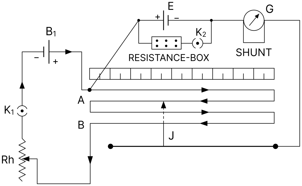
The cell of emf E whose internal resistance is to be measured is joined in the secondary circuit through a galvanometer, and a resistance box R with a key is connected across it. With the key open the balancing length is l1, and with a resistance R introduced and the key closed it is l2.
Working formula :
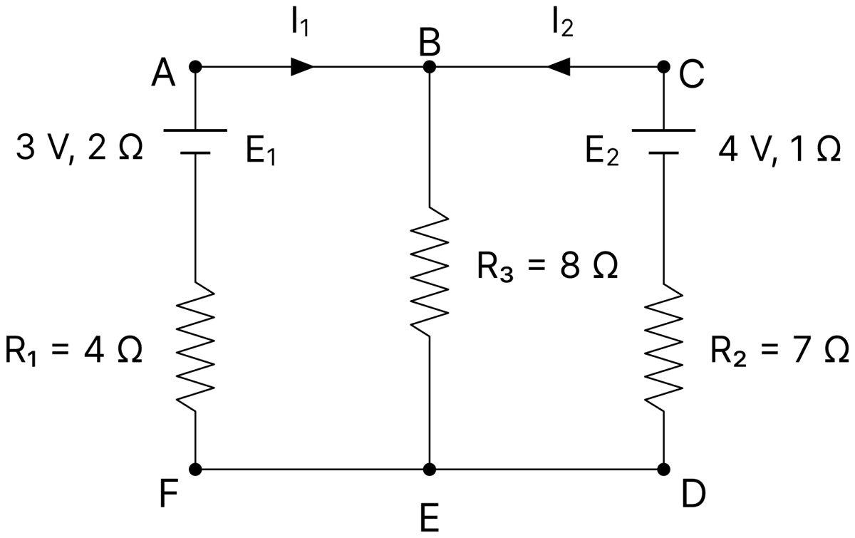
E1 and E2 are two batteries having emfs of 3V and 4V and internal resistance of 2 Ω and 1 Ω respectively. They are connected as shown in figure. Using Kirchhoff's laws of electrical circuits, calculate the current I1 and I2.
Answer
Given,
- E1 = 3 V, r1 = 2 Ω, with R1 = 4 Ω in its branch
- E2 = 4 V, r2 = 1 Ω, with R2 = 7 Ω in its branch
- R3 = 8 Ω in the middle branch carrying (I1 + I2)
Loop containing E1 :
Loop containing E2 :
Multiplying Eq. (i) by 2 and subtracting Eq. (ii),
From Eq. (ii),
Hence, I1 = 0.1 A and I2 = 0.2 A.
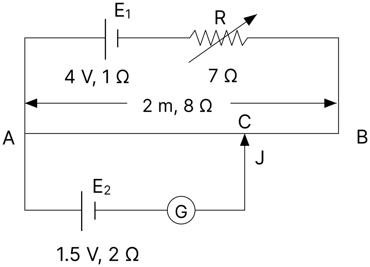
A potentiometer circuit is shown in figure. AB is a uniform metallic wire having length of 2 m and resistance of 8 Ω. The batteries E1 and E2 have emfs of 4V and 1.5V and their internal resistances are 1Ω and 2Ω respectively.
(i) When the jockey J does not touch the wire AB, calculate:
(a) the current flowing through the potentiometer wire AB.
(b) the potential gradient across the wire AB.
(ii) Now the jockey J is made to touch the wire AB at a point C such that the galvanometer (G) shows no deflection. Calculate the length AC.
Answer
Given,
- Length of AB = 2 m, resistance of AB = 8 Ω
- E1 = 4 V, r1 = 1 Ω, series resistance R = 7 Ω
- E2 = 1.5 V, r2 = 2 Ω
(i) (a) Current through AB : When the jockey does not touch the wire, no current is drawn by the secondary circuit, so the current in the primary circuit is
(b) Potential gradient : The potential difference across AB is
(ii) Length AC : At the balance point the potential difference across AC equals the emf of E2,
Hence, I = 0.25 A, K = 1 V m-1 and AC = 1.5 m.
With the help of a neatly drawn and labelled diagram, obtain balancing condition of a Wheatstone bridge.
Answer
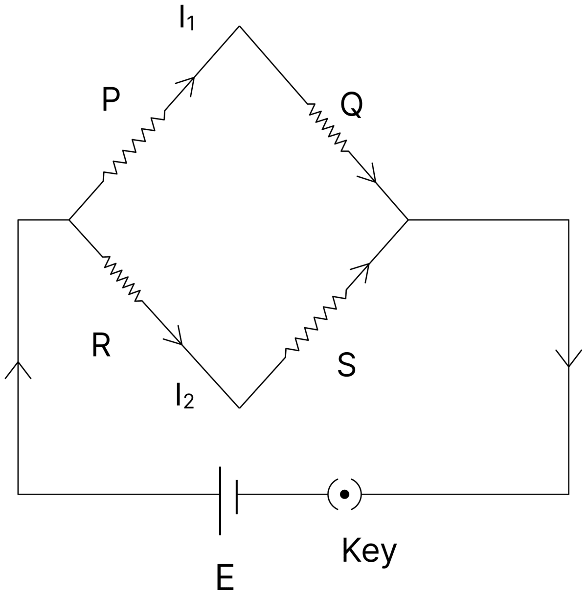
Four resistances P, Q, R and S are connected in the four arms of the bridge. A cell E with a key is connected across one diagonal and a galvanometer G across the other diagonal.
The bridge is said to be balanced when the galvanometer shows no deflection. In this condition no current flows through the galvanometer, so the two junctions joined by it are at the same potential.
Let the current I1 flow through P and Q, and the current I2 through R and S. Since the two junctions are at the same potential, the potential drops across P and R are equal, and so are those across Q and S,
Dividing Eq. (i) by Eq. (ii),
This is the balancing condition of the Wheatstone bridge.
Draw the circuit diagram for the determination of the internal resistance of a cell using a potentiometer.
Answer
The potentiometer wire AB is joined to the driving cell B1 through a key K1 and a rheostat, forming the primary circuit. The cell of emf E whose internal resistance is to be determined is connected between the end A and the jockey J through a galvanometer, and a resistance box R with a key K2 is connected across this cell.
With the key K2 open the balancing length l1 corresponds to the emf E, and with a resistance R introduced and K2 closed the balancing length l2 corresponds to the terminal potential difference V. The internal resistance is then
In a meter bridge circuit, resistance in the left gap is 4 Ω and an unknown resistance R is in the right-hand gap as shown in given figure. The null point is found to be 40 cm from the left end of the wire.
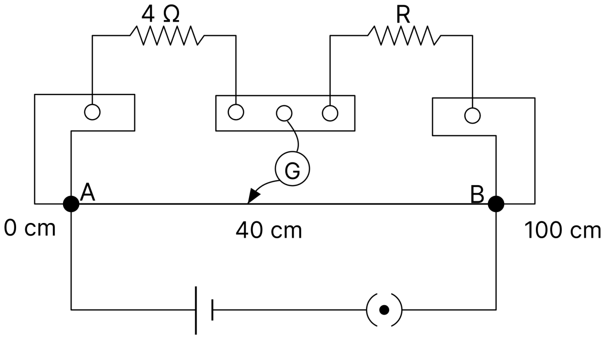
(i) Calculate the value of unknown resistance R.
(ii) What change will you make in R to bring the null point to the mid-point of the wire AB?
Answer
Given,
- Resistance in the left gap = 4 Ω
- Balancing length, l = 40 cm
(i) Value of R :
(ii) For the null point at the mid-point, l' = 50 cm, so the resistance of the right gap must be
A resistance Y must therefore be connected in parallel with R,
Hence, R = 6 Ω, and a 12 Ω resistance should be connected in parallel with R so that their equivalent resistance becomes 4 Ω.
Six identical cells, each of emf 1.5V and internal resistance 0.5 Ω are connected in series to form a battery. The battery is then connected to an external resistor of 9 Ω. Calculate:
(i) the emf of the battery.
(ii) the current flowing in the circuit.
Answer
Given,
- Number of cells, n = 6, each of emf 1.5 V and internal resistance 0.5 Ω
- External resistance, R = 9 Ω
(i) Emf of the battery :
(ii) Current in the circuit : The total internal resistance is
Hence, the emf of the battery is 9 V and the current in the circuit is 0.75 A.
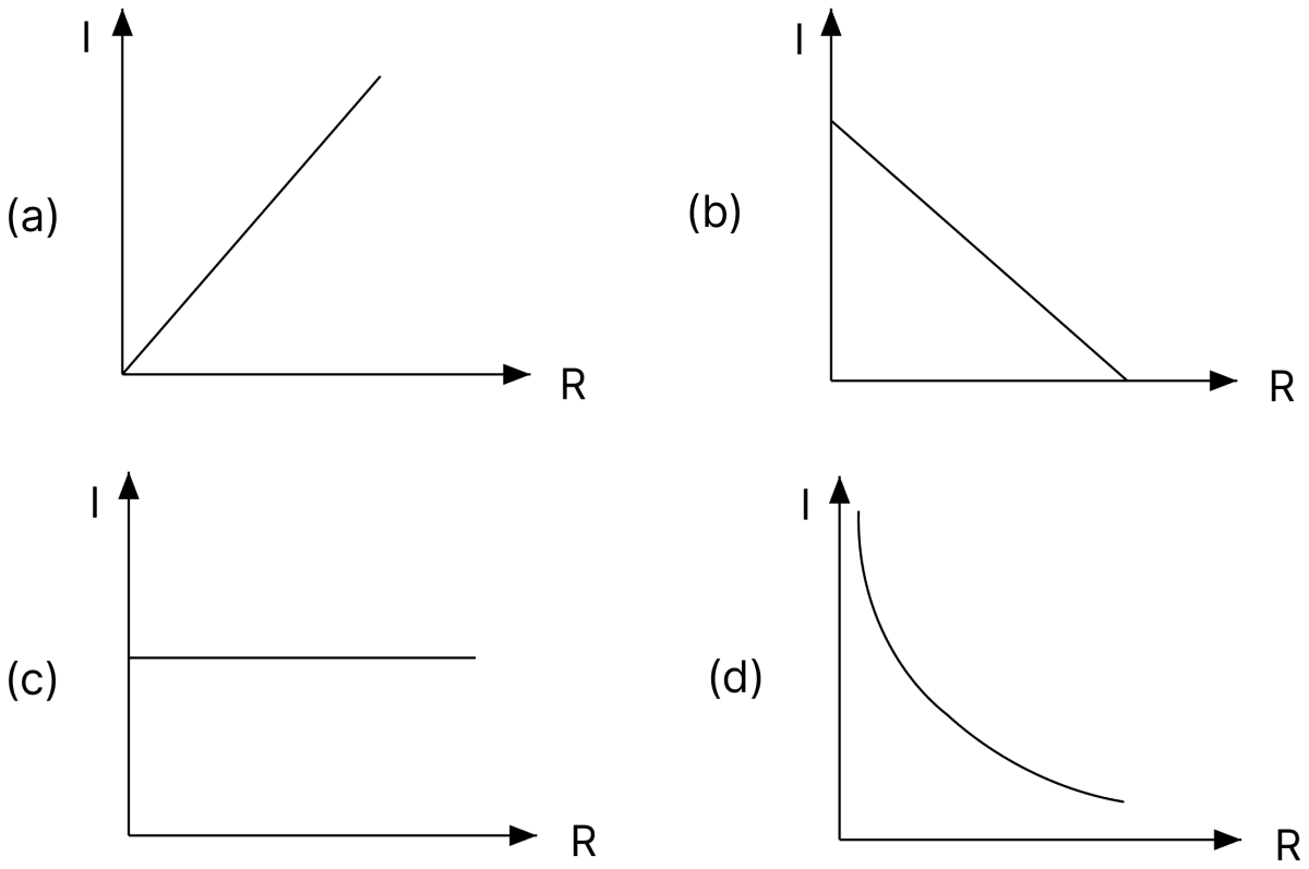
If a variable resistance is connected to a cell of constant emf, then the graph which represents the correct relationship between current I and resistance R is:
Answer
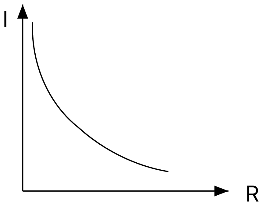
The current drawn from a cell of constant emf E and internal resistance r is
Thus I decreases as R increases, but not linearly. When R = 0 the current has its maximum value E/r, and as R becomes very large the current tends to zero without ever becoming negative. The graph is therefore a curve falling steeply at first and then flattening out, which is shown only in option (d).
A battery sends a current of 1.5A through an external resistance of 1.0 Ω. If internal resistance of the battery is 0.5 Ω, its emf is:
- 2.00V
- 2.25V
- 2.50V
- 2.75V
Answer
2.25V
Given, I = 1.5 A, R = 1.0 Ω and r = 0.5 Ω.
N identical cells each of emf 'e' and internal resistance 'r' are connected in series to form a row. M such rows are connected in parallel to form a battery. When an external resistance R is connected to the battery, current flowing through it is:
- MNe/(R + r)
- MNe/(NR + Mr)
- MNe/(MR + Nr)
- Ne/(MR + Nr)
Answer
MNe/(MR + Nr)
Each row of N cells in series has an emf Ne and an internal resistance Nr. The M rows in parallel give an emf Ne and an internal resistance Nr/M. Hence
Kirchhoff's junction rule is based on the principle of conservation of:
- energy
- charge
- momentum
- momentum and energy
Answer
charge
The junction rule states that the total current arriving at a junction equals the total current leaving it. Since current is the rate of flow of charge, no charge is accumulated at the junction, so the rule follows from the conservation of charge.
Wheatstone bridge principle is used to measure :
- resistance of a wire
- potential difference across a resistor
- current flowing through a wire
- emf of a cell
Answer
resistance of a wire
At balance the Wheatstone bridge gives P/Q = R/S, so an unknown resistance can be found from three known resistances. The meter bridge, which is the practical form of the Wheatstone bridge, is used to determine the resistance of a wire and hence the specific resistance of its material.
In a potentiometer, balancing length with a standard cell of emf 1.08 V is 21.6 cm. Balancing length with a cell of emf 1.50 V will be :
- 21.6 cm
- 30.0 cm
- 45.0 cm
- 60.0 cm
Answer
30.0 cm
Since the balancing length is proportional to the emf,
If potential difference across 80 cm of a potentiometer wire is 2V, potential gradient across the wire is :
- 0.025 Vm-1
- 0.050 Vm-1
- 0.075 Vm-1
- 2.50 Vm-1
Answer
2.50 Vm-1
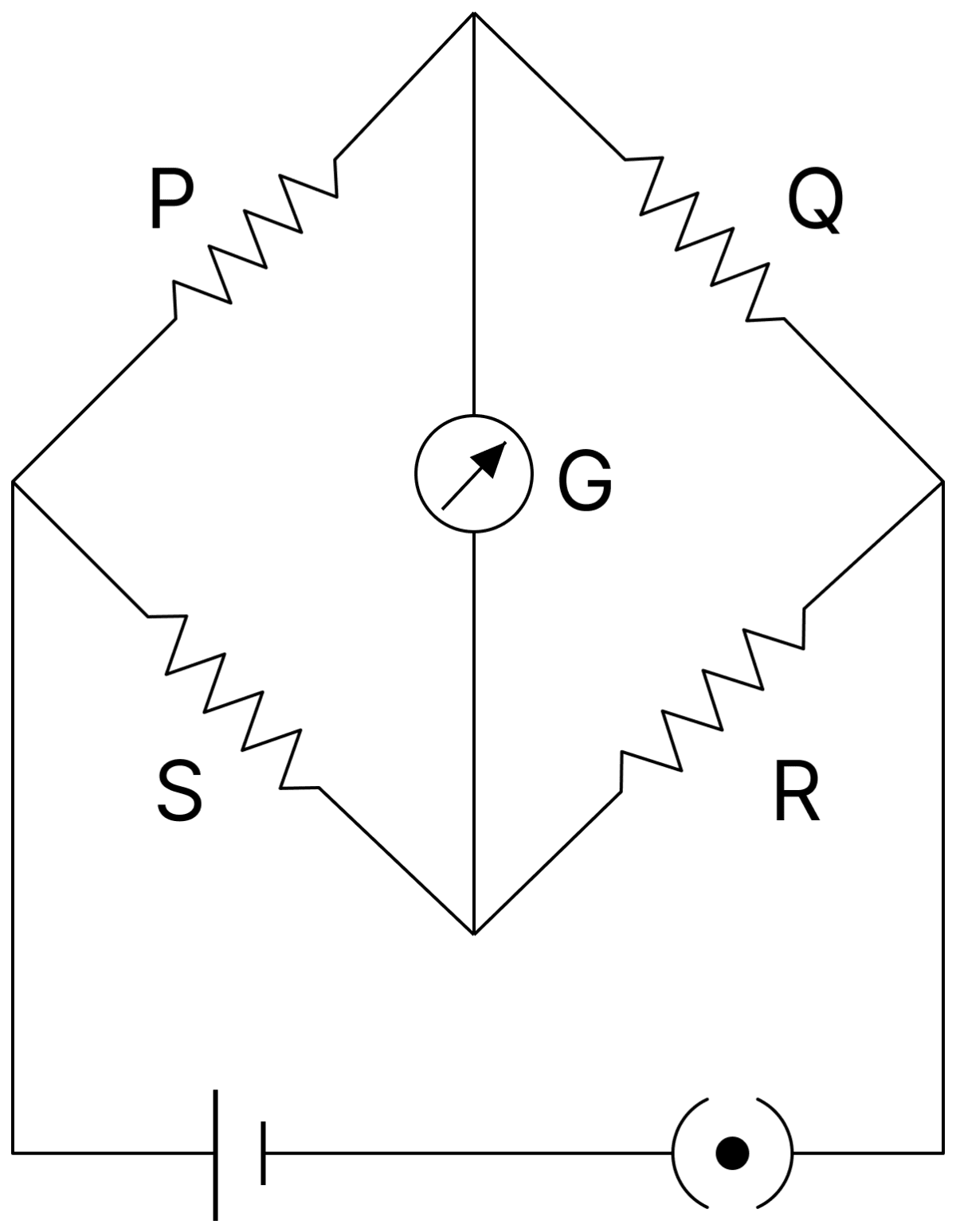
In the Wheatstone bridge circuit shown in figure, P = 10 Ω, Q = 20 Ω, R = 200 Ω and S = 100 Ω, emf of the battery being 2V. The current flowing through the galvanometer is:
- 0
- 1A
- 2A
- 3A
Answer
0
Testing the condition of balance for the bridge as connected in the figure,
The two ratios are equal, so the bridge is balanced. The two junctions joined by the galvanometer are then at the same potential and no current flows through it.
Eight identical cells, each of emf 2V and internal resistance 3Ω, are connected in series to form a row. Six such rows are connected in parallel to form a battery. This battery is now connected to an external resistor R of resistance 6Ω. Calculate :
(i) emf of the battery.
(ii) internal resistance of the battery.
(iii) current flowing through R.
Answer
Given,
- n = 8 cells in each row, each of emf 2 V and internal resistance 3 Ω
- m = 6 rows in parallel
- External resistance, R = 6 Ω
(i) Emf of the battery : All the rows have the same emf, so
(ii) Internal resistance : Each row has an internal resistance of 8 × 3 = 24 Ω, and the six rows are in parallel,
(iii) Current through R :
Hence, E = 16 V, r = 4 Ω and I = 1.6 A.
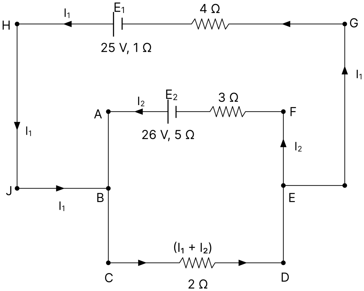
In the circuit shown in figure, E1 and E2 are batteries having emfs of 25 V and 26 V. They have an internal resistance of 1Ω and 5Ω, respectively. Applying Kirchhoff's laws of electrical networks, calculate the currents I1 and I2.
Answer
Given,
- E1 = 25 V, r1 = 1 Ω, with a 4 Ω resistor in its branch
- E2 = 26 V, r2 = 5 Ω, with a 3 Ω resistor in its branch
- A 2 Ω resistor in the common branch carrying (I1 + I2)
Loop containing E1 :
Loop containing E2 :
Multiplying Eq. (i) by 5 and subtracting Eq. (ii),
From Eq. (i),
Hence, I1 = 3 A and I2 = 2 A.
Two identical cells, when connected in series or in parallel, deliver the same current to an external resistance of 10 Ω. Calculate internal resistance of each cell.
Answer
Given,
- External resistance, R = 10 Ω
- Current in series = current in parallel
For two identical cells of emf E and internal resistance r,
Hence, the internal resistance of each cell is 10 Ω.
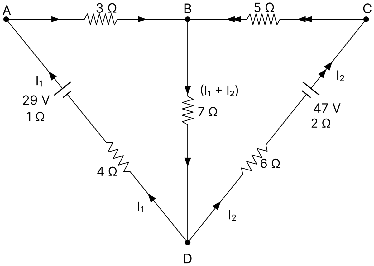
An electrical circuit is shown in the given figure. Apply Kirchhoff's laws of electrical networks to any two loops and calculate the values of currents I1 and I2.
Answer
Given,
- Cell of 29 V with internal resistance 1 Ω, with 3 Ω and 4 Ω resistors in its branch, carrying I1
- Cell of 47 V with internal resistance 2 Ω, with 5 Ω and 6 Ω resistors in its branch, carrying I2
- A 7 Ω resistor in the common branch BD carrying (I1 + I2)
Loop containing the 29 V cell :
Loop containing the 47 V cell :
Multiplying Eq. (i) by 20 and Eq. (ii) by 7 and subtracting,
From Eq. (i),
Hence, I1 = 1 A and I2 = 2 A.
A metre bridge is balanced with a known resistance (R) in the left hand gap and an unknown resistance (S) in the right hand gap. Balance point is found to be at a distance of l cm from the left hand side. When the battery and the galvanometer are interchanged, balance point will :
- shift towards left
- shift towards right
- remain same
- shift towards left or right depending on the values of R and S
Answer
remain same
The balancing condition of the bridge, R/S = l/(100 − l), is obtained from the fact that at balance no current flows through the galvanometer and the two junctions across it are at the same potential.
This condition involves only the four resistances of the arms, and is unaltered if the cell and the galvanometer are interchanged. Hence the balance point remains at the same position.
Three identical cells each of emf 'e' are connected in parallel to form a battery. What is the emf of the battery?
Answer
The emf of the battery is e.
When identical cells are connected in parallel, the positive terminals are joined together and so are the negative terminals. The emf of the combination is therefore the same as that of a single cell, that is, e. Only the internal resistance is reduced, becoming r/3.
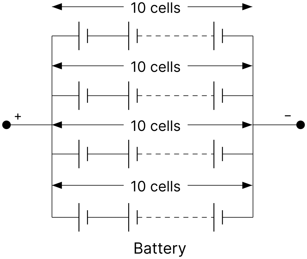
Forty identical cells each of emf 1.45 V and an internal resistance of 0.5 Ω are joined to form a battery as shown in figure.
Calculate its :
(i) emf.
(ii) internal resistance.
Answer
Given,
- Total number of cells = 40, each of emf 1.45 V and internal resistance 0.5 Ω
- The cells are arranged in 4 rows of 10 cells each, the rows being in parallel
(i) Emf of the battery : In each row the 10 cells are in series,
All the four rows have the same emf and are in parallel, so the emf of the battery is 14.5 V.
(ii) Internal resistance : Each row has an internal resistance of 10 × 0.5 = 5 Ω, and the four rows are in parallel,
Hence, the emf of the battery is 14.5 V and its internal resistance is 1.25 Ω.
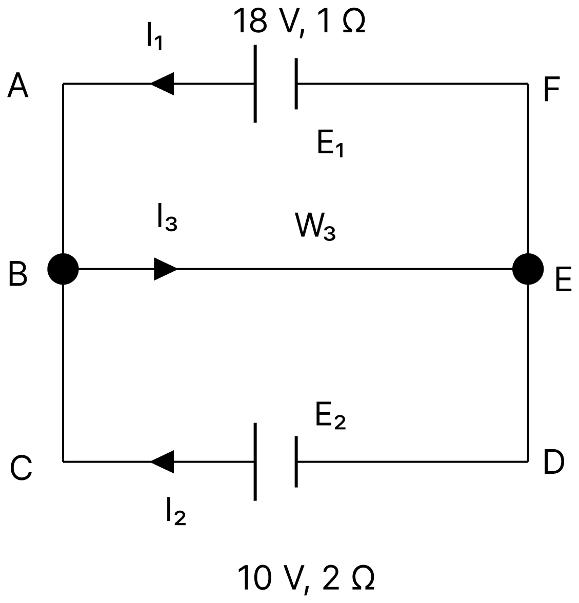
(i) Figure shows two batteries E1 and E2 having emfs of 18 V and 10 V and internal resistance of 1Ω and 2Ω respectively. W1, W2 and W3 are uniform metallic wires, AC, FD and BE having resistance of 8Ω, 6Ω and 10Ω respectively. B and E are midpoints of the wires W1 and W2. Using Kirchhoff's laws of electrical circuits, calculate the current flowing in the wire W3.
(ii) Figure shows a potentiometer circuit in which the driver cell D has an emf of 6 V and internal resistance of 2Ω. The potentiometer wire AB is 10 m long and has a resistance of 28Ω. The series resistance Rs is of 20Ω.
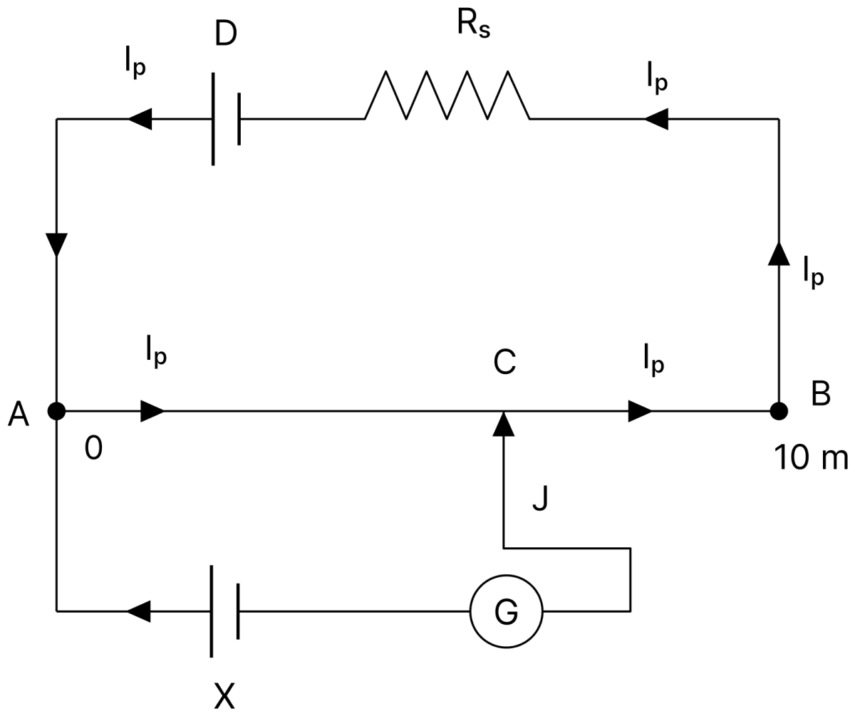
Calculate :
(a) The current Ip flowing in the potentiometer wire AB when the jockey (J) does not touch the wire AB.
(b) emf of the cell X if the balancing length AC is 4.5 m.
Answer
(i)
Given,
- E1 = 18 V, r1 = 1 Ω ; E2 = 10 V, r2 = 2 Ω
- W1 (AC) = 8 Ω, W2 (FD) = 6 Ω, W3 (BE) = 10 Ω
Since B and E are the mid-points of W1 and W2,
Let I1 be the current in the upper loop and I2 that in the lower loop, so that the current in W3 is I3 = I1 + I2.
Upper loop :
Lower loop :
Multiplying Eq. (i) by 19 and Eq. (ii) by 10 and subtracting,
From Eq. (i),
Hence, the current flowing in the wire W3 is 1 A.
(ii)
Given,
- Emf of the driver cell, ED = 6 V, internal resistance = 2 Ω
- Length of AB = 10 m, resistance of AB = 28 Ω
- Series resistance, Rs = 20 Ω
- Balancing length, AC = 4.5 m
(a) Current in the potentiometer wire : When the jockey does not touch the wire, no current is drawn by the secondary circuit,
(b) Emf of the cell X : The potential difference across AB is
Hence, Ip = 0.12 A and the emf of the cell X is 1.512 V.
Which conservation principle is Kirchhoff's junction rule based on?
Answer
Kirchhoff's junction rule is based on the conservation of charge.