KnowledgeBoat Logo
|
OPEN IN APP

Chapter 6

DC Circuits and Measurements — Competition Zone

Class 12 - Nootan Physics


Competition Zone — Multiple Choice Questions

Question 1

A potentiometer wire of length L and a resistance r are connected in series with a battery of emf E0 and a resistance r1. An unknown emf E is balanced at a length l of the potentiometer wire. The emf E will be given by :

  1. E0r(r+r1)⋅lL\dfrac{\text E_0 \text r}{(\text r + \text r_1)} \cdot \dfrac{\text l}{\text L}
  2. E0lL\dfrac{\text E_0 \text l}{\text L}
  3. LE0r(r+r1)l\dfrac{\text L \text E_0 \text r}{(\text r + \text r_1)\text l}
  4. LE0rlr1\dfrac{\text L \text E_0 \text r}{\text l \text r_1}

Answer

E0r(r+r1)⋅lL\dfrac{\text E_0 \text r}{(\text r + \text r_1)} \cdot \dfrac{\text l}{\text L}

Reason — The current in the potentiometer wire is

I=E0r+r1\text I = \dfrac{\text E_0}{\text r + \text r_1}

The potential difference across the whole wire of resistance r is

V=IrV=E0rr+r1\text V = \text{Ir} \\[1em] \text V = \dfrac{\text E_0 \text r}{\text r + \text r_1}

Hence the potential gradient along the wire is

K=VLK=E0r(r+r1)L\text K = \dfrac{\text V}{\text L} \\[1em] \text K = \dfrac{\text E_0 \text r}{(\text r + \text r_1)\text L}

At the balance point,

E=KlE=E0r(r+r1)⋅lL\text E = \text{Kl} \\[1em] \text E = \dfrac{\text E_0 \text r}{(\text r + \text r_1)} \cdot \dfrac{\text l}{\text L}

Question 2

A, B and C are voltmeters of resistance R, 1.5 R and 3 R respectively as shown in figure. When some potential difference is applied between X and Y, the voltmeters readings are VA, VB and VC respectively, then :
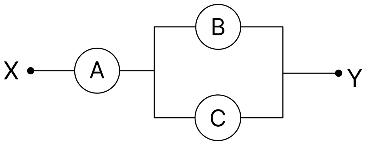
A, B and C are voltmeters of resistance R, 1.5 R and 3 R respectively as shown in figure. When some potential difference is applied between X and Y, the voltmeters readings are V A, V B and V C respectively, then:. DC Circuits and Measurements, Nootan Physics Solutions ICS Class 12
  1. VA ≠ VB = VC
  2. VA = VB ≠ VC
  3. VA ≠ VB ≠ VC
  4. VA = VB = VC

Answer

VA = VB = VC

Reason — The voltmeters B and C are connected in parallel, so their equivalent resistance is

Rp=1.5 R×3 R1.5 R+3 RRp=4.5 R24.5 RRp=R\text R_\text p = \dfrac{1.5\ \text R \times 3\ \text R}{1.5\ \text R + 3\ \text R} \\[1em] \text R_\text p = \dfrac{4.5\ \text R^2}{4.5\ \text R} \\[1em] \text R_\text p = \text R

This parallel combination is in series with A, whose resistance is also R. Since the same current passes through A and through the combination, and their resistances are equal, the potential difference across each is the same.

Being in parallel, B and C have the same potential difference across them. Hence VA = VB = VC.

Question 3

A potentiometer wire has length 4 m and resistance 8 Ω. The resistance that must be connected in series with the wire and an accumulator of emf 2 V, so as to get a potential gradient 1 mV per cm on the wire is :

  1. 40 Ω
  2. 44 Ω
  3. 48 Ω
  4. 32 Ω

Answer

32 Ω

Reason — The required potential gradient is

K=1 mV/cmK=0.1 V/m\text K = 1\ \text{mV/cm} \\[1em] \text K = 0.1\ \text{V/m}

The potential difference across the whole wire of length 4 m is

V=KLV=0.1×4V=0.4 V\text V = \text{KL} \\[1em] \text V = 0.1 \times 4 \\[1em] \text V = 0.4\ \text V

The current in the wire is

I=VRwireI=0.48I=0.05 A\text I = \dfrac{\text V}{\text R_\text{wire}} \\[1em] \text I = \dfrac{0.4}{8} \\[1em] \text I = 0.05\ \text A

The total resistance of the circuit is

20.05=40 Ω\dfrac{2}{0.05} = 40\ \Omega

Hence the resistance to be connected in series is

40−8=32 Ω40 - 8 = 32\ \Omega

Question 4

The potential difference (VA − VB) between the points A and B is given in fig. is :

The potential difference (V A − V B ) between the points A and B is given in fig. is:. DC Circuits and Measurements, Nootan Physics Solutions ICS Class 12
  1. +9 V
  2. −3 V
    • 3 V
    • 6 V

Answer

+9 V

Reason — A current of 2 A flows from A to B. Going from A to B, the potential falls across each resistor in the direction of the current, and also falls on passing through the cell from its positive to its negative terminal.

Drop across the 2 Ω resistor = 2 × 2 = 4 V

Drop across the cell = 3 V

Drop across the 1 Ω resistor = 2 × 1 = 2 V

VA−VB=4+3+2VA−VB=9 V\text V_\text A - \text V_\text B = 4 + 3 + 2 \\[1em] \text V_\text A - \text V_\text B = 9\ \text V

Question 5

A potentiometer wire is 100 cm long and a constant potential difference is maintained across it. Two cells are connected in series first to support one another and then in opposite direction. The balance points are obtained at 50 cm and 10 cm from the positive end of the wire in the two cases. The ratio of emf's is :

  1. 5 : 1
  2. 5 : 4
  3. 3 : 4
  4. 3 : 2

Answer

3 : 2

Reason — When the two cells support each other the balancing length corresponds to (E1 + E2), and when they oppose each other it corresponds to (E1 − E2). Since the balancing length is proportional to the net emf,

E1+E2E1−E2=5010E1+E2E1−E2=5E1+E2=5E1−5E26E2=4E1E1E2=32\dfrac{\text E_1 + \text E_2}{\text E_1 - \text E_2} = \dfrac{50}{10} \\[1em] \dfrac{\text E_1 + \text E_2}{\text E_1 - \text E_2} = 5 \\[1em] \text E_1 + \text E_2 = 5\text E_1 - 5\text E_2 \\[1em] 6\text E_2 = 4\text E_1 \\[1em] \dfrac{\text E_1}{\text E_2} = \dfrac{3}{2}

Question 6

In the given circuit diagram when the current reaches steady state in the circuit, the charge on the capacitor of capacitance C will be :
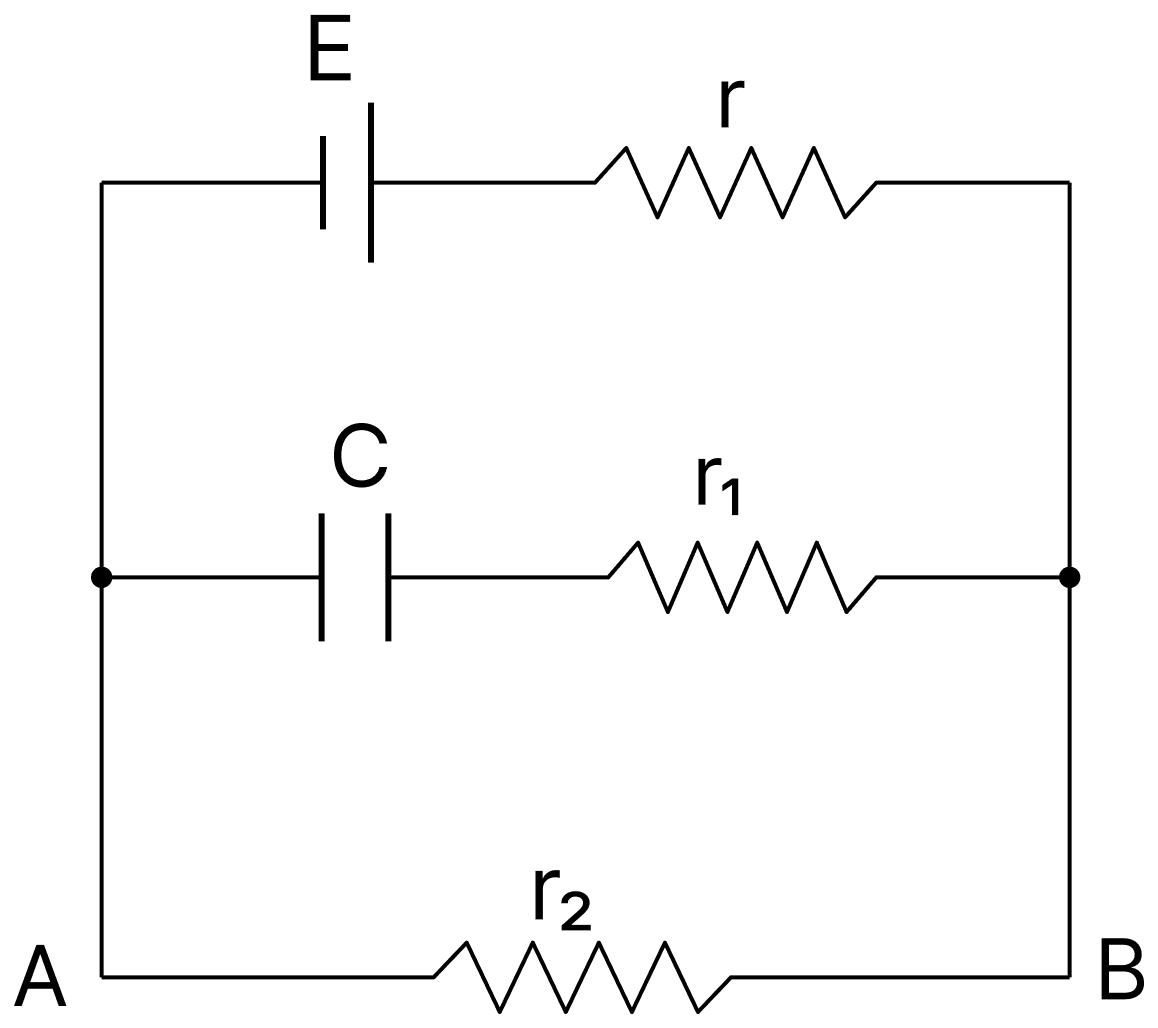
In the given circuit diagram when the current reaches steady state in the circuit, the charge on the capacitor of capacitance C will be:. DC Circuits and Measurements, Nootan Physics Solutions ICS Class 12
  1. CEr1(r1+r)\text{CE} \dfrac{\text r_1}{(\text r_1 + \text r)}
  2. CE
  3. CEr1(r2+r)\text{CE} \dfrac{\text r_1}{(\text r_2 + \text r)}
  4. CEr2(r+r2)\text{CE} \dfrac{\text r_2}{(\text r + \text r_2)}

Answer

CEr2(r+r2)\text{CE} \dfrac{\text r_2}{(\text r + \text r_2)}

Reason — In the steady state no current flows through the branch containing the capacitor, so there is no potential drop across r1. The potential difference across the plates of the capacitor is therefore the same as that between A and B, that is, the potential drop across r2.

The current in the circuit is

I=Er+r2V=Ir2V=Er2r+r2q=CVq=CE r2r+r2\text I = \dfrac{\text E}{\text r + \text r_2} \\[1em] \text V = \text{Ir}_2 \\[1em] \text V = \dfrac{\text{Er}_2}{\text r + \text r_2} \\[1em] \text q = \text{CV} \\[1em] \text q = \text{CE}\ \dfrac{\text r_2}{\text r + \text r_2}

Question 7

Figure shows a circuit that contains three identical resistors with resistance R = 9.0 Ω each, two identical inductors with inductance L = 2.0 mH each, and an ideal battery with emf E = 18 V. The current 'I' through the battery just after the switch closed is :
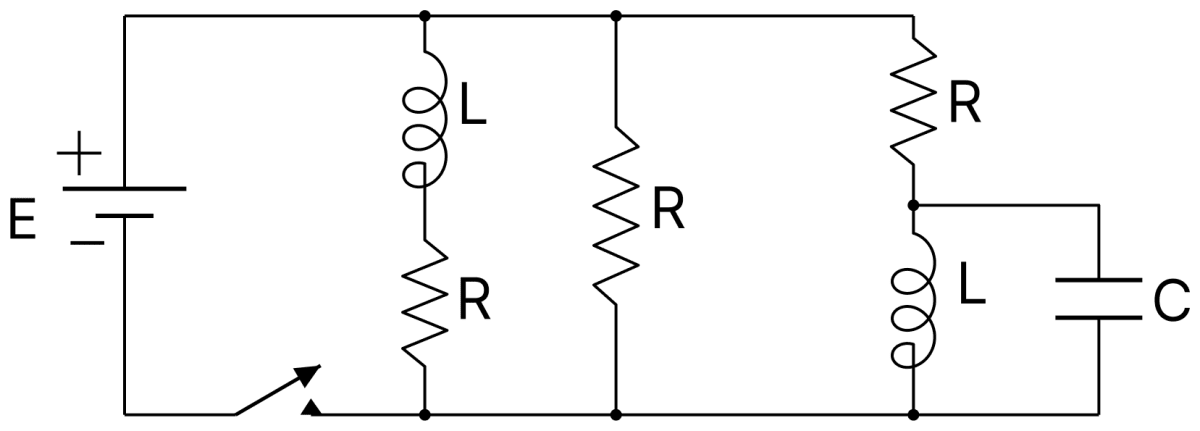
Figure shows a circuit that contains three identical resistors with resistance R = 9.0 Ω each, two identical inductors with inductance L = 2.0 mH each, and an ideal battery with emf E = 18 V. The current I through the battery just after the switch closed is:. DC Circuits and Measurements, Nootan Physics Solutions ICS Class 12
  1. 0.2 A
  2. 2 A
  3. 0 A
  4. 2 mA

Answer

2 A

Reason — The current through an inductor cannot change instantaneously, so just after the switch is closed the current in each inductor is zero. Both the branches containing the inductors therefore carry no current and behave as open branches.

Hence just after the switch is closed the battery drives current only through the single resistor of the middle branch,

I=ERI=189.0I=2 A\text I = \dfrac{\text E}{\text R} \\[1em] \text I = \dfrac{18}{9.0} \\[1em] \text I = 2\ \text A

Question 8

Which of the following statement is false?

  1. Kirchhoff's second law represents energy conservation.
  2. Wheatstone bridge is the most sensitive when all the four resistance are of the same order of magnitude.
  3. In a balanced Wheatstone bridge if the cell and the galvanometer are exchanged, the null-point is disturbed.
  4. A rheostat can be used as a potential divider.

Answer

In a balanced Wheatstone bridge if the cell and the galvanometer are exchanged, the null-point is disturbed.

Reason — The condition of balance of a Wheatstone bridge, P/Q = R/S, involves only the four resistances of the arms. It is therefore unaltered if the cell and the galvanometer are interchanged, and the null-point remains undisturbed. Hence this statement is false.

The other three statements are correct. The loop rule follows from the conservation of energy, the bridge is most sensitive when the four resistances are of the same order of magnitude, and a rheostat connected with its three terminals can indeed be used as a potential divider.

Question 9

A potentiometer is an accurate and versatile device to make electrical measurements of E.M.F. because the method involves :

  1. cells
  2. potential gradients
  3. a condition of no current flow through the galvanometer
  4. a combination of cells, galvanometer and resistances

Answer

a condition of no current flow through the galvanometer

Reason — At the balance point of a potentiometer the galvanometer shows no deflection, so no current is drawn from the cell whose emf is being measured. The cell therefore remains in an open circuit and there is no potential drop across its internal resistance, so the potentiometer measures the true emf and not the terminal potential difference. This null condition is what makes the method accurate.

Question 10

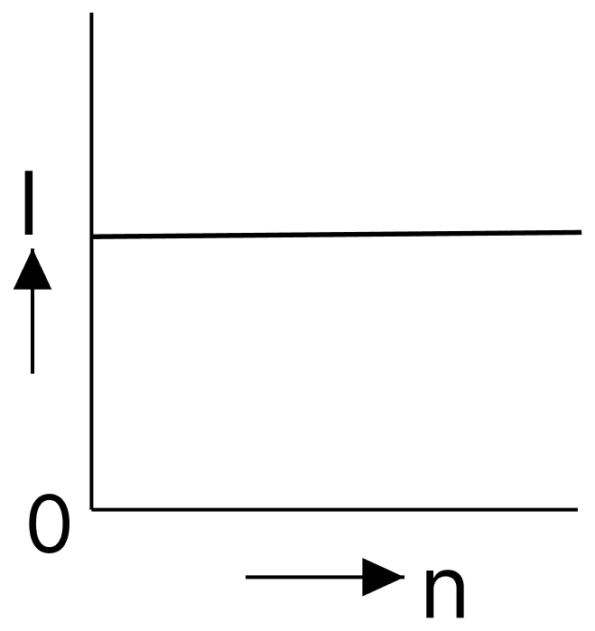
A battery consists of a variable number 'n' of identical cells (having internal resistance 'r' each) which are connected in series. The terminals of the battery are short-circuited and the current I is measured. Which of the graphs shows the correct relationship between I and n?
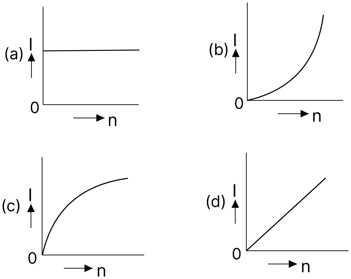
A battery consists of a variable number n of identical cells (having internal resistance r each) which are connected in series. The terminals of the battery are short-circuited and the current I is measured. Which of the graphs shows the correct relationship between I and n? DC Circuits and Measurements, Nootan Physics Solutions ICS Class 12

Answer

A battery consists of a variable number n of identical cells (having internal resistance r each) which are connected in series. The terminals of the battery are short-circuited and the current I is measured. Which of the graphs shows the correct relationship between I and n? DC Circuits and Measurements, Nootan Physics Solutions ICS Class 12

Reason — When n identical cells are joined in series, the net emf is nE and the total internal resistance is nr. On short-circuiting, the external resistance is zero, so

I=nEnrI=Er\text I = \dfrac{\text{nE}}{\text{nr}} \\[1em] \text I = \dfrac{\text E}{\text r}

The current is thus independent of n. The graph of I against n is therefore a straight line parallel to the n-axis, which is shown in option (a).

Question 11

A set of 'n' equal resistors, of value 'R' each, are connected in series to a battery of emf 'E' and internal resistance 'R'. The current drawn is I. Now, the 'n' resistors are connected in parallel to the same battery. Then the current drawn from battery becomes 10 I. The value of 'n' is :

  1. 10
  2. 9
  3. 20
  4. 11

Answer

10

Reason — In the series combination the external resistance is nR, so

I=EnR+R\text I = \dfrac{\text E}{\text{nR} + \text R}

In the parallel combination the external resistance is R/n, so

10 I=ERn+R10\ \text I = \dfrac{\text E}{\dfrac{\text R}{\text n} + \text R}

Dividing the second equation by the first,

10=nR+RRn+R10=(n+1)R(1+n)Rn10=n10 = \dfrac{\text{nR} + \text R}{\dfrac{\text R}{\text n} + \text R} \\[1em] 10 = \dfrac{(\text n + 1)\text R}{\dfrac{(1 + \text n)\text R}{\text n}} \\[1em] 10 = \text n

Hence, n = 10.

Question 12

On interchanging the resistances, the balance point of a metre bridge shifts to the left by 10 cm. The resistance of their series combination is 1 kΩ. How much was the resistance on the left slot before interchanging the resistances?

  1. 550 Ω
  2. 910 Ω
  3. 990 Ω
  4. 505 Ω

Answer

550 Ω

Reason — Let the initial balancing length from the left end be l. On interchanging the two resistances the balance point goes over to (100 − l).

Since this new balance point is 10 cm to the left of the original one,

100−l=l−102 l=110l=55 cm100 - \text l = \text l - 10 \\[1em] 2\ \text l = 110 \\[1em] \text l = 55\ \text{cm}

For the metre bridge,

RS=5545\dfrac{\text R}{\text S} = \dfrac{55}{45}

and it is given that R + S = 1000 Ω. Hence

R=1000×55100R=550 Ω\text R = 1000 \times \dfrac{55}{100} \\[1em] \text R = 550\ \Omega

Question 13

In a potentiometer experiment, it is found that no current passes through the galvanometer when the terminals of the cell are connected across 52 cm of the potentiometer wire. If the cell is shunted by resistance of 5 Ω, a balance is found when the cell is connected across 40 cm of the wire. Find the internal resistance of the cell.

  1. 2 Ω
  2. 2.5 Ω
  3. 1 Ω
  4. 1.5 Ω

Answer

1.5 Ω

Reason — In the potentiometer method for the internal resistance of a cell,

r=R(l1l2−1)\text r = \text R \left(\dfrac{\text l_1}{\text l_2} - 1\right)

Substituting R = 5 Ω, l1 = 52 cm and l2 = 40 cm,

r=5(5240−1)r=5×1240r=1.5 Ω\text r = 5 \left(\dfrac{52}{40} - 1\right) \\[1em] \text r = 5 \times \dfrac{12}{40} \\[1em] \text r = 1.5\ \Omega

Question 14

In the given circuit, the internal resistance of the 18 V cell is negligible. If R1 = 400 Ω, R3 = 100 Ω and R4 = 500 Ω and the reading of an ideal voltmeter across R4 is 5 V, then the value of R2 will be :
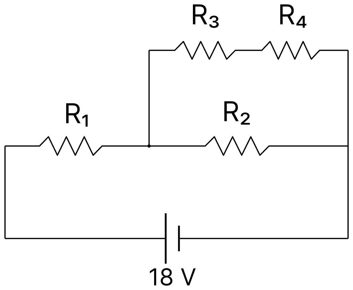
In the given circuit, the internal resistance of the 18 V cell is negligible. If R 1 = 400 Ω, R 3 = 100 Ω and R 4 = 500 Ω and the reading of an ideal voltmeter across R 4 is 5 V, then the value of R 2 will be:. DC Circuits and Measurements, Nootan Physics Solutions ICS Class 12
  1. 550 Ω
  2. 230 Ω
  3. 300 Ω
  4. 450 Ω

Answer

300 Ω

Reason — The current through the branch containing R3 and R4 in series is

I1=5R4I1=5500I1=0.01 A\text I_1 = \dfrac{5}{\text R_4} \\[1em] \text I_1 = \dfrac{5}{500} \\[1em] \text I_1 = 0.01\ \text A

The potential difference across this branch is

V2=I1(R3+R4)V2=0.01×600V2=6 V\text V_2 = \text I_1 (\text R_3 + \text R_4) \\[1em] \text V_2 = 0.01 \times 600 \\[1em] \text V_2 = 6\ \text V

Since R2 is connected in parallel with this branch, the potential difference across R2 is also 6 V.

The remaining potential difference appears across R1,

V1=18−6V1=12 VI=12400I=0.03 A\text V_1 = 18 - 6 \\[1em] \text V_1 = 12\ \text V \\[1em] \text I = \dfrac{12}{400} \\[1em] \text I = 0.03\ \text A

The current through R2 is

I2=0.03−0.01I2=0.02 AR2=60.02R2=300 Ω\text I_2 = 0.03 - 0.01 \\[1em] \text I_2 = 0.02\ \text A \\[1em] \text R_2 = \dfrac{6}{0.02} \\[1em] \text R_2 = 300\ \Omega

Question 15

In the circuit shown, the potential difference between A and B is :
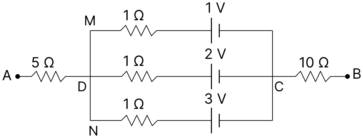
In the circuit shown, the potential difference between A and B is:. DC Circuits and Measurements, Nootan Physics Solutions ICS Class 12
  1. 3 V
  2. 1 V
  3. 6 V
  4. 2 V

Answer

2 V

Reason — A and B are the free ends of the network, so no current is drawn from them. Hence no current flows through the 5 Ω and the 10 Ω resistors and there is no potential drop across either of them.

The three branches, each of 1 Ω with cells of 1 V, 2 V and 3 V, are connected in parallel between the points D and C. The equivalent emf of this parallel combination is

E=11+21+3111+11+11E=63E=2 V\text E = \dfrac{\dfrac{1}{1} + \dfrac{2}{1} + \dfrac{3}{1}}{\dfrac{1}{1} + \dfrac{1}{1} + \dfrac{1}{1}} \\[1em] \text E = \dfrac{6}{3} \\[1em] \text E = 2\ \text V

Since VA = VD and VB = VC, the potential difference between A and B is 2 V.

Question 16

To verify Ohm's law, a student connects the voltmeter across the battery as shown in the figure. The measured voltage is plotted as a function of the current, and the following graph is obtained.
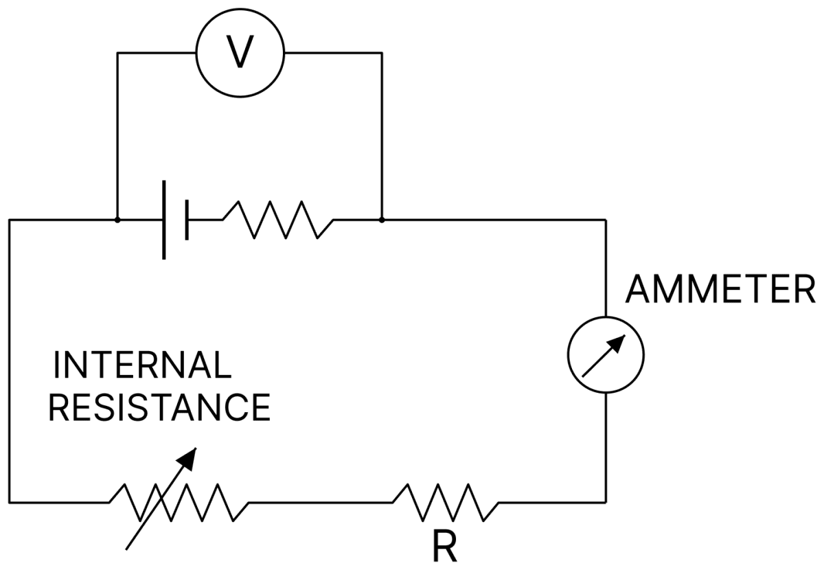
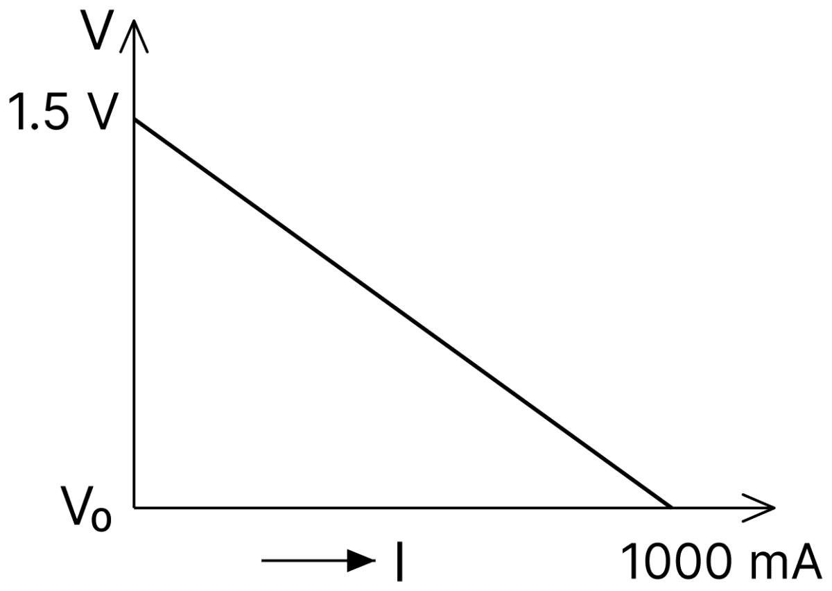
To verify Ohms law, a student connects the voltmeter across the battery as shown in the figure. The measured voltage is plotted as a function of the current, and the following graph is obtained. If V 0 is almost zero, identify the correct statement:. DC Circuits and Measurements, Nootan Physics Solutions ICS Class 12

If V0 is almost zero, identify the correct statement :

  1. The value of the resistance R is 1.5 Ω
  2. The emf of the battery is 1.5 V and its internal resistance is 1.5 Ω
  3. The emf of the battery is 1.5 V and the value of R is 1.5 Ω
  4. The potential difference across the battery is 1.5 V when it sends a current of 1000 mA

Answer

The emf of the battery is 1.5 V and its internal resistance is 1.5 Ω

Reason — The voltmeter is connected across the battery, so it reads the terminal potential difference,

V=E−Ir\text V = \text E - \text{Ir}

The intercept of the graph on the V-axis gives the emf, so E = 1.5 V.

The graph falls to V0 ≈ 0 when the current is 1000 mA = 1 A. Putting V = 0 and I = 1 A,

0=1.5−(1×r)r=1.5 Ω0 = 1.5 - (1 \times \text r) \\[1em] \text r = 1.5\ \Omega

Question 17

When the switch S in the circuit shown is closed, then the value of current I will be :
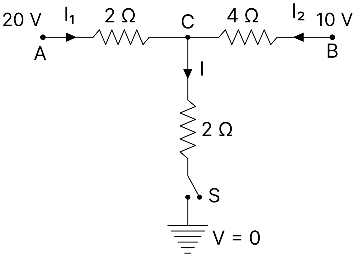
When the switch S in the circuit shown is closed, then the value of current I will be:. DC Circuits and Measurements, Nootan Physics Solutions ICS Class 12
  1. 4 A
  2. 3 A
  3. 2 A
  4. 5 A

Answer

5 A

Reason — Let the potential of the junction C be V, the earthed end being at zero potential. Applying Kirchhoff's junction rule at C,

20−V2+10−V4=V2\dfrac{20 - \text V}{2} + \dfrac{10 - \text V}{4} = \dfrac{\text V}{2}

Multiplying throughout by 4,

2(20−V)+(10−V)=2 V40−2V+10−V=2 V50=5 VV=10 V2(20 - \text V) + (10 - \text V) = 2\ \text V \\[1em] 40 - 2\text V + 10 - \text V = 2\ \text V \\[1em] 50 = 5\ \text V \\[1em] \text V = 10\ \text V

The current through the 2 Ω resistor in the branch containing the switch is

I=V2I=102I=5 A\text I = \dfrac{\text V}{2} \\[1em] \text I = \dfrac{10}{2} \\[1em] \text I = 5\ \text A

Question 18

In the given circuit diagram, the currents I1 = − 0.3 A, I4 = 0.8 A and I5 = 0.4 A, are flowing as shown. The currents I2, I3 and I6 respectively, are :
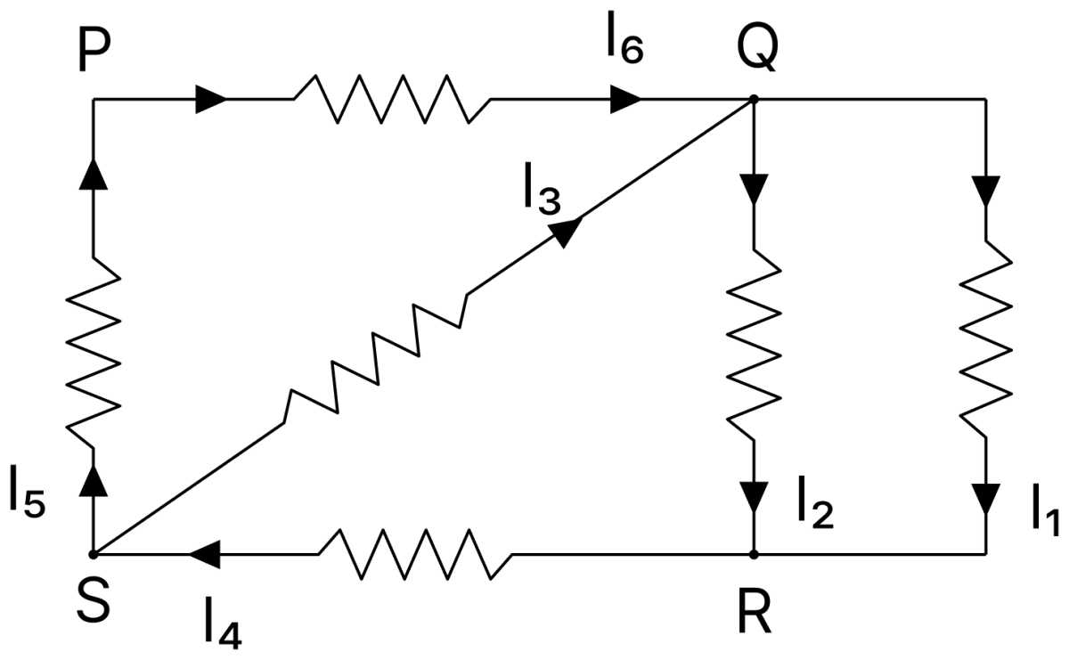
In the given circuit diagram, the currents I 1 = − 0.3 A, I 4 = 0.8 A and I 5 = 0.4 A, are flowing as shown. The currents I 2, I 3 and I 6 respectively, are:. DC Circuits and Measurements, Nootan Physics Solutions ICS Class 12
  1. 1.1 A, 0.4 A, 0.4 A
  2. 1.1 A, − 0.4 A, 0.4 A
  3. 0.4 A, 1.1 A, 0.4 A
  4. 0.4 A, 0.4 A, 1.1 A

Answer

1.1 A, 0.4 A, 0.4 A

Reason — Applying Kirchhoff's junction rule at each junction in turn.

At the junction P : the current I5 arrives and the current I6 leaves,

I6=I5=0.4 A\text I_6 = \text I_5 = 0.4\ \text A

At the junction S : the current I4 arrives while I5 and I3 leave,

I3=I4−I5I3=0.8−0.4I3=0.4 A\text I_3 = \text I_4 - \text I_5 \\[1em] \text I_3 = 0.8 - 0.4 \\[1em] \text I_3 = 0.4\ \text A

At the junction Q : the currents I6 and I3 arrive while I1 and I2 leave,

I6+I3=I1+I20.4+0.4=(−0.3)+I2I2=0.8+0.3I2=1.1 A\text I_6 + \text I_3 = \text I_1 + \text I_2 \\[1em] 0.4 + 0.4 = (-0.3) + \text I_2 \\[1em] \text I_2 = 0.8 + 0.3 \\[1em] \text I_2 = 1.1\ \text A

Question 19

In a meter bridge experiment, the circuit diagram and the corresponding observation table are shown in figure.
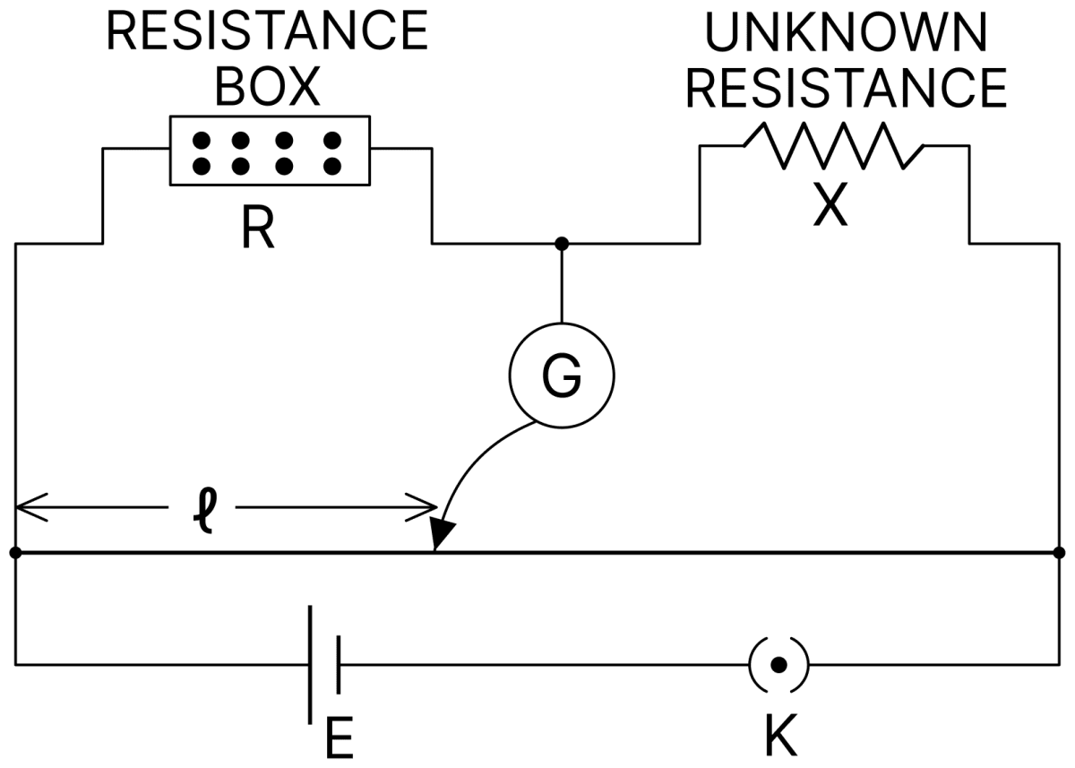
In a meter bridge experiment, the circuit diagram and the corresponding observation table are shown in figure. DC Circuits and Measurements, Nootan Physics Solutions ICS Class 12
S. No.R (Ω)l (cm)
1.100060
2.10013
3.101.5
4.11.0

Which of the reading is inconsistent?

  1. 3
  2. 4
  3. 2
  4. 1

Answer

4

Reason — For the meter bridge the unknown resistance is

X=R (100−l)l\text X = \text R\ \dfrac{(100 - \text l)}{\text l}

Calculating X for each reading,

Reading 1 : X=1000×4060=666.7 Ω\text X = 1000 \times \dfrac{40}{60} = 666.7\ \Omega

Reading 2 : X=100×8713=669.2 Ω\text X = 100 \times \dfrac{87}{13} = 669.2\ \Omega

Reading 3 : X=10×98.51.5=656.7 Ω\text X = 10 \times \dfrac{98.5}{1.5} = 656.7\ \Omega

Reading 4 : X=1×991=99 Ω\text X = 1 \times \dfrac{99}{1} = 99\ \Omega

The first three readings give nearly the same value of X, whereas the fourth gives a value quite different from them. Hence reading 4 is inconsistent.

Question 20

In the experimental set up of meter bridge shown in the figure, the null point is obtained at a distance of 40 cm from A. If a 10 Ω resistor is connected in series with R1, the null point shifts by 10 cm.
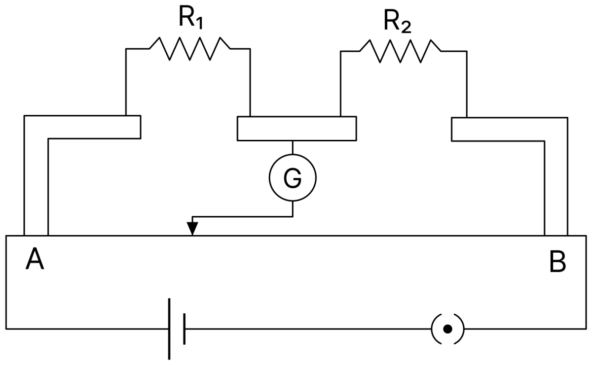
In the experimental set up of meter bridge shown in the figure, the null point is obtained at a distance of 40 cm from A. If a 10 Ω resistor is connected in series with R 1, the null point shifts by 10 cm. The resistance that should be connected in parallel with (R 1 + 10) Ω such that the null point shifts back to its initial position is:. DC Circuits and Measurements, Nootan Physics Solutions ICS Class 12

The resistance that should be connected in parallel with (R1 + 10) Ω such that the null point shifts back to its initial position is :

  1. 60 Ω
  2. 20 Ω
  3. 30 Ω
  4. 40 Ω

Answer

60 Ω

Reason — Initially,

R1R2=4060R1R2=23\dfrac{\text R_1}{\text R_2} = \dfrac{40}{60} \\[1em] \dfrac{\text R_1}{\text R_2} = \dfrac{2}{3}

After adding 10 Ω in series the null point shifts to 50 cm, so

R1+10R2=5050R1+10R2=1R1+10=R2\dfrac{\text R_1 + 10}{\text R_2} = \dfrac{50}{50} \\[1em] \dfrac{\text R_1 + 10}{\text R_2} = 1 \\[1em] \text R_1 + 10 = \text R_2

Substituting R1 = (2/3)R2,

23R2+10=R2R2=30 ΩR1=20 Ω\dfrac{2}{3}\text R_2 + 10 = \text R_2 \\[1em] \text R_2 = 30\ \Omega \\[1em] \text R_1 = 20\ \Omega

To bring the null point back to 40 cm the left gap must again offer 20 Ω. Let X be joined in parallel with 30 Ω,

30 X30+X=2010 X=600X=60 Ω\dfrac{30\ \text X}{30 + \text X} = 20 \\[1em] 10\ \text X = 600 \\[1em] \text X = 60\ \Omega

Question 21

In a meter bridge, the wire of length 1 m has a non-uniform cross-section such that the variation dRdl\dfrac{\text{dR}}{\text{dl}} of its resistance R with length l is dRdl∝1l\dfrac{\text{dR}}{\text{dl}} \propto \dfrac{1}{\sqrt{\text l}}. Two equal resistances are connected as shown in the figure. The galvanometer has zero deflection when the jockey is at point P. What is the length AP?
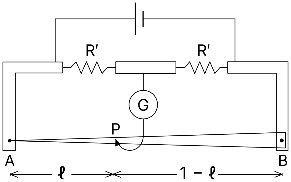
In a meter bridge, the wire of length 1 m has a non-uniform cross-section such that the variation dfracdRdl of its resistance R with length l is dfracdRdl propto dfrac1√( text l). Two equal resistances are connected as shown in the figure. The galvanometer has zero deflection when the jockey is at point P. What is the length AP? DC Circuits and Measurements, Nootan Physics Solutions ICS Class 12
  1. 0.3 m
  2. 0.25 m
  3. 0.2 m
  4. 0.35 m

Answer

0.25 m

Reason — Since

dRdl∝1l\dfrac{\text{dR}}{\text{dl}} \propto \dfrac{1}{\sqrt{\text l}}

let dR/dl = k/√l. Integrating from 0 to l,

R=∫0lkl dlR=k[2l ]0lR=2kl\text R = \int_0^{\text l} \dfrac{\text k}{\sqrt{\text l}}\ \text{dl} \\[1em] \text R = \text k \left[2\sqrt{\text l}\ \right]_0^{\text l} \\[1em] \text R = 2\text k \sqrt{\text l}

Thus the resistance of a portion of the wire is proportional to the square root of its length.

The two resistances in the gaps are equal, so at balance the resistances of the two parts of the wire must also be equal,

RAP=RPB2kl=2k(1−l )2l=1l=0.5l=0.25 m\text R_\text{AP} = \text R_\text{PB} \\[1em] 2\text k \sqrt{\text l} = 2\text k \left(\sqrt{1} - \sqrt{\text l}\ \right) \\[1em] 2\sqrt{\text l} = 1 \\[1em] \sqrt{\text l} = 0.5 \\[1em] \text l = 0.25\ \text m

Question 22

The Wheatstone bridge shown in figure here, gets balanced when the carbon resistor is used as R1 has the colour code (orange, red, brown). The resistors R2 and R4 are 80 Ω and 40 Ω, respectively. Assuming that the colour code for the carbon resistors gives their accurate values, the colour code for the carbon resistor is used as R3 would be :
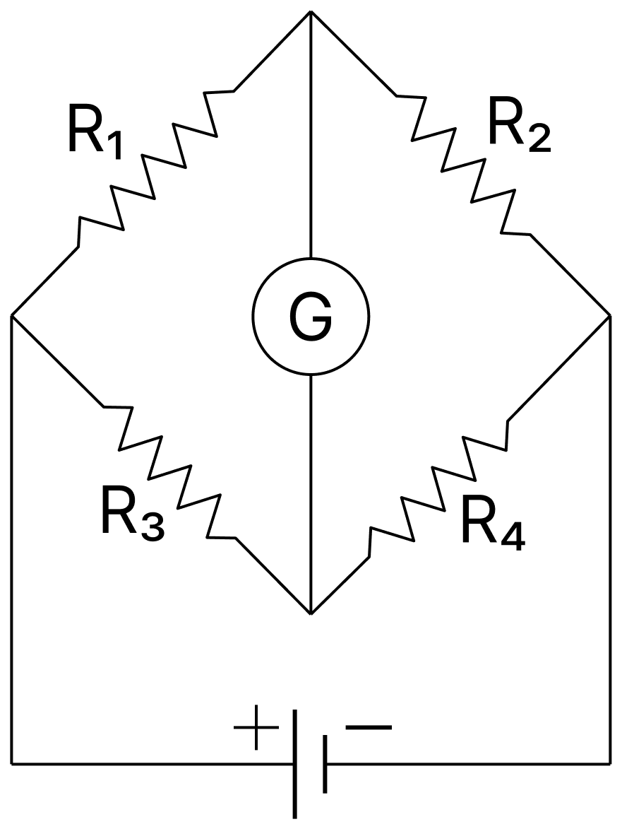
The Wheatstone bridge shown in figure here, gets balanced when the carbon resistor is used as R 1 has the colour code (orange, red, brown). The resistors R 2 and R 4 are 80 Ω and 40 Ω, respectively. Assuming that the colour code for the carbon resistors gives their accurate values, the colour code for the carbon resistor is used as R 3 would be:. DC Circuits and Measurements, Nootan Physics Solutions ICS Class 12
  1. brown, blue, black
  2. brown, blue, brown
  3. grey, black, brown
  4. red, green, brown

Answer

brown, blue, brown

Reason — For the colour code, orange stands for 3, red for 2 and brown for a multiplier of 101. Hence

R1=32×101R1=320 Ω\text R_1 = 32 \times 10^1 \\[1em] \text R_1 = 320\ \Omega

For the balanced bridge,

R1R2=R3R432080=R340R3=4×40R3=160 Ω\dfrac{\text R_1}{\text R_2} = \dfrac{\text R_3}{\text R_4} \\[1em] \dfrac{320}{80} = \dfrac{\text R_3}{40} \\[1em] \text R_3 = 4 \times 40 \\[1em] \text R_3 = 160\ \Omega

Writing 160 Ω as 16 × 101 Ω, the first digit 1 is brown, the second digit 6 is blue and the multiplier 101 is brown.

Question 23

The resistance of the meter bridge AB in given figure is 4 Ω. With a cell of emf E = 0.5 V and rheostat resistance Rh = 2Ω. The null point is obtained at some point J. When the cell is replaced by another one of the emf E = E2, the same null point J is found for Rh = 6Ω. The emf E2 is :
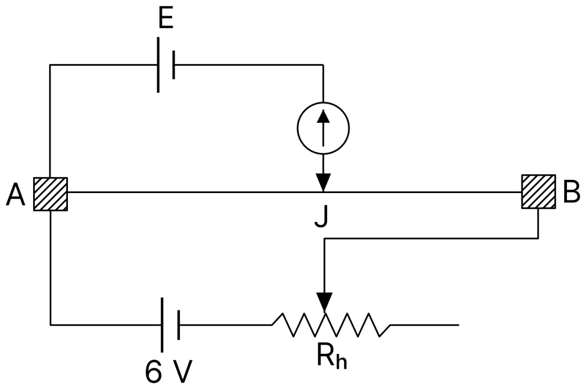
The resistance of the meter bridge AB in given figure is 4 Ω. With a cell of emf E = 0.5 V and rheostat resistance R h = 2Ω. The null point is obtained at some point J. When the cell is replaced by another one of the emf E = E 2, the same null point J is found for R h = 6Ω. The emf E 2 is:. DC Circuits and Measurements, Nootan Physics Solutions ICS Class 12
  1. 0.6 V
  2. 0.3 V
  3. 0.5 V
  4. 0.4 V

Answer

0.3 V

Reason — The primary circuit contains the 6 V cell, the rheostat Rh and the bridge wire AB of resistance 4 Ω.

First case :

I1=62+4I1=1 A\text I_1 = \dfrac{6}{2 + 4} \\[1em] \text I_1 = 1\ \text A

If RAJ is the resistance of the balancing portion,

E=I1 RAJ0.5=1×RAJRAJ=0.5 Ω\text E = \text I_1\ \text R_\text{AJ} \\[1em] 0.5 = 1 \times \text R_\text{AJ} \\[1em] \text R_\text{AJ} = 0.5\ \Omega

Second case : The null point J is the same, so RAJ is unchanged,

I2=66+4I2=0.6 AE2=I2 RAJE2=0.6×0.5E2=0.3 V\text I_2 = \dfrac{6}{6 + 4} \\[1em] \text I_2 = 0.6\ \text A \\[1em] \text E_2 = \text I_2\ \text R_\text{AJ} \\[1em] \text E_2 = 0.6 \times 0.5 \\[1em] \text E_2 = 0.3\ \text V

Question 24

In the circuit, given in the figure currents in different branches and value of one resistor are shown. Then potential at point B with respect to the point A is :
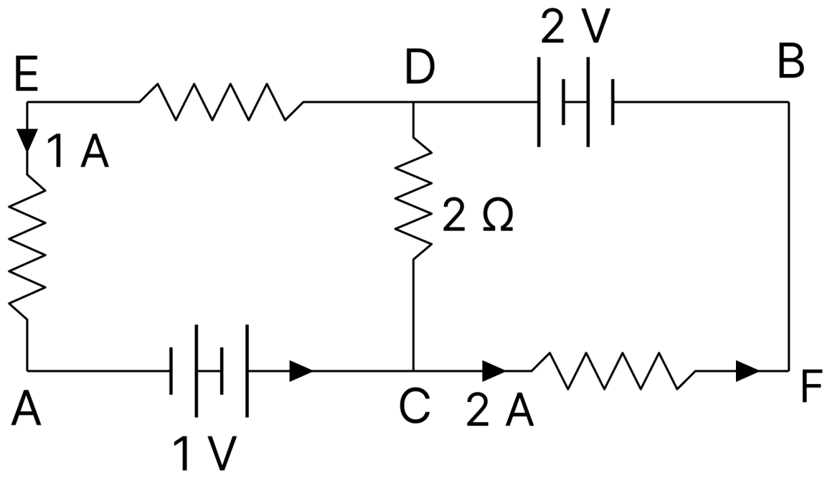
In the circuit, given in the figure currents in different branches and value of one resistor are shown. Then potential at point B with respect to the point A is:. DC Circuits and Measurements, Nootan Physics Solutions ICS Class 12
  1. +1 V
  2. −2 V
  3. +2 V
  4. −1 V

Answer

+1 V

Reason — Take VA = 0.

At the junction D : a current of 2 A arrives and a current of 1 A leaves along the upper branch, so the current flowing from D to C through the 2 Ω resistor is

2−1=1 A2 - 1 = 1\ \text A

Potential at C : going from A to C through the 1 V cell,

VC=0+1VC=1 V\text V_\text C = 0 + 1 \\[1em] \text V_\text C = 1\ \text V

Potential at D : the current of 1 A flows from D to C through the 2 Ω resistor, so

VD=VC+(1×2)VD=3 V\text V_\text D = \text V_\text C + (1 \times 2) \\[1em] \text V_\text D = 3\ \text V

Potential at B : going from B to D through the 2 V cell the potential rises by 2 V,

VB=VD−2VB=3−2VB=1 V\text V_\text B = \text V_\text D - 2 \\[1em] \text V_\text B = 3 - 2 \\[1em] \text V_\text B = 1\ \text V

Hence the potential at B with respect to A is + 1 V.

Question 25

For the circuit given below, the Kirchhoff's loop rule for the loop BCDEB is given by the equation :
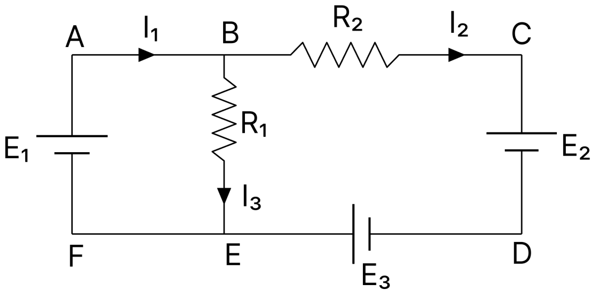
For the circuit given below, the Kirchhoffs loop rule for the loop BCDEB is given by the equation:. DC Circuits and Measurements, Nootan Physics Solutions ICS Class 12
  1. −I2R2 + E2 + E3 + I3R1 = 0
  2. −I2R2 + E2 − E3 + I3R1 = 0
  3. I2R2 + E2 − E3 − I3R1 = 0
  4. I2R2 + E2 + E3 + I3R1 = 0

Answer

I2R2 + E2 − E3 − I3R1 = 0

Reason — The loop BCDEB is traversed in the order B → C → D → E → B.

Going from B to C the loop is traversed in the direction of the current I2 through R2, so the term I2R2 is taken as positive.

Going from C to D through the cell E2 the loop is traversed from its positive to its negative electrode, so E2 is taken as negative.

Going from D to E through the cell E3 the loop is traversed from its negative to its positive electrode, so E3 is taken as positive.

Going from E to B the loop is traversed against the direction of the current I3 through R1, so the term I3R1 is taken as negative.

Applying Kirchhoff's second law (∑IR=∑E\sum \text{IR} = \sum \text E),

I2R2−I3R1=−E2+E3I2R2+E2−E3−I3R1=0\text I_2 \text R_2 - \text I_3 \text R_1 = -\text E_2 + \text E_3 \\[1em] \text I_2 \text R_2 + \text E_2 - \text E_3 - \text I_3 \text R_1 = 0

Question 26

For the circuit shown in the figure, the current I will be :
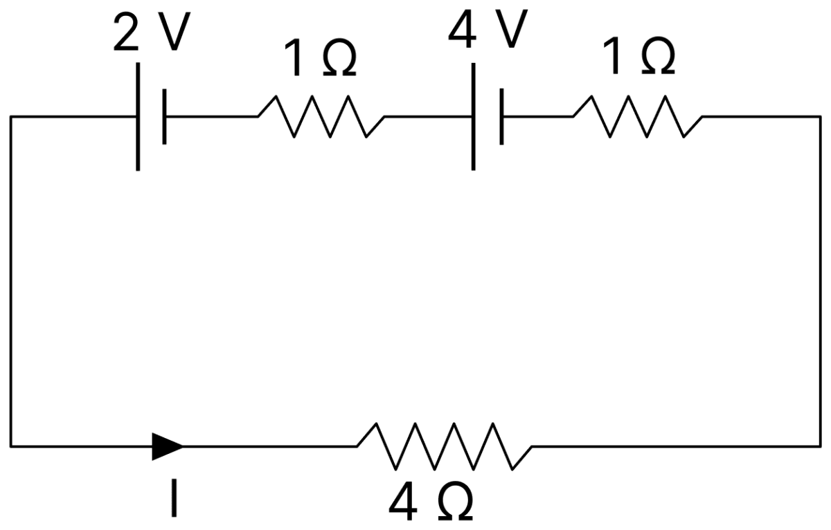
For the circuit shown in the figure, the current I will be:. DC Circuits and Measurements, Nootan Physics Solutions ICS Class 12
  1. 0.5 A
  2. 0.75 A
  3. 1 A
  4. 1.5 A

Answer

1 A

Reason — The two cells of 2 V and 4 V are so connected that their emfs support each other in the loop, so the net emf is

2+4=6 V2 + 4 = 6\ \text V

The resistances in the loop are 1 Ω, 1 Ω and 4 Ω in series,

R=1+1+4R=6 ΩI=66I=1 A\text R = 1 + 1 + 4 \\[1em] \text R = 6\ \Omega \\[1em] \text I = \dfrac{6}{6} \\[1em] \text I = 1\ \text A

Question 27

A potentiometer wire PQ of 1 m length is connected to a standard cell E1. Another cell E2 of emf 1.02 V is connected with a resistance 'r' and switch S (as shown in figure). With switch S open, the null position is obtained at a distance of 49 cm from Q. The potential gradient in the potentiometer wire is :
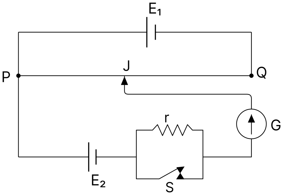
A potentiometer wire PQ of 1 m length is connected to a standard cell E 1. Another cell E 2 of emf 1.02 V is connected with a resistance r and switch S (as shown in figure). With switch S open, the null position is obtained at a distance of 49 cm from Q. The potential gradient in the potentiometer wire is:. DC Circuits and Measurements, Nootan Physics Solutions ICS Class 12
  1. 0.04 V/cm
  2. 0.01 V/cm
  3. 0.02 V/cm
  4. 0.03 V/cm

Answer

0.02 V/cm

Reason — The null position is 49 cm from Q, so the balancing length measured from P is

l=100−49l=51 cm\text l = 100 - 49 \\[1em] \text l = 51\ \text{cm}

With the switch S open no current is drawn from the cell E2, so the balancing length corresponds to its emf,

E2=KlK=E2lK=1.0251K=0.02 V/cm\text E_2 = \text{Kl} \\[1em] \text K = \dfrac{\text E_2}{\text l} \\[1em] \text K = \dfrac{1.02}{51} \\[1em] \text K = 0.02\ \text{V/cm}

Question 28

In a potentiometer circuit a cell of emf 1.5 V gives balance point at 36 cm length of wire. If another cell of emf 2.5 V replaces the first cell, then at what length of the wire, the balance point occurs?

  1. 62 cm
  2. 60 cm
  3. 21.6 cm
  4. 64 cm

Answer

60 cm

Reason — Since the balancing length is proportional to the emf,

E1E2=l1l2l2=l1×E2E1l2=36×2.51.5l2=60 cm\dfrac{\text E_1}{\text E_2} = \dfrac{\text l_1}{\text l_2} \\[1em] \text l_2 = \text l_1 \times \dfrac{\text E_2}{\text E_1} \\[1em] \text l_2 = 36 \times \dfrac{2.5}{1.5} \\[1em] \text l_2 = 60\ \text{cm}

Question 29

In the given figure, there is a circuit of potentiometer of length AB = 10 m. The resistance per unit length is 0.1 Ω per cm. Across AB, a battery of emf E and internal resistance 'r' is connected. The maximum value of emf measured by this potentiometer is :
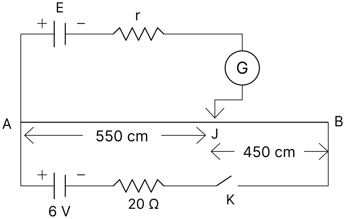
In the given figure, there is a circuit of potentiometer of length AB = 10 m. The resistance per unit length is 0.1 Ω per cm. Across AB, a battery of emf E and internal resistance r is connected. The maximum value of emf measured by this potentiometer is:. DC Circuits and Measurements, Nootan Physics Solutions ICS Class 12
  1. 2.75 V
  2. 2.25 V
  3. 6 V
  4. 5 V

Answer

5 V

Reason — The resistance of the whole potentiometer wire is

RAB=0.1 Ω/cm×1000 cmRAB=100 Ω\text R_\text{AB} = 0.1\ \Omega\text{/cm} \times 1000\ \text{cm} \\[1em] \text R_\text{AB} = 100\ \Omega

The primary circuit contains the 6 V battery and the 20 Ω resistance in series with the wire,

I=620+100I=0.05 A\text I = \dfrac{6}{20 + 100} \\[1em] \text I = 0.05\ \text A

The maximum emf that can be measured is the potential difference across the whole wire,

Vmax=I RABVmax=0.05×100Vmax=5 V\text V_\text{max} = \text I\ \text R_\text{AB} \\[1em] \text V_\text{max} = 0.05 \times 100 \\[1em] \text V_\text{max} = 5\ \text V

Question 30

The given potentiometer has its wire of resistance 10 Ω. When the sliding contact is in the middle of the potentiometer wire, the potential drop across 2Ω resistor is :
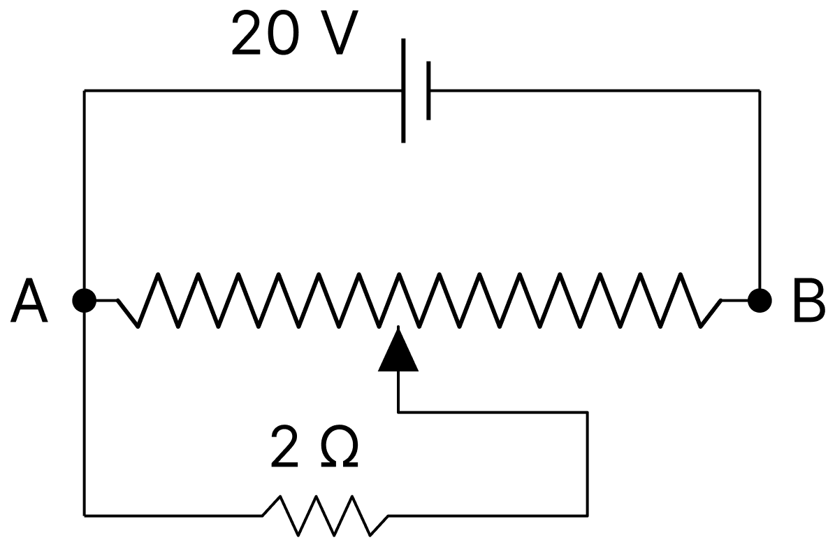
The given potentiometer has its wire of resistance 10 Ω. When the sliding contact is in the middle of the potentiometer wire, the potential drop across 2Ω resistor is:. DC Circuits and Measurements, Nootan Physics Solutions ICS Class 12
  1. 10 V
  2. 4011\dfrac{40}{11} V
  3. 409\dfrac{40}{9} V
  4. 5 V

Answer

409\dfrac{40}{9} V

Reason — The sliding contact is at the middle of the wire, so the wire is divided into two halves of 5 Ω each. The 2 Ω resistor is connected between the sliding contact and the end B, so it is in parallel with the second half,

Rp=5×25+2Rp=107 Ω\text R_\text p = \dfrac{5 \times 2}{5 + 2} \\[1em] \text R_\text p = \dfrac{10}{7}\ \Omega

The total resistance across the 20 V supply is

R=5+107R=457 ΩI=20457I=289 A\text R = 5 + \dfrac{10}{7} \\[1em] \text R = \dfrac{45}{7}\ \Omega \\[1em] \text I = \dfrac{20}{\dfrac{45}{7}} \\[1em] \text I = \dfrac{28}{9}\ \text A

The potential drop across the parallel combination, and hence across the 2 Ω resistor, is

V=I RpV=289×107V=409 V\text V = \text I\ \text R_\text p \\[1em] \text V = \dfrac{28}{9} \times \dfrac{10}{7} \\[1em] \text V = \dfrac{40}{9}\ \text V

Question 31

The four arms of a Wheatstone bridge have resistances as shown in the figure. A galvanometer of 15 Ω resistance is connected across BD. Calculate the current through the galvanometer when a potential difference of 10 V is maintained across AC.
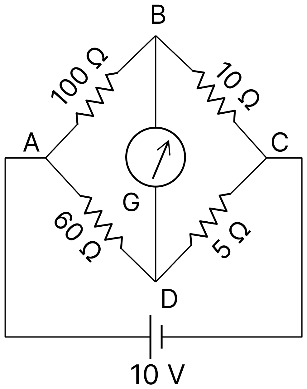
The four arms of a Wheatstone bridge have resistances as shown in the figure. A galvanometer of 15 Ω resistance is connected across BD. Calculate the current through the galvanometer when a potential difference of 10 V is maintained across AC. DC Circuits and Measurements, Nootan Physics Solutions ICS Class 12
  1. 4.87 mA
  2. 4.87 µA
  3. 2.44 mA
  4. 2.44 µA

Answer

4.87 mA

Reason — Testing the condition of balance,

10010=10605=12\dfrac{100}{10} = 10 \\[1em] \dfrac{60}{5} = 12

The bridge is not balanced, so a current flows through the galvanometer.

Potential difference between B and D with the galvanometer removed :

VB−VC=10×10100+10VB−VC=0.909 VVD−VC=10×560+5VD−VC=0.769 VVB−VD=0.909−0.769VB−VD=0.140 V\text V_\text B - \text V_\text C = 10 \times \dfrac{10}{100 + 10} \\[1em] \text V_\text B - \text V_\text C = 0.909\ \text V \\[1em] \text V_\text D - \text V_\text C = 10 \times \dfrac{5}{60 + 5} \\[1em] \text V_\text D - \text V_\text C = 0.769\ \text V \\[1em] \text V_\text B - \text V_\text D = 0.909 - 0.769 \\[1em] \text V_\text B - \text V_\text D = 0.140\ \text V

Resistance of the network between B and D :

100×10110+60×565=9.09+4.62100×10110+60×565=13.71 Ω\dfrac{100 \times 10}{110} + \dfrac{60 \times 5}{65} = 9.09 + 4.62 \\[1em] \dfrac{100 \times 10}{110} + \dfrac{60 \times 5}{65} = 13.71\ \Omega

Current through the galvanometer :

Ig=0.14013.71+15Ig=0.14028.71Ig=4.87×10⁻³ AIg=4.87 mA\text I_\text g = \dfrac{0.140}{13.71 + 15} \\[1em] \text I_\text g = \dfrac{0.140}{28.71} \\[1em] \text I_\text g = 4.87 \times 10^{-3}\ \text A \\[1em] \text I_\text g = 4.87\ \text{mA}

Question 32

The value of current in the 6 Ω resistance is :
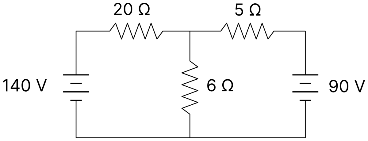
The value of current in the 6 Ω resistance is:. DC Circuits and Measurements, Nootan Physics Solutions ICS Class 12
  1. 4 A
  2. 8 A
  3. 10 A
  4. 6 A

Answer

10 A

Reason — Let V be the potential of the junction to which the 6 Ω resistor is connected, the lower rail being at zero potential. Applying Kirchhoff's junction rule,

140−V20+90−V5=V6\dfrac{140 - \text V}{20} + \dfrac{90 - \text V}{5} = \dfrac{\text V}{6}

Multiplying throughout by 60,

3(140−V)+12(90−V)=10 V420−3V+1080−12V=10 V1500=25 VV=60 V3(140 - \text V) + 12(90 - \text V) = 10\ \text V \\[1em] 420 - 3\text V + 1080 - 12\text V = 10\ \text V \\[1em] 1500 = 25\ \text V \\[1em] \text V = 60\ \text V

The current in the 6 Ω resistance is

I=606I=10 A\text I = \dfrac{60}{6} \\[1em] \text I = 10\ \text A

Question 33

The figure shows a circuit having eight resistances of 1 Ω each, labelled R1 to R8, and two ideal batteries with voltages ε1 = 12 V and ε2 = 6 V.
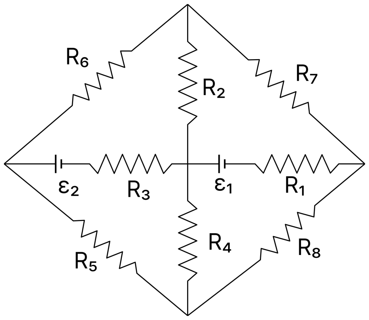
The figure shows a circuit having eight resistances of 1 Ω each, labelled R 1 to R 8, and two ideal batteries with voltages ε 1 = 12 V and ε 2 = 6 V. Which of the following statement(s) is (are) correct? DC Circuits and Measurements, Nootan Physics Solutions ICS Class 12

Which of the following statement(s) is (are) correct?

  1. The magnitude of current flowing through R1 is 7.2 A
  2. The magnitude of current flowing through R2 is 1.2 A
  3. The magnitude of current flowing through R3 is 4.8 A
  4. The magnitude of current flowing through R5 is 2.4 A

Answer

All the four statements are correct.

Reason — Let A be the upper vertex, B the lower vertex, C the left vertex, D the right vertex and O the central junction of the network.

Folding the network : The network is symmetrical about the horizontal line COD, which contains both batteries: R6 is the mirror image of R5, R7 of R8 and R2 of R4. Hence A and B are at the same potential and may be joined into a single point AB. Each mirrored pair of 1 Ω resistances then comes in parallel, giving 12 Ω\dfrac{1}{2}\ \Omega between C and AB, between AB and D, and between AB and O.

Let x be the current in the branch containing ε2 and R3, flowing from O towards C, and y the current in the branch containing ε1 and R1, flowing from O towards D. By Kirchhoff's first law, the current in the 12 Ω\dfrac{1}{2}\ \Omega branch from AB to O is (x + y).

Loop OCABO (through ε2) : Traversed in the direction of x, the cell ε2 is crossed from its negative to its positive electrode. Applying Kirchhoff's second law (∑IR=∑E\sum \text{IR} = \sum \text E),

1×x+12x+12(x+y)=62x+y2=64x+y=12...(i)1 \times x + \dfrac{1}{2}x + \dfrac{1}{2}(x + y) = 6 \\[1em] 2x + \dfrac{y}{2} = 6 \\[1em] 4x + y = 12 \qquad ...(i)

Loop ODABO (through ε1) : Traversed in the direction of y, the cell ε1 is crossed from its positive to its negative electrode,

1×y+12y+12(x+y)=−12x2+2y=−12x+4y=−24...(ii)1 \times y + \dfrac{1}{2}y + \dfrac{1}{2}(x + y) = -12 \\[1em] \dfrac{x}{2} + 2y = -12 \\[1em] x + 4y = -24 \qquad ...(ii)

Multiplying Eq. (i) by 4 and subtracting Eq. (ii),

15x=48+2415x=72x=4.8 A15x = 48 + 24 \\[1em] 15x = 72 \\[1em] x = 4.8\ \text A

From Eq. (i),

y=12−(4×4.8)y=−7.2 Ay = 12 - (4 \times 4.8) \\[1em] y = -7.2\ \text A

The negative sign shows only that the current in the R1 branch flows from D to O. The current (x + y) = −2.4 A divides equally between R2 and R4, and the current x divides equally between R6 and R5,

∣I1∣=∣y∣∣I1∣=7.2 A∣I3∣=x∣I3∣=4.8 A∣I2∣=∣x+y∣2∣I2∣=2.42∣I2∣=1.2 A∣I5∣=x2∣I5∣=4.82∣I5∣=2.4 A|\text I_1| = |y| \\[1em] |\text I_1| = 7.2\ \text A \\[1em] |\text I_3| = x \\[1em] |\text I_3| = 4.8\ \text A \\[1em] |\text I_2| = \dfrac{|x + y|}{2} \\[1em] |\text I_2| = \dfrac{2.4}{2} \\[1em] |\text I_2| = 1.2\ \text A \\[1em] |\text I_5| = \dfrac{x}{2} \\[1em] |\text I_5| = \dfrac{4.8}{2} \\[1em] |\text I_5| = 2.4\ \text A

Each of the four statements therefore agrees with the calculated value, and all of them are correct.

Question 34

A Wheatstone bridge is used to determine the value of unknown resistance X by adjusting the variable resistance Y as shown in the figure. For the most precise measurement of X, the resistances P and Q :
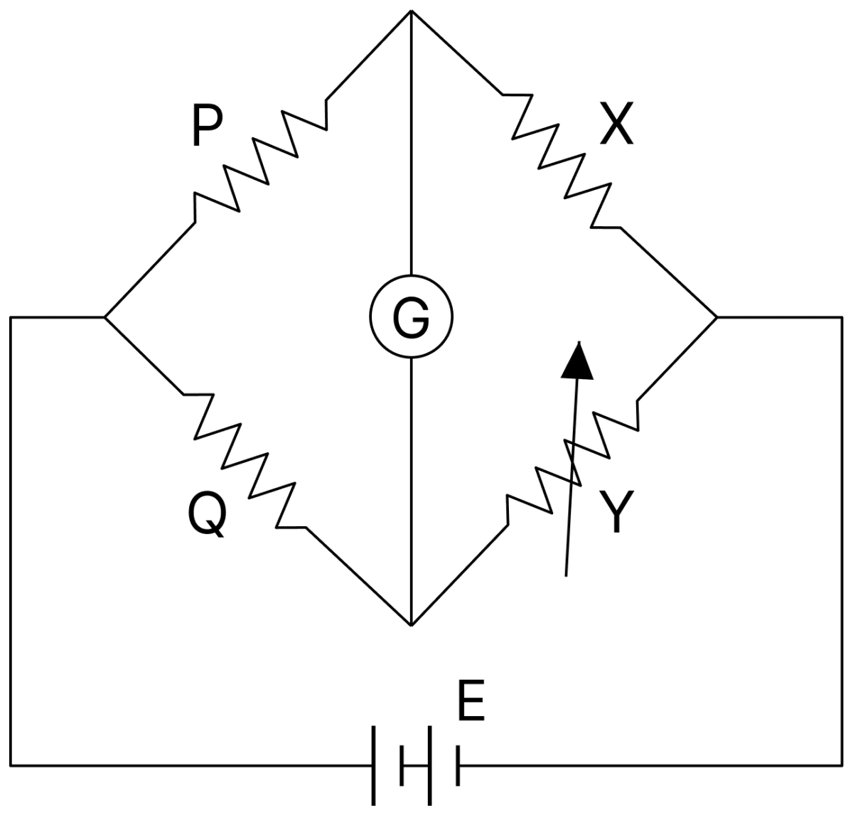
A Wheatstone bridge is used to determine the value of unknown resistance X by adjusting the variable resistance Y as shown in the figure. For the most precise measurement of X, the resistances P and Q:. DC Circuits and Measurements, Nootan Physics Solutions ICS Class 12
  1. do not play any significant role
  2. should be approximately equal to 2X
  3. should be approximately equal and are small
  4. should be very large and unequal

Answer

should be approximately equal and are small

Reason — A Wheatstone bridge is most sensitive when all the four resistances of its arms are of the same order of magnitude. If P and Q are approximately equal, the ratio arms are balanced and a small change in X produces the largest change in the galvanometer deflection.

Keeping P and Q small also allows a larger current to flow through the bridge, which makes the galvanometer deflection more pronounced and the detection of the null point more precise.

Question 35

Figure shows a part of an electric circuit. The potentials at points a, b and c are 30 V, 12 V and 2 V respectively. The current through the 20 Ω resistor will be :
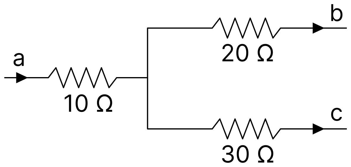
Figure shows a part of an electric circuit. The potentials at points a, b and c are 30 V, 12 V and 2 V respectively. The current through the 20 Ω resistor will be:. DC Circuits and Measurements, Nootan Physics Solutions ICS Class 12
  1. 0.2 A
  2. 1.0 A
  3. 0.6 A
  4. 0.4 A

Answer

0.4 A

Reason — Let V be the potential of the junction where the three resistors meet. Applying Kirchhoff's junction rule,

30−V10=V−1220+V−230\dfrac{30 - \text V}{10} = \dfrac{\text V - 12}{20} + \dfrac{\text V - 2}{30}

Multiplying throughout by 60,

6(30−V)=3(V−12)+2(V−2)180−6V=3V−36+2V−4220=11 VV=20 V6(30 - \text V) = 3(\text V - 12) + 2(\text V - 2) \\[1em] 180 - 6\text V = 3\text V - 36 + 2\text V - 4 \\[1em] 220 = 11\ \text V \\[1em] \text V = 20\ \text V

The current through the 20 Ω resistor is

I=V−1220I=20−1220I=0.4 A\text I = \dfrac{\text V - 12}{20} \\[1em] \text I = \dfrac{20 - 12}{20} \\[1em] \text I = 0.4\ \text A

Question 36

In this figure, the resistance of the coil of galvanometer G is 2 Ω. The emf of the cell is 4 V. The ratio of potential difference across C1 and C2 is :
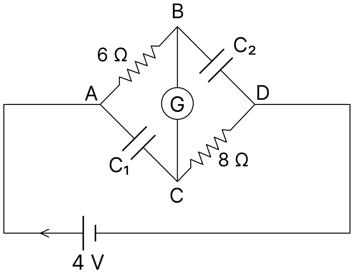
In this figure, the resistance of the coil of galvanometer G is 2 Ω. The emf of the cell is 4 V. The ratio of potential difference across C 1 and C 2 is:. DC Circuits and Measurements, Nootan Physics Solutions ICS Class 12
  1. 45\dfrac{4}{5}
  2. 1
  3. 54\dfrac{5}{4}
  4. 34\dfrac{3}{4}

Answer

45\dfrac{4}{5}

Reason — In the steady state no current flows through the branches containing the capacitors. Hence the whole current flows along the path containing the 6 Ω resistor, the galvanometer of 2 Ω and the 8 Ω resistor in series,

I=46+2+8I=416I=0.25 A\text I = \dfrac{4}{6 + 2 + 8} \\[1em] \text I = \dfrac{4}{16} \\[1em] \text I = 0.25\ \text A

The potential difference across C1 is that between A and C,

V1=(0.25×6)+(0.25×2)V1=1.5+0.5V1=2 V\text V_1 = (0.25 \times 6) + (0.25 \times 2) \\[1em] \text V_1 = 1.5 + 0.5 \\[1em] \text V_1 = 2\ \text V

The potential difference across C2 is that between B and D,

V2=(0.25×2)+(0.25×8)V2=0.5+2V2=2.5 VV1V2=22.5V1V2=45\text V_2 = (0.25 \times 2) + (0.25 \times 8) \\[1em] \text V_2 = 0.5 + 2 \\[1em] \text V_2 = 2.5\ \text V \\[1em] \dfrac{\text V_1}{\text V_2} = \dfrac{2}{2.5} \\[1em] \dfrac{\text V_1}{\text V_2} = \dfrac{4}{5}

Question 37

10 resistors, each of resistance R are connected in series to a battery of emf E and negligible internal resistance. Then those are connected in parallel to the same battery, the current is increased n times. The value of n is :

  1. 1
  2. 1000
  3. 10
  4. 100

Answer

100

Reason — With the ten resistors in series the external resistance is 10R, so

Is=E10 R\text I_\text s = \dfrac{\text E}{10\ \text R}

With them in parallel the external resistance is R/10, so

Ip=ER10Ip=10 ERn=IpIsn=10 ERE10 Rn=100\text I_\text p = \dfrac{\text E}{\dfrac{\text R}{10}} \\[1em] \text I_\text p = \dfrac{10\ \text E}{\text R} \\[1em] \text n = \dfrac{\text I_\text p}{\text I_\text s} \\[1em] \text n = \dfrac{\dfrac{10\ \text E}{\text R}}{\dfrac{\text E}{10\ \text R}} \\[1em] \text n = 100

Question 38

In a circuit shown in the figure, the capacitor C is initially uncharged and the key K is open. In this condition, a current of 1 A flows through the 1 Ω resistor. The key is closed at time t = t0. Which of the following statements is (are) corret?

[Given : e-1 = 0.36]
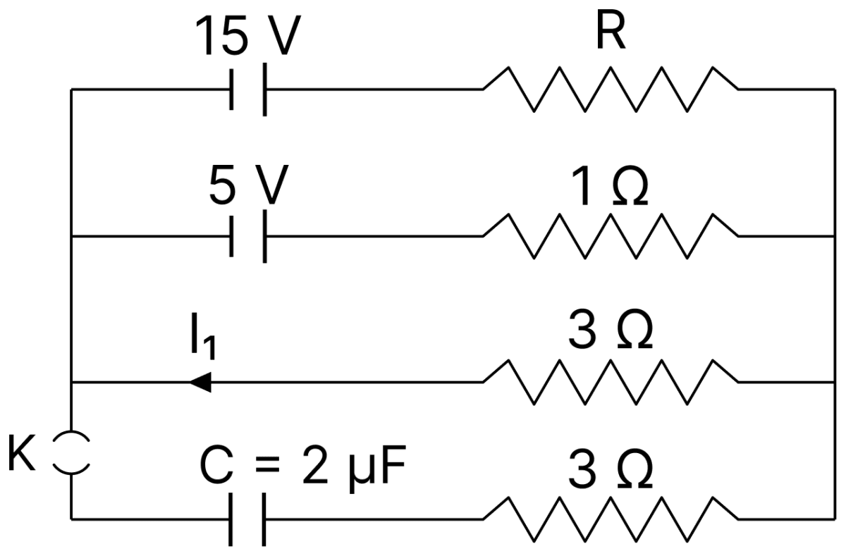
In a circuit shown in the figure, the capacitor C is initially uncharged and the key K is open. In this condition, a current of 1 A flows through the 1 Ω resistor. The key is closed at time t = t 0. Which of the following statements is (are) corret? [Given: e -1 = 0.36]. DC Circuits and Measurements, Nootan Physics Solutions ICS Class 12
  1. The value of the resistance R is 3 Ω.
  2. For t < t0, the value of current I1 is 2 A.
  3. At t = t0 + 7.2 µs, the current in the capacitor is 0.6 A.
  4. For t → ∞, the charge on the capacitor is 12 µC.

Answer

All the four statements are correct.

Reason — Let L be the left junction and N the right junction joining the four branches. Both cells have their positive electrodes towards N.

Before the key is closed : The capacitor branch carries no current. The current of 1 A in the 1 Ω resistor flows from N to L, so going from L to N along this branch,

VN−VL=5+(1×1)VN−VL=6 V\text V_\text N - \text V_\text L = 5 + (1 \times 1) \\[1em] \text V_\text N - \text V_\text L = 6\ \text V

The same potential difference drives the current I1 through the 3 Ω branch,

I1×3=6I1=2 A\text I_1 \times 3 = 6 \\[1em] \text I_1 = 2\ \text A

By Kirchhoff's first law at L, the current in the branch containing R is I = I1 + 1 = 3 A, flowing from L to N. For this branch,

15−IR=615−3R=6R=3 Ω15 - \text{IR} = 6 \\[1em] 15 - 3\text R = 6 \\[1em] \text R = 3\ \Omega

After the key is closed : The three branches without the capacitor act as one equivalent cell,

1req=13+11+13req=35 ΩEeq=req(153+51+03)Eeq=35×10Eeq=6 V\dfrac{1}{\text r_\text{eq}} = \dfrac{1}{3} + \dfrac{1}{1} + \dfrac{1}{3} \\[1em] \text r_\text{eq} = \dfrac{3}{5}\ \Omega \\[1em] \text E_\text{eq} = \text r_\text{eq}\left(\dfrac{15}{3} + \dfrac{5}{1} + \dfrac{0}{3}\right) \\[1em] \text E_\text{eq} = \dfrac{3}{5} \times 10 \\[1em] \text E_\text{eq} = 6\ \text V

The capacitor charges through req and the 3 Ω resistor in series, so the time constant is

CR=(2×10−6)×(35+3)CR=7.2×10⁻⁶ s\text{CR} = (2 \times 10^{-6}) \times \left(\dfrac{3}{5} + 3\right) \\[1em] \text{CR} = 7.2 \times 10^{-6}\ \text s

The charging current is I=Eeqreq+3 e−(t−t0)/CR\text I = \dfrac{\text E_\text{eq}}{\text r_\text{eq} + 3}\ \text e^{-(\text t - \text t_0)/\text{CR}}. At t = t0 + 7.2 µs, (t − t0) = CR,

I=63.6×e−1I=53×0.36I=0.6 A\text I = \dfrac{6}{3.6} \times \text e^{-1} \\[1em] \text I = \dfrac{5}{3} \times 0.36 \\[1em] \text I = 0.6\ \text A

As t → ∞ no current flows in the capacitor branch, and the potential difference across the capacitor equals Eeq = 6 V,

Q=CVQ=2 μF×6 VQ=12 μC\text Q = \text{CV} \\[1em] \text Q = 2\ \mu\text F \times 6\ \text V \\[1em] \text Q = 12\ \mu\text C

Each of the four statements therefore agrees with the calculated value, and all of them are correct.

Question 39

A wire of length 10 cm and radius 7×10⁻⁴\sqrt{7} \times 10^{-4} m connected across the right gap of a meter bridge. When a resistance of 4.5 Ω is connected on the left gap by using a resistance box, the balance length is found to be at 60 cm from the left end. If the resistivity of the wire is R × 10-7 Ωm, then value of R is :

  1. 63
  2. 70
  3. 66
  4. 35

Answer

66

Reason — For the meter bridge,

4.5S=60404.5S=1.5S=4.51.5S=3 Ω\dfrac{4.5}{\text S} = \dfrac{60}{40} \\[1em] \dfrac{4.5}{\text S} = 1.5 \\[1em] \text S = \dfrac{4.5}{1.5} \\[1em] \text S = 3\ \Omega

The area of cross-section of the wire is

A=πr2A=227×(7×10−4)2A=227×7×10−8A=22×10−8 m2\text A = \pi \text r^2 \\[1em] \text A = \dfrac{22}{7} \times (\sqrt{7} \times 10^{-4})^2 \\[1em] \text A = \dfrac{22}{7} \times 7 \times 10^{-8} \\[1em] \text A = 22 \times 10^{-8}\ \text m^2

The resistivity is

ρ=SAlρ=3×22×10−80.10ρ=66×10−7 Ω m\rho = \dfrac{\text{SA}}{\text l} \\[1em] \rho = \dfrac{3 \times 22 \times 10^{-8}}{0.10} \\[1em] \rho = 66 \times 10^{-7}\ \Omega\ \text m

Comparing with ρ = R × 10-7 Ω m, we get R = 66.

Question 40

The terminal voltage of the battery, whose emf is 10V and internal resistance 1Ω when connected through an external resistance of 4 Ω (as shown in the figure) is:
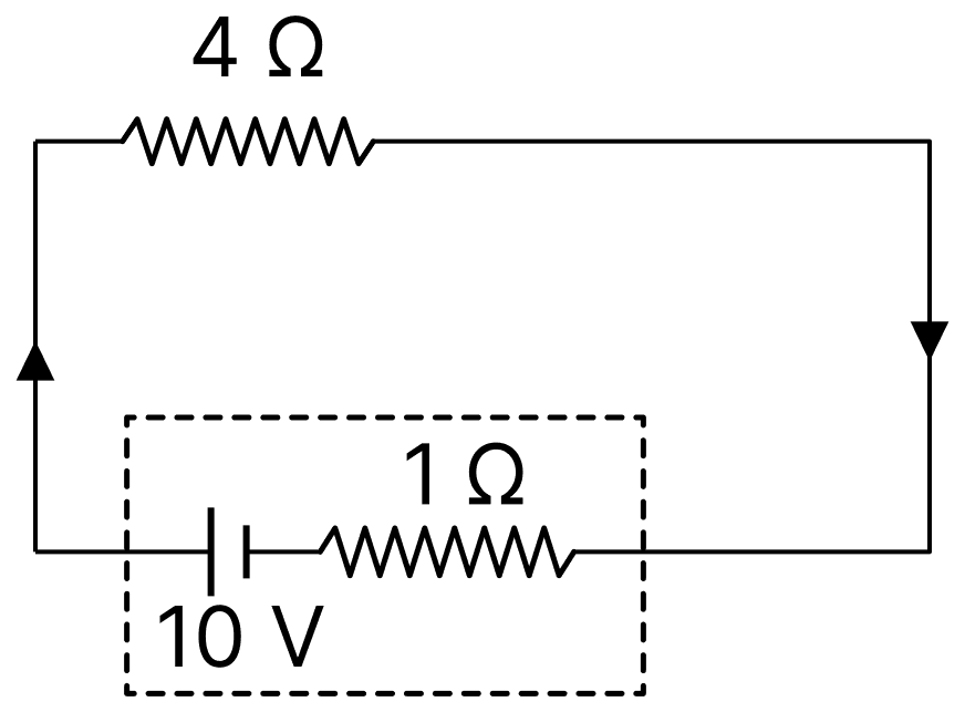
The terminal voltage of the battery, whose emf is 10V and internal resistance 1&Omega; when connected through an external resistance of 4 &Omega; (as shown in the figure) is:. DC Circuits and Measurements, Nootan Physics Solutions ICS Class 12
  1. 4V
  2. 6V
  3. 8V
  4. 10V

Answer

8V

Reason — The current in the circuit is

I=ER+rI=104+1I=2 A\text I = \dfrac{\text E}{\text R + \text r} \\[1em] \text I = \dfrac{10}{4 + 1} \\[1em] \text I = 2\ \text A

The terminal voltage is

V=E−IrV=10−(2×1)V=8 V\text V = \text E - \text{Ir} \\[1em] \text V = 10 - (2 \times 1) \\[1em] \text V = 8\ \text V

Competition Zone — Numerical Value Type Questions

Question 1

An ideal cell of emf 10 V is connected in circuit shown in figure. Each resistance is 2Ω. The potential difference (in V) across the capacitor when it is fully charged is ............... .
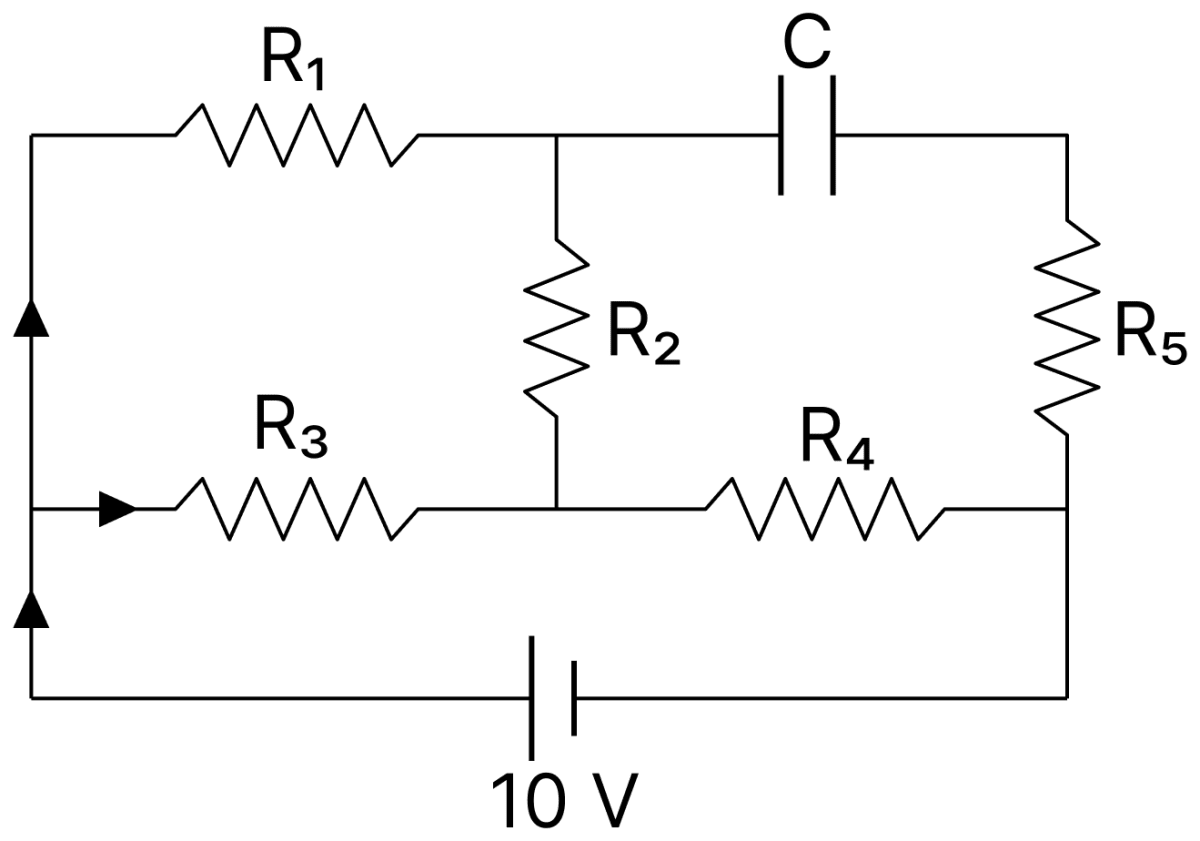
An ideal cell of emf 10 V is connected in circuit shown in figure. Each resistance is 2&Omega;. The potential difference (in V) across the capacitor when it is fully charged is................ DC Circuits and Measurements, Nootan Physics Solutions ICS Class 12

Answer

Given,

  • Emf of the ideal cell, E = 10 V
  • Each resistance R1 = R2 = R3 = R4 = R5 = 2 Ω

When the capacitor is fully charged, no current flows in the branch containing the capacitor, and hence no current flows through R5 which lies in that branch.

The current therefore flows from the cell along two paths from A to the junction M, namely through R3 alone and through R1 and R2 in series, and then through R4 back to the cell.

R1+R2=2+2R1+R2=4 ΩRAM=2×42+4RAM=86RAM=43 ΩR=43+2R=103 ΩI=10103I=3 A\text R_1 + \text R_2 = 2 + 2 \\[1em] \text R_1 + \text R_2 = 4\ \Omega \\[1em] \text R_\text{AM} = \dfrac{2 \times 4}{2 + 4} \\[1em] \text R_\text{AM} = \dfrac{8}{6} \\[1em] \text R_\text{AM} = \dfrac{4}{3}\ \Omega \\[1em] \text R = \dfrac{4}{3} + 2 \\[1em] \text R = \dfrac{10}{3}\ \Omega \\[1em] \text I = \dfrac{10}{\dfrac{10}{3}} \\[1em] \text I = 3\ \text A

The potential difference between A and M is

VAM=3×43VAM=4 V\text V_\text{AM} = 3 \times \dfrac{4}{3} \\[1em] \text V_\text{AM} = 4\ \text V

The current in the branch containing R1 and R2 is

44=1 A\dfrac{4}{4} = 1\ \text A

Taking the negative terminal of the cell as zero potential, VA = 10 V. The potential of the junction Q between R1 and the capacitor is

VQ=10−(1×2)VQ=8 V\text V_\text Q = 10 - (1 \times 2) \\[1em] \text V_\text Q = 8\ \text V

Since no current flows through R5, the other plate of the capacitor is at the potential of the negative terminal, that is, at 0 V.

VC=8−0VC=8 V\text V_\text C = 8 - 0 \\[1em] \text V_\text C = 8\ \text V

Hence, the potential difference across the capacitor is 8 V.

Question 2

First, a set of a n equal resistor of 10 Ω each are connected in series to a battery of emf 20 V and internal resistance 10 Ω. A current I is observed to flow. Then, the n resistors are connected in parallel to the same battery. It is observed that the current is increased 20 times, then the value of n is ............... .

Answer

Given,

  • Each resistor = 10 Ω, number of resistors = n
  • Emf of the battery, E = 20 V, internal resistance r = 10 Ω
  • Current in parallel = 20 × current in series

In series,

I=2010 n+10\text I = \dfrac{20}{10\ \text n + 10}

In parallel,

20 I=2010n+1020\ \text I = \dfrac{20}{\dfrac{10}{\text n} + 10}

Dividing the second equation by the first,

20=10 n+1010n+1020(10n+10)=10 n+10200n+200=10 n+1020 = \dfrac{10\ \text n + 10}{\dfrac{10}{\text n} + 10} \\[1em] 20\left(\dfrac{10}{\text n} + 10\right) = 10\ \text n + 10 \\[1em] \dfrac{200}{\text n} + 200 = 10\ \text n + 10

Multiplying throughout by n,

200+200 n=10 n2+10 n10 n2−190 n−200=0n2−19 n−20=0(n−20)(n+1)=0200 + 200\ \text n = 10\ \text n^2 + 10\ \text n \\[1em] 10\ \text n^2 - 190\ \text n - 200 = 0 \\[1em] \text n^2 - 19\ \text n - 20 = 0 \\[1em] (\text n - 20)(\text n + 1) = 0

Since n cannot be negative, n = 20.

Hence, the value of n is 20.

Question 3

A capacitor of 50 µF is connected in a circuit as shown in figure. The charge on the upper plate of the capacitor is ............... µC.
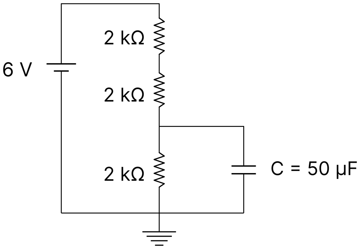
A capacitor of 50 &micro;F is connected in a circuit as shown in figure. The charge on the upper plate of the capacitor is............... &micro;C. DC Circuits and Measurements, Nootan Physics Solutions ICS Class 12

Answer

Given,

  • C = 50 µF
  • Three resistors of 2 kΩ each in series across a 6 V supply
  • The capacitor is connected across the lowest 2 kΩ resistor

In the steady state no current flows through the capacitor branch, so the current flows through the three resistors in series,

I=63×2000I=66000I=1×10⁻³ A\text I = \dfrac{6}{3 \times 2000} \\[1em] \text I = \dfrac{6}{6000} \\[1em] \text I = 1 \times 10^{-3}\ \text A

The potential difference across the lowest 2 kΩ resistor, and hence across the capacitor, is

V=(1×10−3)×2000V=2 Vq=CVq=50×2q=100 μC\text V = (1 \times 10^{-3}) \times 2000 \\[1em] \text V = 2\ \text V \\[1em] \text q = \text{CV} \\[1em] \text q = 50 \times 2 \\[1em] \text q = 100\ \mu\text C

Hence, the charge on the upper plate of the capacitor is 100 µC.

Question 4

The voltage drop across 15 Ω resistance in the given figure will be ............... V.
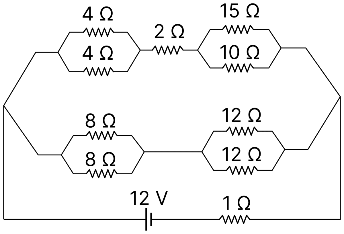
The voltage drop across 15 &Omega; resistance in the given figure will be............... V. DC Circuits and Measurements, Nootan Physics Solutions ICS Class 12

Answer

Given,

  • Emf of the cell = 12 V with a 1 Ω resistor in series
  • Upper path : 4 Ω ∥ 4 Ω, then 2 Ω, then 15 Ω ∥ 10 Ω
  • Lower path : 8 Ω ∥ 8 Ω, then 12 Ω ∥ 12 Ω

Upper path :

4×48=2 Ω15×1025=6 ΩRupper=2+2+6Rupper=10 Ω\dfrac{4 \times 4}{8} = 2\ \Omega \\[1em] \dfrac{15 \times 10}{25} = 6\ \Omega \\[1em] \text R_\text{upper} = 2 + 2 + 6 \\[1em] \text R_\text{upper} = 10\ \Omega

Lower path :

8×816=4 Ω12×1224=6 ΩRlower=4+6Rlower=10 Ω\dfrac{8 \times 8}{16} = 4\ \Omega \\[1em] \dfrac{12 \times 12}{24} = 6\ \Omega \\[1em] \text R_\text{lower} = 4 + 6 \\[1em] \text R_\text{lower} = 10\ \Omega

The two paths are in parallel,

Rp=10×1020Rp=5 ΩI=125+1I=2 A\text R_\text p = \dfrac{10 \times 10}{20} \\[1em] \text R_\text p = 5\ \Omega \\[1em] \text I = \dfrac{12}{5 + 1} \\[1em] \text I = 2\ \text A

Since the two paths have equal resistance, the current divides equally and 1 A flows through the upper path. The voltage drop across the parallel combination of 15 Ω and 10 Ω is

V=1×6V=6 V\text V = 1 \times 6 \\[1em] \text V = 6\ \text V

Hence, the voltage drop across the 15 Ω resistance is 6 V.

Question 5

In an electric circuit, a cell of certain emf provides a potential difference of 1.25 V across a load resistance of 5 Ω. However, it provides a potential difference of 1 V across a load resistance of 2 Ω. The emf of the cell is given by x10\dfrac{\text x}{10} V. Then the value of x is ............... .

Answer

Given,

  • V1 = 1.25 V across R1 = 5 Ω
  • V2 = 1 V across R2 = 2 Ω

First case :

I1=1.255I1=0.25 AE=1.25+0.25 r...(i)\text I_1 = \dfrac{1.25}{5} \\[1em] \text I_1 = 0.25\ \text A \\[1em] \text E = 1.25 + 0.25\ \text r \qquad ...(i)

Second case :

I2=12I2=0.5 AE=1+0.5 r...(ii)\text I_2 = \dfrac{1}{2} \\[1em] \text I_2 = 0.5\ \text A \\[1em] \text E = 1 + 0.5\ \text r \qquad ...(ii)

Equating Eqs. (i) and (ii),

1.25+0.25 r=1+0.5 r0.25=0.25 rr=1 ΩE=1.25+(0.25×1)E=1.5 VE=1510 V1.25 + 0.25\ \text r = 1 + 0.5\ \text r \\[1em] 0.25 = 0.25\ \text r \\[1em] \text r = 1\ \Omega \\[1em] \text E = 1.25 + (0.25 \times 1) \\[1em] \text E = 1.5\ \text V \\[1em] \text E = \dfrac{15}{10}\ \text V

Hence, the value of x is 15.

Question 6

A 16 Ω wire is bend to form a square loop. A 9 V supply having internal resistance of 1 Ω is connected across one of its sides. The potential drop across the diagonals of the square loop is ............... × 10-1 V.

Answer

Given,

  • Resistance of the whole wire = 16 Ω
  • Emf of the supply = 9 V, internal resistance = 1 Ω

Each side of the square has a resistance of

164=4 Ω\dfrac{16}{4} = 4\ \Omega

The supply is connected across one side AB, so this side of 4 Ω is in parallel with the other three sides in series, that is, with 12 Ω,

R=4×124+12R=3 ΩI=93+1I=2.25 A\text R = \dfrac{4 \times 12}{4 + 12} \\[1em] \text R = 3\ \Omega \\[1em] \text I = \dfrac{9}{3 + 1} \\[1em] \text I = 2.25\ \text A

The potential difference across AB is

VAB=2.25×3VAB=6.75 V\text V_\text{AB} = 2.25 \times 3 \\[1em] \text V_\text{AB} = 6.75\ \text V

The current in the path A–D–C–B of 12 Ω is

6.7512=0.5625 A\dfrac{6.75}{12} = 0.5625\ \text A

Taking VB = 0 so that VA = 6.75 V, the potential drop across each of the sides AD and DC is

0.5625×4=2.25 VVD=6.75−2.25VD=4.5 VVC=4.5−2.25VC=2.25 V0.5625 \times 4 = 2.25\ \text V \\[1em] \text V_\text D = 6.75 - 2.25 \\[1em] \text V_\text D = 4.5\ \text V \\[1em] \text V_\text C = 4.5 - 2.25 \\[1em] \text V_\text C = 2.25\ \text V

The potential drop across the diagonal AC is

VA−VC=6.75−2.25VA−VC=4.5 VVA−VC=45×10−1 V\text V_\text A - \text V_\text C = 6.75 - 2.25 \\[1em] \text V_\text A - \text V_\text C = 4.5\ \text V \\[1em] \text V_\text A - \text V_\text C = 45 \times 10^{-1}\ \text V

Hence, the required value is 45.

Question 7

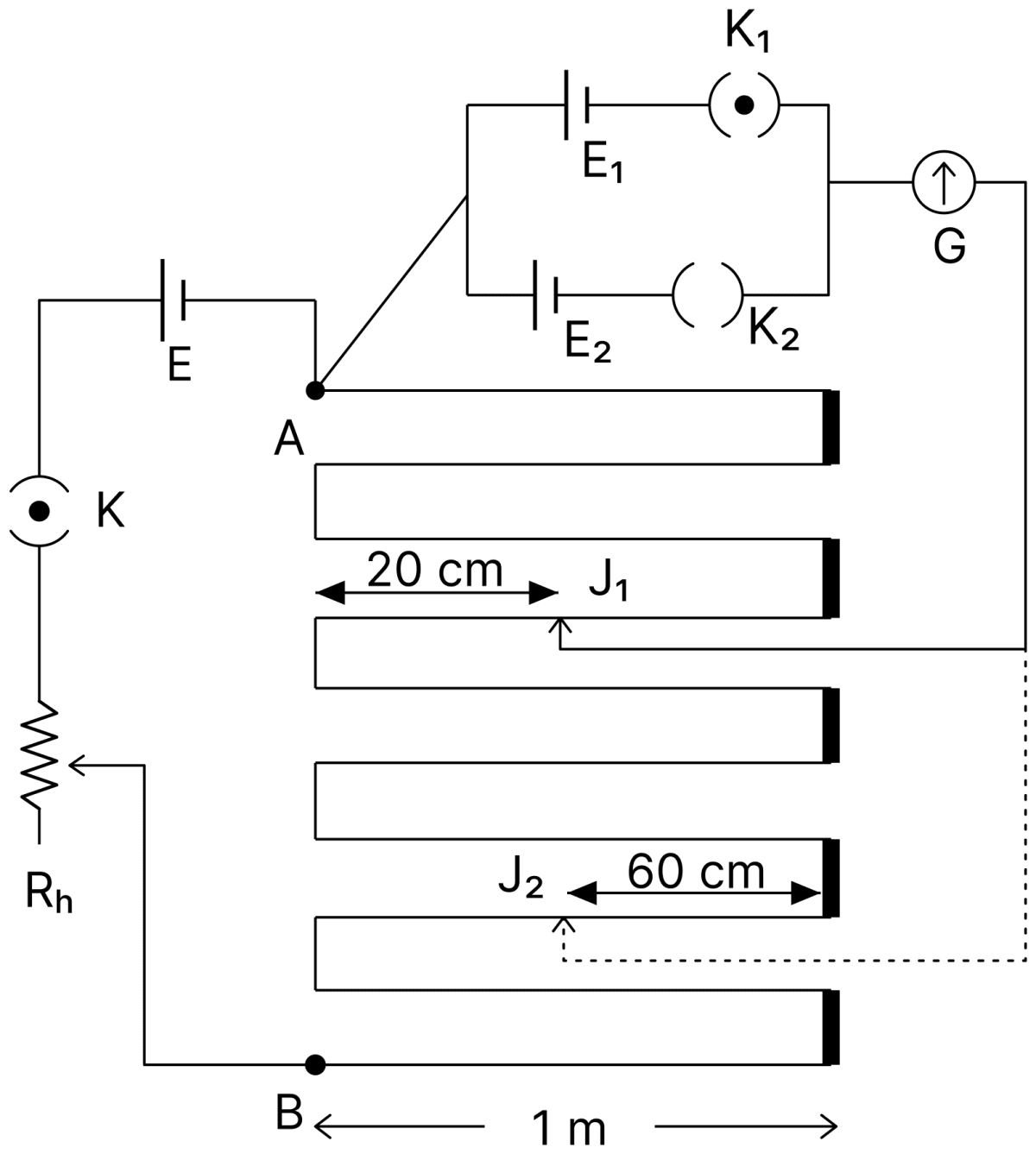
In the given circuit of potentiometer, the potential difference E across AB (10 m length) is larger than E1 and E2 as well. For key K1 (closed), the jockey is adjusted to touch the wire at point J1, so that there is no deflection in the galvanometer. Now, the first battery (E1) is replaced by second battery (E2) for working by making K1 open and K2 closed. The galvanometer gives then null deflection at J2. The value of E1E2\dfrac{\text E_1}{\text E_2} is ab\dfrac{\text a}{\text b}, where a = ............... .

In the given circuit of potentiometer, the potential difference E across AB (10 m length) is larger than E 1 and E 2 as well. For key K 1 (closed), the jockey is adjusted to touch the wire at point J 1, so that there is no deflection in the galvanometer. Now, the first battery (E 1 ) is replaced by second battery (E 2 ) for working by making K 1 open and K 2 closed. The galvanometer gives then null deflection at J 2. The value of text E_1/ text E_2 is text a/ text b, where a =................ DC Circuits and Measurements, Nootan Physics Solutions ICS Class 12

Answer

Given,

  • Balancing length for E1, l1 = 20 cm
  • Balancing length for E2, l2 = 60 cm

Since the emf is proportional to the balancing length,

E1E2=l1l2E1E2=2060E1E2=13\dfrac{\text E_1}{\text E_2} = \dfrac{\text l_1}{\text l_2} \\[1em] \dfrac{\text E_1}{\text E_2} = \dfrac{20}{60} \\[1em] \dfrac{\text E_1}{\text E_2} = \dfrac{1}{3}

Comparing with a/b, we get a = 1 and b = 3.

Hence, the value of a is 1.

Question 8

In the given figure, the value of V0 will be ............... V.
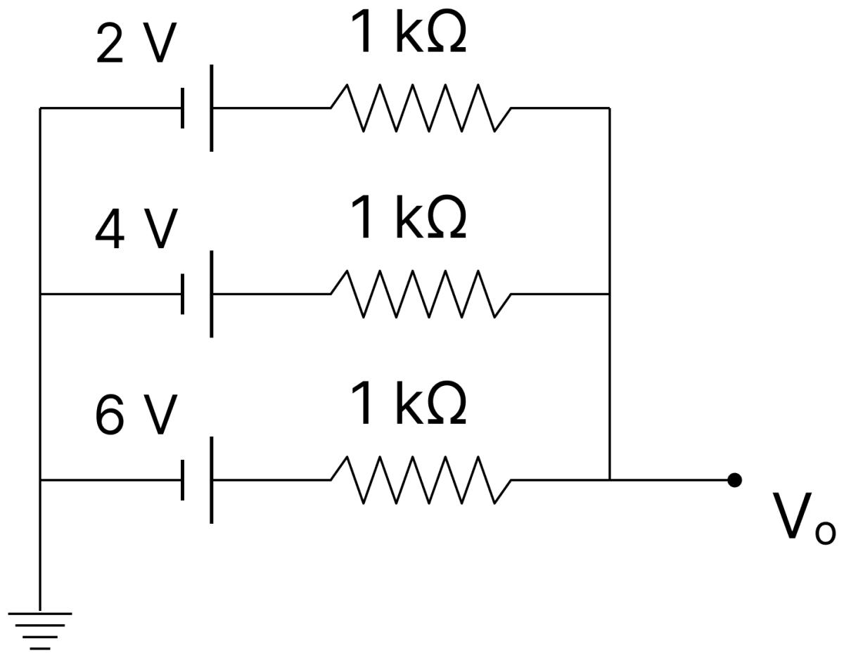
In the given figure, the value of V 0 will be............... V. DC Circuits and Measurements, Nootan Physics Solutions ICS Class 12

Answer

Given,

  • Three branches, each of 1 kΩ, containing cells of 2 V, 4 V and 6 V, joined in parallel

Since no current is drawn at the output terminal, the three branches form a parallel combination of cells. The emf of the equivalent cell is

V0=E1R1+E2R2+E3R31R1+1R2+1R3\text V_0 = \dfrac{\dfrac{\text E_1}{\text R_1} + \dfrac{\text E_2}{\text R_2} + \dfrac{\text E_3}{\text R_3}}{\dfrac{1}{\text R_1} + \dfrac{1}{\text R_2} + \dfrac{1}{\text R_3}}

All the three resistances are equal, so

V0=2+4+63V0=123V0=4 V\text V_0 = \dfrac{2 + 4 + 6}{3} \\[1em] \text V_0 = \dfrac{12}{3} \\[1em] \text V_0 = 4\ \text V

Hence, the value of V0 is 4 V.

Question 9

As shown in the figure, in steady state, the charge stored in the capacitor is ............... × 10-6 C.
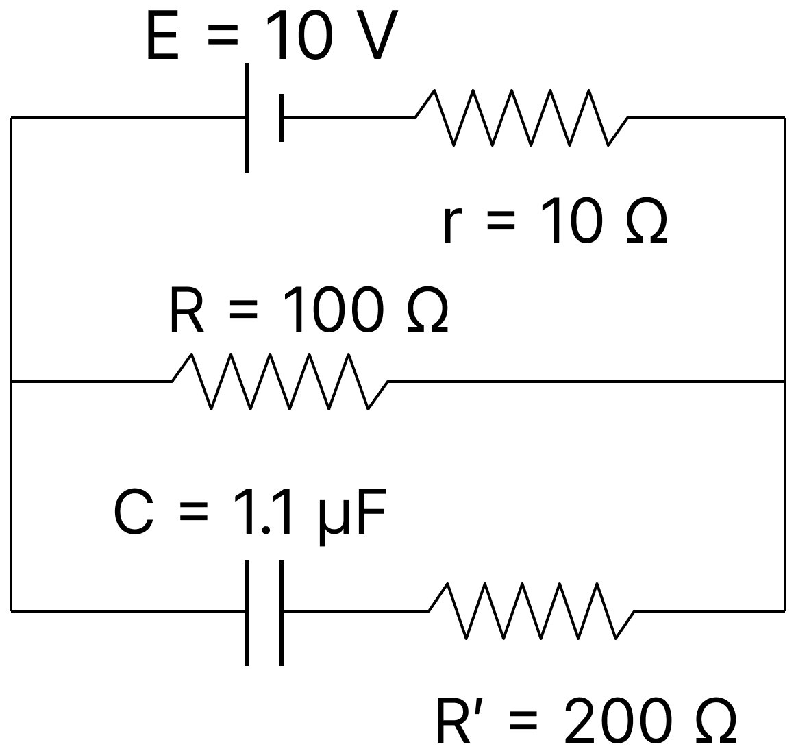
As shown in the figure, in steady state, the charge stored in the capacitor is............... &times; 10 -6 C. DC Circuits and Measurements, Nootan Physics Solutions ICS Class 12

Answer

Given,

  • E = 10 V, r = 10 Ω
  • R = 100 Ω, R' = 200 Ω
  • C = 1.1 µF

In the steady state no current flows in the branch containing the capacitor, so no current flows through R' and there is no potential drop across it.

The current in the circuit is

I=Er+RI=1010+100I=111 A\text I = \dfrac{\text E}{\text r + \text R} \\[1em] \text I = \dfrac{10}{10 + 100} \\[1em] \text I = \dfrac{1}{11}\ \text A

The potential difference across R, and hence across the capacitor, is

V=IRV=111×100V=10011 Vq=CVq=(1.1×10−6)×10011q=10×10−6 C\text V = \text{IR} \\[1em] \text V = \dfrac{1}{11} \times 100 \\[1em] \text V = \dfrac{100}{11}\ \text V \\[1em] \text q = \text{CV} \\[1em] \text q = (1.1 \times 10^{-6}) \times \dfrac{100}{11} \\[1em] \text q = 10 \times 10^{-6}\ \text C

Hence, the charge stored in the capacitor is 10 × 10-6 C.

Question 10

For the network shown in the figure, the value of VB − VA is ............... V.
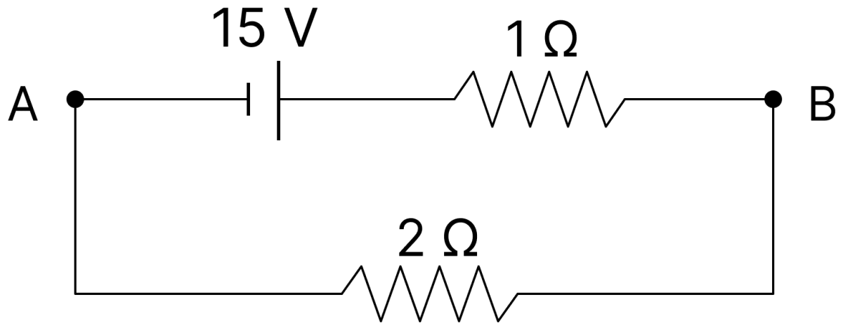
For the network shown in the figure, the value of V B &minus; V A is............... V. DC Circuits and Measurements, Nootan Physics Solutions ICS Class 12

Answer

Given,

  • Cell of 15 V with a 1 Ω resistor in the branch AB
  • A 2 Ω resistor in the other branch between A and B

The two branches form a closed loop, so the current in the loop is

I=151+2I=5 A\text I = \dfrac{15}{1 + 2} \\[1em] \text I = 5\ \text A

The potential difference between B and A is the potential drop across the 2 Ω resistor,

VB−VA=I×2VB−VA=5×2VB−VA=10 V\text V_\text B - \text V_\text A = \text I \times 2 \\[1em] \text V_\text B - \text V_\text A = 5 \times 2 \\[1em] \text V_\text B - \text V_\text A = 10\ \text V

Hence, VB − VA = 10 V.

Question 11

Resistance are connected in a meter bridge circuit as shown in the figure. The balancing length l1 is 40 cm. Now an unknown resistance x is connected in series with P and new balancing length is found to be 80 cm measured from the same end. Then the value of x will be ............... Ω.
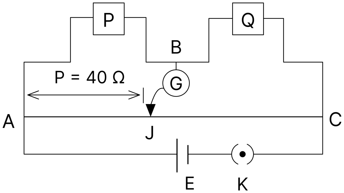
Resistance are connected in a meter bridge circuit as shown in the figure. The balancing length l 1 is 40 cm. Now an unknown resistance x is connected in series with P and new balancing length is found to be 80 cm measured from the same end. Then the value of x will be............... &Omega;. DC Circuits and Measurements, Nootan Physics Solutions ICS Class 12

Answer

Given,

  • P = 40 Ω in the left gap
  • Initial balancing length, l1 = 40 cm
  • New balancing length, l2 = 80 cm

Initially,

PQ=l1100−l1PQ=4060PQ=23Q=32×40Q=60 Ω\dfrac{\text P}{\text Q} = \dfrac{\text l_1}{100 - \text l_1} \\[1em] \dfrac{\text P}{\text Q} = \dfrac{40}{60} \\[1em] \dfrac{\text P}{\text Q} = \dfrac{2}{3} \\[1em] \text Q = \dfrac{3}{2} \times 40 \\[1em] \text Q = 60\ \Omega

After connecting x in series with P,

P+xQ=l2100−l2P+xQ=8020P+xQ=4P+x=4×60P+x=240 Ωx=240−40x=200 Ω\dfrac{\text P + \text x}{\text Q} = \dfrac{\text l_2}{100 - \text l_2} \\[1em] \dfrac{\text P + \text x}{\text Q} = \dfrac{80}{20} \\[1em] \dfrac{\text P + \text x}{\text Q} = 4 \\[1em] \text P + \text x = 4 \times 60 \\[1em] \text P + \text x = 240\ \Omega \\[1em] \text x = 240 - 40 \\[1em] \text x = 200\ \Omega

Hence, the value of x is 200 Ω.

Note: The printed answer key gives 20 for this question, which is the same value as that printed for the next question. The balancing conditions for the two positions of the null point lead to x = 200 Ω, so the key appears to be in error here.

Question 12

A potentiometer wire of length 300 cm is connected in series with a resistance 780 Ω and a standard cell of emf 4 V. A constant current flows through potentiometer wire. The length of the null point for cell of emf 20 mV is found to be 60 cm. The resistance of the potentiometer wire is ............... Ω.

Answer

Given,

  • Length of the wire, L = 300 cm
  • Series resistance = 780 Ω, emf of the standard cell = 4 V
  • Emf of the cell in the secondary circuit = 20 mV = 20 × 10-3 V at l = 60 cm

The potential gradient along the wire is

K=20×10−360 V/cm\text K = \dfrac{20 \times 10^{-3}}{60}\ \text{V/cm}

The potential difference across the whole wire is

V=KLV=20×10−360×300V=0.1 V\text V = \text{KL} \\[1em] \text V = \dfrac{20 \times 10^{-3}}{60} \times 300 \\[1em] \text V = 0.1\ \text V

If R is the resistance of the potentiometer wire, the current in the primary circuit is

I=4780+RV=IR0.1=4 R780+R78+0.1 R=4 R3.9 R=78R=20 Ω\text I = \dfrac{4}{780 + \text R} \\[1em] \text V = \text{IR} \\[1em] 0.1 = \dfrac{4\ \text R}{780 + \text R} \\[1em] 78 + 0.1\ \text R = 4\ \text R \\[1em] 3.9\ \text R = 78 \\[1em] \text R = 20\ \Omega

Hence, the resistance of the potentiometer wire is 20 Ω.

Question 13

In a meter bridge experiment, for measuring unknown resistance S, the null point is obtained at a distance 30 cm from the left side as shown at point D. If R is 5.6 kΩ, then the value of unknown resistance S will be ............... Ω.
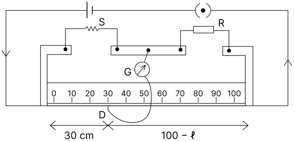
In a meter bridge experiment, for measuring unknown resistance S, the null point is obtained at a distance 30 cm from the left side as shown at point D. If R is 5.6 k&Omega;, then the value of unknown resistance S will be............... &Omega;. DC Circuits and Measurements, Nootan Physics Solutions ICS Class 12

Answer

Given,

  • R = 5.6 kΩ = 5600 Ω
  • Balancing length from the left end, l = 30 cm

The unknown resistance S is in the left gap, so

SR=l100−lSR=3070S=5600×3070S=5600×37S=2400 Ω\dfrac{\text S}{\text R} = \dfrac{\text l}{100 - \text l} \\[1em] \dfrac{\text S}{\text R} = \dfrac{30}{70} \\[1em] \text S = 5600 \times \dfrac{30}{70} \\[1em] \text S = 5600 \times \dfrac{3}{7} \\[1em] \text S = 2400\ \Omega

Hence, the value of the unknown resistance S is 2400 Ω.

Question 14

In a potentiometer arrangement, a cell gives a balancing point at 75 cm length of wire. This cell is now replaced by another cell of unknown emf. If the ratio of the emfs of two cells respectively is 3 : 2, the difference in the balancing length of the potentiometer wire in above two cases will be ............... cm.

Answer

Given,

  • l1 = 75 cm
  • E1 : E2 = 3 : 2

Since the balancing length is proportional to the emf,

E1E2=l1l2E1E2=32l2=23×75l2=50 cm\dfrac{\text E_1}{\text E_2} = \dfrac{\text l_1}{\text l_2} \\[1em] \dfrac{\text E_1}{\text E_2} = \dfrac{3}{2} \\[1em] \text l_2 = \dfrac{2}{3} \times 75 \\[1em] \text l_2 = 50\ \text{cm}

The difference in the balancing lengths is

l1−l2=75−50l1−l2=25 cm\text l_1 - \text l_2 = 75 - 50 \\[1em] \text l_1 - \text l_2 = 25\ \text{cm}

Hence, the difference in the balancing length is 25 cm.

Question 15

A cell, shunted by a 8 Ω resistance, is balanced across a potentiometer wire of length 3 m. The balancing length is 2 m, when the cell is shunted by 4 Ω resistance. The value of internal resistance of the cell will be ............... Ω.

Answer

Given,

  • R1 = 8 Ω, l1 = 3 m
  • R2 = 4 Ω, l2 = 2 m

When the cell of emf E and internal resistance r is shunted by a resistance R, the terminal potential difference is

V=ERR+r\text V = \dfrac{\text{ER}}{\text R + \text r}

Since the balancing length is proportional to this potential difference,

l1l2=ER1R1+rER2R2+rl1l2=R1(R2+r)R2(R1+r)32=8(4+r)4(8+r)32=2(4+r)8+r3(8+r)=4(4+r)24+3 r=16+4 rr=8 Ω\dfrac{\text l_1}{\text l_2} = \dfrac{\dfrac{\text E \text R_1}{\text R_1 + \text r}}{\dfrac{\text E \text R_2}{\text R_2 + \text r}} \\[1em] \dfrac{\text l_1}{\text l_2} = \dfrac{\text R_1 (\text R_2 + \text r)}{\text R_2 (\text R_1 + \text r)} \\[1em] \dfrac{3}{2} = \dfrac{8 (4 + \text r)}{4 (8 + \text r)} \\[1em] \dfrac{3}{2} = \dfrac{2 (4 + \text r)}{8 + \text r} \\[1em] 3 (8 + \text r) = 4 (4 + \text r) \\[1em] 24 + 3\ \text r = 16 + 4\ \text r \\[1em] \text r = 8\ \Omega

Hence, the internal resistance of the cell is 8 Ω.

Question 16

A meter bridge setup is shown in the figure. It is used to determine an unknown resistance R using a given resistor of 15 Ω. The galvanometer (G) shows null deflection when tapping key is at 43 cm mark from end A. If the end correction for end A is 2 cm, then the determined value of R will be ............... Ω.
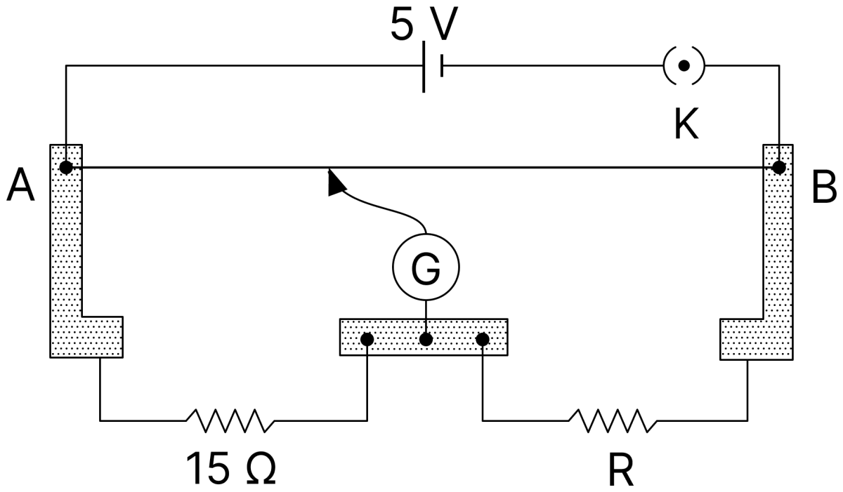
A meter bridge setup is shown in the figure. It is used to determine an unknown resistance R using a given resistor of 15 &Omega;. The galvanometer (G) shows null deflection when tapping key is at 43 cm mark from end A. If the end correction for end A is 2 cm, then the determined value of R will be............... &Omega;. DC Circuits and Measurements, Nootan Physics Solutions ICS Class 12

Answer

Given,

  • Known resistance = 15 Ω in the left gap
  • Balancing length from A = 43 cm
  • End correction for the end A = 2 cm

The corrected balancing length from A is

l=43+2l=45 cm\text l = 43 + 2 \\[1em] \text l = 45\ \text{cm}

and the length of the other portion is 100 − 43 = 57 cm.

Applying the balance condition,

15R=4557R=15×5745R=19 Ω\dfrac{15}{\text R} = \dfrac{45}{57} \\[1em] \text R = 15 \times \dfrac{57}{45} \\[1em] \text R = 19\ \Omega

Hence, the determined value of R is 19 Ω.

Question 17

In order to measure the internal resistance r1 of a cell of emf E, a meter bridge of wire resistance R0 = 50 Ω, a resistance R0/2, another cell of emf E/2 (internal resistance r) and a galvanometer G are used in a circuit, as shown in the figure. If the null point is found at I = 72 cm, then the value of r1 = ............... Ω.
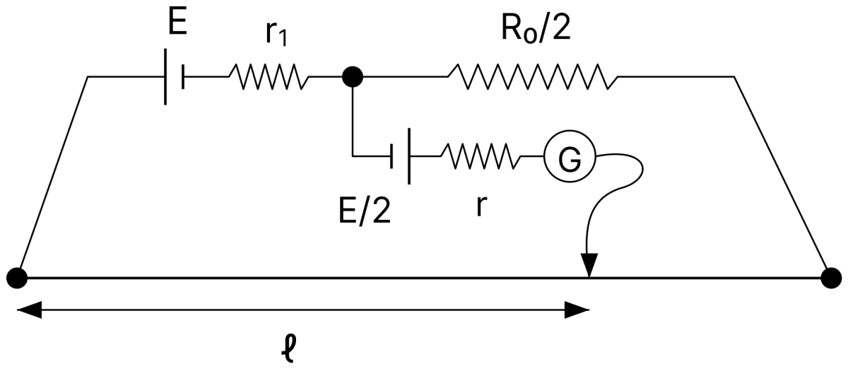
In order to measure the internal resistance r 1 of a cell of emf E, a meter bridge of wire resistance R 0 = 50 &Omega;, a resistance R 0 /2, another cell of emf E/2 (internal resistance r) and a galvanometer G are used in a circuit, as shown in the figure. If the null point is found at I = 72 cm, then the value of r 1 =............... &Omega;. DC Circuits and Measurements, Nootan Physics Solutions ICS Class 12

Answer

Given,

  • Resistance of the bridge wire, R0 = 50 Ω
  • Series resistance = R0/2
  • Emf of the driving cell = E with internal resistance r1
  • Emf of the cell in the secondary circuit = E/2
  • Balancing length, l = 72 cm

The current in the main circuit is

I=Er1+R02+R0I=Er1+3R02\text I = \dfrac{\text E}{\text r_1 + \dfrac{\text R_0}{2} + \text R_0} \\[1em] \text I = \dfrac{\text E}{\text r_1 + \dfrac{3\text R_0}{2}}

Let A and B be the left and right ends of the bridge wire, C the null point on it (AC = 72 cm, so the resistance of AC is 0.72 R0) and M the junction of r1 and R0/2, to which the cell E/2 is connected. At the null point no current flows through the galvanometer, so the current I flows through the whole wire from A to B.

Applying Kirchhoff's second law (∑IR=∑E\sum \text{IR} = \sum \text E) to the mesh ACMA, the cell E is crossed from its negative to its positive electrode and the cell E/2 from its positive to its negative electrode,

0.72 IR0+Ir1=E−E2E2=I (0.72 R0+r1)0.72\ \text{IR}_0 + \text{Ir}_1 = \text E - \dfrac{\text E}{2} \\[1em] \dfrac{\text E}{2} = \text I\ (0.72\ \text R_0 + \text r_1)

Substituting for I,

E2=E (0.72 R0+r1)r1+1.5 R0r1+1.5 R0=2 r1+1.44 R0r1=0.06 R0r1=0.06×50r1=3 Ω\dfrac{\text E}{2} = \dfrac{\text E\ (0.72\ \text R_0 + \text r_1)}{\text r_1 + 1.5\ \text R_0} \\[1em] \text r_1 + 1.5\ \text R_0 = 2\ \text r_1 + 1.44\ \text R_0 \\[1em] \text r_1 = 0.06\ \text R_0 \\[1em] \text r_1 = 0.06 \times 50 \\[1em] \text r_1 = 3\ \Omega

Hence, the value of r1 is 3 Ω.

Question 18

Twelve wires each having resistance 2Ω are joined to form a cube. A battery of 6 V emf is joined across points a and c. The voltage difference between e and f is ............... V.
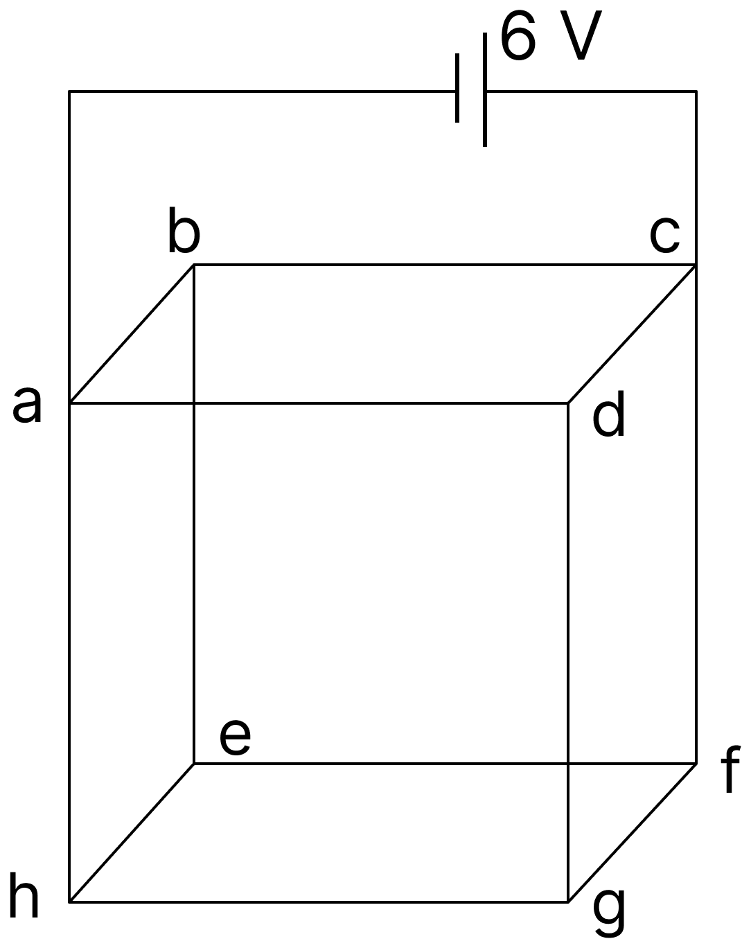
Twelve wires each having resistance 2&Omega; are joined to form a cube. A battery of 6 V emf is joined across points a and c. The voltage difference between e and f is............... V. DC Circuits and Measurements, Nootan Physics Solutions ICS Class 12

Answer

Given,

  • Resistance of each wire = 2 Ω
  • Emf of the battery = 6 V, connected across the face diagonal ac

For a cube of twelve equal resistances, the equivalent resistance across a face diagonal is

Req=34 RReq=34×2Req=32 Ω\text R_\text{eq} = \dfrac{3}{4}\ \text R \\[1em] \text R_\text{eq} = \dfrac{3}{4} \times 2 \\[1em] \text R_\text{eq} = \dfrac{3}{2}\ \Omega

The current drawn from the battery is

I=632I=4 A\text I = \dfrac{6}{\dfrac{3}{2}} \\[1em] \text I = 4\ \text A

By the symmetry of the cube about the diagonal ac, the current entering at a divides so that a current I2 = 1 A flows along the branch ae, and this current divides equally at e.

Hence the current in the wire ef is

I22=0.5 A\dfrac{\text I_2}{2} = 0.5\ \text A

The potential difference between e and f is

ΔV=0.5×2ΔV=1 V\Delta \text V = 0.5 \times 2 \\[1em] \Delta \text V = 1\ \text V

Hence, the voltage difference between e and f is 1 V.

PrevNext