KnowledgeBoat Logo
|
OPEN IN APP

Chapter 4

Capacitors and Dielectrics — Numericals

Class 12 - Nootan Physics


Numericals

Question 1

A conductor when charged to 1000 V , takes 2 µC of charge. Find the capacity of the conductor.

Answer

Given,

  • Potential of the conductor, V = 1000 V
  • Charge taken, Q = 2 µC = 2 × 10⁻⁶ C

The capacitance of a conductor is defined as

C=QV\text C = \dfrac{\text Q}{\text V}

Substituting the values,

C=2×10−61000C=2×10⁻⁹ FC=2×10⁻³ μF\text C = \dfrac{2 \times 10^{-6}}{1000} \\[1em] \text C = 2 \times 10^{-9}\ \text F \\[1em] \text C = 2 \times 10^{-3}\ \mu\text F

Hence, the capacity of the conductor is 2 × 10⁻³ µF.

Question 2

The capacitance of a spherical conductor is 1 µF. What is its diameter?

Answer

Given,

  • Capacitance of the spherical conductor, C = 1 µF = 1 × 10⁻⁶ F

For an isolated spherical conductor of radius a,

C=4πϵ0aa=C4πϵ0a=C×9.0×10⁹\text C = 4\pi\epsilon_0 \text a \\[1em] \text a = \dfrac{\text C}{4\pi\epsilon_0} \\[1em] \text a = \text C \times 9.0 \times 10^9

Substituting the value of C,

a=(1×10⁻⁶)(9.0×10⁹)a=9×10³ m\text a = (1 \times 10^{-6})(9.0 \times 10^9) \\[1em] \text a = 9 \times 10^3\ \text m

The diameter is twice the radius,

D=2aD=2×9×103D=1.8×10⁴ m\text D = 2\text a \\[1em] \text D = 2 \times 9 \times 10^3 \\[1em] \text D = 1.8 \times 10^4\ \text m

Hence, the diameter of the spherical conductor is 1.8 × 10⁴ m.

Question 3

A PD of 250 V exists across the plates of a 25 µF capacitor. Find the charge on each plate.

Answer

Given,

  • Capacitance, C = 25 µF = 25 × 10-6 F
  • Potential difference, V = 250 V

The charge on the plates of a capacitor is

Q=CV\text Q = \text{CV}

Substituting the values,

Q=(25×10−6)(250)Q=6.25×10⁻³ C\text Q = (25 \times 10^{-6})(250) \\[1em] \text Q = 6.25 \times 10^{-3}\ \text C

The two plates carry equal and opposite charges.

Hence, the charges on the plates are + 6.25 × 10⁻³ C and − 6.25 × 10⁻³ C.

Question 4

What distance d between the two parallel plates, each of area A = 0.0314 m2, of an air capacitor be kept so that its capacitance is same as of a conducting sphere of radius a = 0.5 m?

Answer

Given,

  • Area of each plate, A = 0.0314 m2
  • Radius of the conducting sphere, a = 0.5 m

The capacitance of the parallel-plate air capacitor is ε0A/d and that of the conducting sphere is 4πε0a. Equating the two,

ϵ0Ad=4πϵ0ad=A4πa\dfrac{\epsilon_0 \text A}{\text d} = 4\pi\epsilon_0 \text a \\[1em] \text d = \dfrac{\text A}{4\pi \text a}

Substituting the values,

d=0.03144×3.14×0.5d=0.03146.28d=5.0×10⁻³ m\text d = \dfrac{0.0314}{4 \times 3.14 \times 0.5} \\[1em] \text d = \dfrac{0.0314}{6.28} \\[1em] \text d = 5.0 \times 10^{-3}\ \text m

Hence, the plates must be kept 5.0 mm apart.

Question 5

An air parallel-plate capacitor has a plate area of 6 × 10⁻³ m2 and a plate separation of 3 mm. Calculate its capacitance. If this capacitor is connected to a 100 V supply. What is the charge on each plate of the capacitor?

Answer

Given,

  • Area of each plate, A = 6 × 10⁻³ m2
  • Separation between the plates, d = 3 mm = 3 × 10⁻³ m
  • Supply voltage, V = 100 V
  • ε0 = 8.85 × 10⁻¹² C2 N-1 m-2

The capacitance of a parallel-plate air capacitor is

C=ϵ0Ad\text C = \dfrac{\epsilon_0 \text A}{\text d}

Substituting the values,

C=(8.85×10⁻¹²)(6×10⁻³)3×10⁻³C=1.77×10⁻¹¹ F≈18 pF\text C = \dfrac{(8.85 \times 10^{-12})(6 \times 10^{-3})}{3 \times 10^{-3}} \\[1em] \text C = 1.77 \times 10^{-11}\ \text F \approx 18\ \text{pF}

The charge on each plate is

Q=CVQ=(1.8×10⁻¹¹)(100)Q=1.8×10⁻⁹ C\text Q = \text{CV} \\[1em] \text Q = (1.8 \times 10^{-11})(100) \\[1em] \text Q = 1.8 \times 10^{-9}\ \text C

Hence, the capacitance is about 18 pF and the charge on each plate is 1.8 × 10⁻⁹ C.

Question 6

The area of each plate of a parallel-plate capacitor is 100 cm2 and the distance between them is 0.05 cm. When it is filled with a dielectric, its capacitance becomes 3.54 × 10⁻¹⁰ F. Find the dielectric constant.

Answer

Given,

  • Area of each plate, A = 100 cm2 = 1 × 10⁻² m2
  • Distance between the plates, d = 0.05 cm = 5 × 10⁻⁴ m
  • Capacitance with the dielectric, C = 3.54 × 10⁻¹⁰ F
  • ε0 = 8.85 × 10⁻¹² C2 N-1 m-2

The capacitance with air between the plates is

C0=ϵ0Ad\text C_0 = \dfrac{\epsilon_0 \text A}{\text d}

Substituting the values,

C0=(8.85×10⁻¹²)(1×10⁻²)5×10⁻⁴C0=1.77×10⁻¹⁰ F\text C_0 = \dfrac{(8.85 \times 10^{-12})(1 \times 10^{-2})}{5 \times 10^{-4}} \\[1em] \text C_0 = 1.77 \times 10^{-10}\ \text F

The dielectric constant is the ratio of the two capacitances,

K=CC0K=3.54×10−101.77×10⁻¹⁰K=2.0\text K = \dfrac{\text C}{\text C_0} \\[1em] \text K = \dfrac{3.54 \times 10^{-10}}{1.77 \times 10^{-10}} \\[1em] \text K = 2.0

Hence, the dielectric constant of the medium is 2.0.

Question 7

How much area of paper will be required to construct a parallel-plate capacitor of 0.004 µF, if the dielectric constant of the paper be 2.5 and its thickness be 0.025 mm?

Answer

Given,

  • Capacitance required, C = 0.004 µF = 4 × 10⁻⁹ F
  • Dielectric constant of the paper, K = 2.5
  • Thickness of the paper, d = 0.025 mm = 2.5 × 10⁻⁵ m

For a capacitor filled with a dielectric,

C=Kϵ0AdA=CdKϵ0\text C = \dfrac{\text K \epsilon_0 \text A}{\text d} \\[1em] \text A = \dfrac{\text{Cd}}{\text K \epsilon_0}

Substituting the values,

A=(4×10⁻⁹)(2.5×10⁻⁵)(2.5)(8.85×10⁻¹²)A=1×10−132.2125×10⁻¹¹A=4.52×10⁻³ m2\text A = \dfrac{(4 \times 10^{-9})(2.5 \times 10^{-5})}{(2.5)(8.85 \times 10^{-12})} \\[1em] \text A = \dfrac{1 \times 10^{-13}}{2.2125 \times 10^{-11}} \\[1em] \text A = 4.52 \times 10^{-3}\ \text m^2

Hence, an area of 4.52 × 10⁻³ m2 of paper will be required.

Question 8

We have a glass slab (K = 7) 4.0 mm thick, a mica foil (K = 6) 0.20 mm thick and an amber plate (K = 2) 2.0 cm thick. Which one be placed between the plates of a parallel-plate capacitor to obtain maximum capacitance?

Answer

Given,

  • Glass slab : K = 7, d = 4.0 mm
  • Mica foil : K = 6, d = 0.20 mm
  • Amber plate : K = 2, d = 2.0 cm = 20 mm

When a slab completely fills the space between the plates, the separation of the plates is equal to the thickness of the slab, so

C=Kϵ0Ad\text C = \dfrac{\text K \epsilon_0 \text A}{\text d}

For a given plate area A, the capacitance is greatest for the material having the largest value of K/d.

Glass:74.0=1.75 mm−1Mica:60.20=30 mm−1Amber:220=0.1 mm−1\text{Glass} : \dfrac{7}{4.0} = 1.75\ \text{mm}^{-1} \\[1em] \text{Mica} : \dfrac{6}{0.20} = 30\ \text{mm}^{-1} \\[1em] \text{Amber} : \dfrac{2}{20} = 0.1\ \text{mm}^{-1}

Hence, the mica foil should be placed between the plates, since K/d is maximum for it.

Question 9

The potential difference between the plates of a parallel-plate capacitor is 200 V. The area of each plate is 100 cm2 and the distance between them is 1 mm. If the medium between them is air, then calculate the charge taken by the capacitor. If there is a medium of dielectric constant 2.5 between the plates, then what will be the potential difference for the same charge?

Answer

Given,

  • Potential difference, V = 200 V
  • Area of each plate, A = 100 cm2 = 1 × 10⁻² m2
  • Distance between the plates, d = 1 mm = 1 × 10⁻³ m
  • Dielectric constant of the medium, K = 2.5

The capacitance with air between the plates is

C0=ϵ0AdC0=(8.85×10⁻¹²)(1×10⁻²)1×10⁻³C0=8.85×10⁻¹¹ F\text C_0 = \dfrac{\epsilon_0 \text A}{\text d} \\[1em] \text C_0 = \dfrac{(8.85 \times 10^{-12})(1 \times 10^{-2})}{1 \times 10^{-3}} \\[1em] \text C_0 = 8.85 \times 10^{-11}\ \text F

Hence the charge taken by the capacitor is

Q=C0VQ=(8.85×10⁻¹¹)(200)Q=1.76×10⁻⁸ C\text Q = \text C_0 \text V \\[1em] \text Q = (8.85 \times 10^{-11})(200) \\[1em] \text Q = 1.76 \times 10^{-8}\ \text C

On introducing the medium the capacitance becomes KC0, while the charge is the same. Therefore

V′=QKC0V′=VKV′=2002.5V′=80 V\text V' = \dfrac{\text Q}{\text K \text C_0} \\[1em] \text V' = \dfrac{\text V}{\text K} \\[1em] \text V' = \dfrac{200}{2.5} \\[1em] \text V' = 80\ \text V

Hence, the charge taken is 1.76 × 10⁻⁸ C and the new potential difference is 80 V.

Question 10

A paper is placed between two plates of copper, area of each 100 cm2. The thickness of the paper is 0.005 cm and its dielectric constant is 2.5. If the paper can bear an electric field of 5 × 10⁵ V/cm, then calculate the maximum voltage up to which the capacitor can be charged. How much charge will be stored on the capacitor?

Answer

Given,

  • Area of each plate, A = 100 cm2 = 1 × 10⁻² m2
  • Thickness of the paper, d = 0.005 cm = 5 × 10⁻⁵ m
  • Dielectric constant, K = 2.5
  • Maximum field the paper can bear, Emax = 5 × 10⁵ V cm-1 = 5 × 10⁷ V m-1

The maximum voltage is

Vmax=Emax dVmax=(5×10⁷)(5×10⁻⁵)Vmax=2500 V\text V_\text{max} = \text E_\text{max}\thinspace\text d \\[1em] \text V_\text{max} = (5 \times 10^7)(5 \times 10^{-5}) \\[1em] \text V_\text{max} = 2500\ \text V

The capacitance of the arrangement is

C=Kϵ0AdC=(2.5)(8.85×10⁻¹²)(1×10⁻²)5×10⁻⁵C=4.425×10⁻⁹ F\text C = \dfrac{\text K \epsilon_0 \text A}{\text d} \\[1em] \text C = \dfrac{(2.5)(8.85 \times 10^{-12})(1 \times 10^{-2})}{5 \times 10^{-5}} \\[1em] \text C = 4.425 \times 10^{-9}\ \text F

Hence the charge stored at this voltage is

Q=C VmaxQ=(4.425×10⁻⁹)(2500)Q=1.1×10⁻⁵ C\text Q = \text C\thinspace\text V_\text{max} \\[1em] \text Q = (4.425 \times 10^{-9})(2500) \\[1em] \text Q = 1.1 \times 10^{-5}\ \text C

Hence, the capacitor can be charged up to 2500 V and the charge stored is 1.1 × 10⁻⁵ C.

Question 11

When a 20 V battery is connected to an air-capacitor, a charge of 30 µC is obtained on the capacitor. When oil is filled between the plates of the capacitor, then a charge of 75 µC is obtained. Calculate (i) the dielectric constant of the oil, (ii) the energy contained in the oil-capacitor.

Answer

Given,

  • EMF of the battery, V = 20 V
  • Charge with air, Q0 = 30 µC
  • Charge with oil, Q = 75 µC

(i) The capacitances in the two cases are

C0=Q0VC0=3020C0=1.5 μFC=QVC=7520C=3.75 μF\text C_0 = \dfrac{\text Q_0}{\text V} \\[1em] \text C_0 = \dfrac{30}{20} \\[1em] \text C_0 = 1.5\ \mu\text F \\[1em] \text C = \dfrac{\text Q}{\text V} \\[1em] \text C = \dfrac{75}{20} \\[1em] \text C = 3.75\ \mu\text F

Hence the dielectric constant of the oil is

K=CC0K=3.751.5K=2.5\text K = \dfrac{\text C}{\text C_0} \\[1em] \text K = \dfrac{3.75}{1.5} \\[1em] \text K = 2.5

(ii) The energy contained in the oil-capacitor is

U=12CV2U=12(3.75×10⁻⁶)(20)2U=12(3.75×10⁻⁶)(400)U=7.5×10⁻⁴ J\text U = \dfrac{1}{2}\text{CV}^2 \\[1em] \text U = \dfrac{1}{2}(3.75 \times 10^{-6})(20)^2 \\[1em] \text U = \dfrac{1}{2}(3.75 \times 10^{-6})(400) \\[1em] \text U = 7.5 \times 10^{-4}\ \text J

Hence, the dielectric constant of the oil is 2.5 and the energy contained is 7.5 × 10⁻⁴ J.

Question 12

(a) A parallel-plate air capacitor has a plate area of 6 × 10⁻³ m2 and a plate separation of 3 mm. A PD of 100 V is established between its plates by a battery. After disconnecting the battery, the space between the plates is filled by a 3 mm thick mica sheet of dielectric constant K = 6. Find (i) the new PD between the plates, (ii) the final capacitance and (iii) the final charge on the capacitor.

(b) If the battery remains connected to the capacitor, then what will be the answers of the above parts.

Answer

Given,

  • Plate area, A = 6 × 10⁻³ m2
  • Plate separation, d = 3 mm = 3 × 10⁻³ m
  • Potential difference, V = 100 V
  • Dielectric constant of mica, K = 6

The capacitance with air is

C0=ϵ0AdC0=(8.85×10⁻¹²)(6×10⁻³)3×10⁻³C0=1.77×10⁻¹¹ F≈18 pF\text C_0 = \dfrac{\epsilon_0 \text A}{\text d} \\[1em] \text C_0 = \dfrac{(8.85 \times 10^{-12})(6 \times 10^{-3})}{3 \times 10^{-3}} \\[1em] \text C_0 = 1.77 \times 10^{-11}\ \text F \approx 18\ \text{pF}

and the initial charge is

Q0=C0VQ0=(18×10−12)(100)Q0=1.8×10⁻⁹ C\text Q_0 = \text C_0 \text V \\[1em] \text Q_0 = (18 \times 10^{-12})(100) \\[1em] \text Q_0 = 1.8 \times 10^{-9}\ \text C

Since the mica sheet is 3 mm thick, it completely fills the space between the plates, so the final capacitance in both the cases is

C=KC0C=6×18C=108 pF\text C = \text{KC}_0 \\[1em] \text C = 6 \times 18 \\[1em] \text C = 108\ \text{pF}

(a) Battery disconnected : the charge on the plates cannot change.

(i) The new potential difference is

V′=VKV′=1006 V\text V' = \dfrac{\text V}{\text K} \\[1em] \text V' = \dfrac{100}{6}\ \text V

(ii) The final capacitance is 108 pF.

(iii) The final charge is the same as before, that is, 1.8 × 10⁻⁹ C.

(b) Battery remaining connected : the potential difference is fixed by the battery.

(i) The potential difference remains 100 V.

(ii) The final capacitance is again 108 pF.

(iii) The final charge is

Q=CVQ=(108×10−12)(100)Q=1.08×10⁻⁸ C\text Q = \text{CV} \\[1em] \text Q = (108 \times 10^{-12})(100) \\[1em] \text Q = 1.08 \times 10^{-8}\ \text C

Question 13

(a) A parallel-plate capacitor has a plate-area of 90 cm2 and separation 2.5 mm. Find the stored electrostatic energy when it is charged to 400 V.

(b) The energy is stored in the electrostatic field between the capacitor plates. Obtain energy density (energy per unit volume).

Answer

Given,

  • Plate area, A = 90 cm2 = 9 × 10⁻³ m2
  • Separation, d = 2.5 mm = 2.5 × 10⁻³ m
  • Potential difference, V = 400 V

(a) The capacitance is

C=ϵ0AdC=(8.85×10⁻¹²)(9×10⁻³)2.5×10⁻³C=3.186×10⁻¹¹ F\text C = \dfrac{\epsilon_0 \text A}{\text d} \\[1em] \text C = \dfrac{(8.85 \times 10^{-12})(9 \times 10^{-3})}{2.5 \times 10^{-3}} \\[1em] \text C = 3.186 \times 10^{-11}\ \text F

Hence the stored electrostatic energy is

U=12CV2U=12(3.186×10⁻¹¹)(400)2U=12(3.186×10⁻¹¹)(1.6×10⁵)U=2.55×10⁻⁶ J\text U = \dfrac{1}{2}\text{CV}^2 \\[1em] \text U = \dfrac{1}{2}(3.186 \times 10^{-11})(400)^2 \\[1em] \text U = \dfrac{1}{2}(3.186 \times 10^{-11})(1.6 \times 10^5) \\[1em] \text U = 2.55 \times 10^{-6}\ \text J

(b) The field exists only in the space between the plates, whose volume is

Ad=(9×10⁻³)(2.5×10⁻³)Ad=2.25×10⁻⁵ m3\text{Ad} = (9 \times 10^{-3})(2.5 \times 10^{-3}) \\[1em] \text{Ad} = 2.25 \times 10^{-5}\ \text m^3

Hence the energy density is

u=UAdu=2.55×10−62.25×10−5u=0.113 J m−3\text u = \dfrac{\text U}{\text{Ad}} \\[1em] \text u = \dfrac{2.55 \times 10^{-6}}{2.25 \times 10^{-5}} \\[1em] \text u = 0.113\ \text J\ \text m^{-3}

Hence, the stored energy is 2.55 × 10⁻⁶ J and the energy density is 0.113 J m-3.

Question 14

A parallel-plate 100 µF capacitor is charged to 500 V and the charging battery is removed. If the distance between its plates is halved, then what will be the new potential difference between the plates and what will be the change in the stored energy?

Answer

Given,

  • Capacitance, C = 100 µF
  • Potential difference, V = 500 V
  • The charging battery is removed, so the charge Q remains constant

Since C = ε0A/d, on halving the separation the capacitance becomes

C′=2C\text C' = 2\text C

The new potential difference is

V′=QC′V′=CV2CV′=V2V′=5002V′=250 V\text V' = \dfrac{\text Q}{\text C'} \\[1em] \text V' = \dfrac{\text{CV}}{2\text C} \\[1em] \text V' = \dfrac{\text V}{2} \\[1em] \text V' = \dfrac{500}{2} \\[1em] \text V' = 250\ \text V

The stored energy in terms of the constant charge is U = Q2/2C, so

U′U=CC′U′U=12\dfrac{\text U'}{\text U} = \dfrac{\text C}{\text C'} \\[1em] \dfrac{\text U'}{\text U} = \dfrac{1}{2}

Hence, the new potential difference is 250 V and the stored energy is halved.

Question 15

A 16 µF capacitor is charged to 3.2 × 10⁻⁴ C and the charging battery is disconnected. What will be the work required in doubling the distance between the plates?

Answer

Given,

  • Capacitance, C = 16 µF = 16 × 10-6 F
  • Charge, Q = 3.2 × 10⁻⁴ C
  • The battery is disconnected, so Q remains constant

On doubling the separation the capacitance is halved,

C′=C2C′=8×10⁻⁶ F\text C' = \dfrac{\text C}{2} \\[1em] \text C' = 8 \times 10^{-6}\ \text F

The work required is equal to the increase in the stored energy,

W=Q22C′−Q22CW=Q22(1C′−1C)\text W = \dfrac{\text Q^2}{2\text C'} - \dfrac{\text Q^2}{2\text C} \\[1em] \text W = \dfrac{\text Q^2}{2}\left(\dfrac{1}{\text C'} - \dfrac{1}{\text C}\right)

Substituting the values,

W=(3.2×10⁻⁴)22(18×10−6−116×10−6)=1.024×10−72(1.25×10⁵−0.625×10⁵)=(5.12×10⁻⁸)(6.25×10⁴)W=3.2×10⁻³ J\text W = \dfrac{(3.2 \times 10^{-4})^2}{2}\left(\dfrac{1}{8 \times 10^{-6}} - \dfrac{1}{16 \times 10^{-6}}\right) \\[1em] = \dfrac{1.024 \times 10^{-7}}{2}\left(1.25 \times 10^5 - 0.625 \times 10^5\right) \\[1em] = (5.12 \times 10^{-8})(6.25 \times 10^4) \\[1em] \text W = 3.2 \times 10^{-3}\ \text J

Hence, the work required is 3.2 × 10⁻³ J.

Question 16

A 6 µF capacitor is raised in PD from 10 to 20 V. Compute increase in electric potential energy.

Answer

Given,

  • Capacitance, C = 6 µF = 6 × 10⁻⁶ F
  • Initial potential difference, V1 = 10 V
  • Final potential difference, V2 = 20 V

The energy stored is U = ½CV2, so the increase in the potential energy is

ΔU=12C(V22−V12)\Delta \text U = \dfrac{1}{2}\text C\left(\text V_2^2 - \text V_1^2\right)

Substituting the values,

ΔU=12(6×10⁻⁶)[(20)2−(10)2]ΔU=12(6×10⁻⁶)(400−100)ΔU=12(6×10⁻⁶)(300)ΔU=9×10⁻⁴ J\Delta \text U = \dfrac{1}{2}(6 \times 10^{-6})\left[(20)^2 - (10)^2\right] \\[1em] \Delta \text U = \dfrac{1}{2}(6 \times 10^{-6})(400 - 100) \\[1em] \Delta \text U = \dfrac{1}{2}(6 \times 10^{-6})(300) \\[1em] \Delta \text U = 9 \times 10^{-4}\ \text J

Hence, the increase in electric potential energy is 9 × 10⁻⁴ J.

Question 17

The capacitance of a variable capacitor connected to a 10 V battery is changed from 7 to 3 µF. Compute energy-change.

Answer

Given,

  • Initial capacitance, C1 = 7 µF = 7 × 10⁻⁶ F
  • Final capacitance, C2 = 3 µF = 3 × 10⁻⁶ F
  • Potential difference, V = 10 V

The battery remains connected, so V is constant and U = ½CV2. The change in energy is

ΔU=12(C2−C1)V2\Delta \text U = \dfrac{1}{2}\left(\text C_2 - \text C_1\right)\text V^2

Substituting the values,

ΔU=12(3×10⁻⁶−7×10⁻⁶)(10)2ΔU=12(−4×10⁻⁶)(100)ΔU=−2×10⁻⁴ J\Delta \text U = \dfrac{1}{2}(3 \times 10^{-6} - 7 \times 10^{-6})(10)^2 \\[1em] \Delta \text U = \dfrac{1}{2}(-4 \times 10^{-6})(100) \\[1em] \Delta \text U = -2 \times 10^{-4}\ \text J

The negative sign shows that the energy of the capacitor decreases.

Hence, 2 × 10⁻⁴ J of energy will be transferred to the battery.

Question 18

The capacitance of a variable radio capacitor can be changed from 50 pF to 950 pF by tuning the dial from 0 to 180°. With the dial set at 180°, the capacitor is connected to a 400 V battery. After charging, the capacitor is disconnected from the battery and the dial is turned to 0. (a) What is the potential difference across the capacitor when the dial reads 0? (b) How much work is required to turn the dial, if friction is neglected?

Answer

Given,

  • Capacitance at 180°, C1 = 950 pF = 9.5 × 10⁻¹⁰ F
  • Capacitance at 0, C2 = 50 pF = 5 × 10-11 F
  • Charging voltage, V1 = 400 V

The charge given to the capacitor is

Q=C1V1Q=(9.5×10⁻¹⁰)(400)Q=3.8×10⁻⁷ C\text Q = \text C_1 \text V_1 \\[1em] \text Q = (9.5 \times 10^{-10})(400) \\[1em] \text Q = 3.8 \times 10^{-7}\ \text C

(a) The capacitor is disconnected from the battery, so this charge remains constant. When the dial reads 0,

V2=QC2V2=3.8×10−75×10−11V2=7600 V\text V_2 = \dfrac{\text Q}{\text C_2} \\[1em] \text V_2 = \dfrac{3.8 \times 10^{-7}}{5 \times 10^{-11}} \\[1em] \text V_2 = 7600\ \text V

(b) The work required is equal to the increase in the stored energy,

W=Q22C2−Q22C1W=12Q(V2−V1)\text W = \dfrac{\text Q^2}{2\text C_2} - \dfrac{\text Q^2}{2\text C_1} \\[1em] \text W = \dfrac{1}{2}\text Q\left(\text V_2 - \text V_1\right)

Substituting the values,

W=12(3.8×10⁻⁷)(7600−400)W=12(3.8×10⁻⁷)(7200)W=1.368×10⁻³ J\text W = \dfrac{1}{2}(3.8 \times 10^{-7})(7600 - 400) \\[1em] \text W = \dfrac{1}{2}(3.8 \times 10^{-7})(7200) \\[1em] \text W = 1.368 \times 10^{-3}\ \text J

Hence, the potential difference is 7600 V and the work required is 1.368 × 10⁻³ J.

Question 19

In a camera-flash circuit, a 2000 µF capacitor is charged by a 1.5 V cell. When a flash is required, the energy stored in the capacitor is discharged by means of a trigger T through a discharge tube D in 0.1 millisecond. Find the energy stored in the capacitor and the power of the flash.
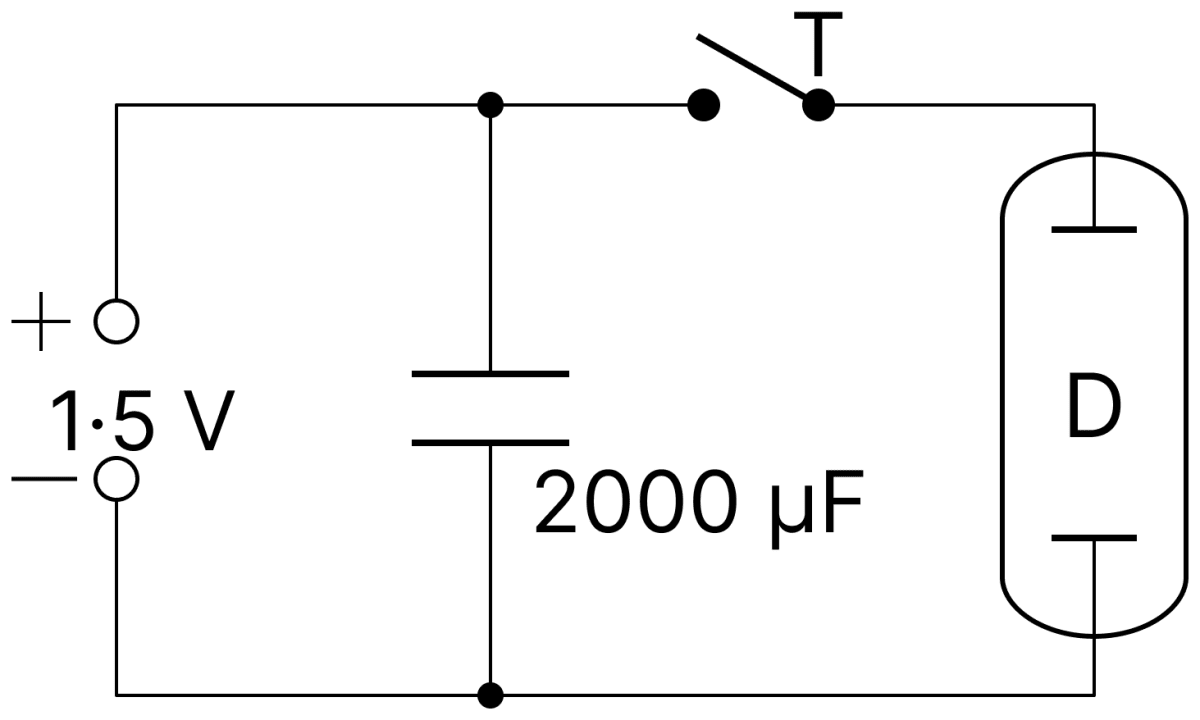
In a camera-flash circuit, a 2000 µF capacitor is charged by a 1.5 V cell. When a flash is required, the energy stored in the capacitor is discharged by means of a trigger T through a discharge tube D in 0.1 millisecond. Find the energy stored in the capacitor and the power of the flash. Capacitors Dielectrics, Nootan Physics Solutions ICS Class 12

Answer

Given,

  • Capacitance, C = 2000 µF = 2 × 10⁻³ F
  • EMF of the cell, V = 1.5 V
  • Time of discharge, t = 0.1 millisecond = 1 × 10⁻⁴ s

The energy stored in the capacitor is

U=12CV2\text U = \dfrac{1}{2}\text{CV}^2

Substituting the values,

U=12(2×10⁻³)(1.5)2U=12(2×10⁻³)(2.25)U=2.25×10⁻³ J\text U = \dfrac{1}{2}(2 \times 10^{-3})(1.5)^2 \\[1em] \text U = \dfrac{1}{2}(2 \times 10^{-3})(2.25) \\[1em] \text U = 2.25 \times 10^{-3}\ \text J

The whole of this energy is released in the time t, so the power of the flash is

P=UtP=2.25×10−31×10−4P=22.5 W\text P = \dfrac{\text U}{\text t} \\[1em] \text P = \dfrac{2.25 \times 10^{-3}}{1 \times 10^{-4}} \\[1em] \text P = 22.5\ \text W

Hence, the energy stored is 2.25 × 10⁻³ J and the power of the flash is 22.5 W.

Question 20

Three equal 9 pF capacitors are connected in series. Find (a) the total capacitance of the combination, (b) PD across each capacitor if the combination is connected to a 120 V supply.

Answer

Given,

  • Three equal capacitors, each of capacitance C = 9 pF
  • Supply voltage, V = 120 V

(a) For three equal capacitors in series,

1Cs=19+19+191Cs=39Cs=3 pF\dfrac{1}{\text C_s} = \dfrac{1}{9} + \dfrac{1}{9} + \dfrac{1}{9} \\[1em] \dfrac{1}{\text C_s} = \dfrac{3}{9} \\[1em] \text C_s = 3\ \text{pF}

(b) The capacitors are identical and carry the same charge, so the applied potential difference divides equally between them,

V1=V2=V3=1203V1=V2=V3=40 V\text V_1 = \text V_2 = \text V_3 = \dfrac{120}{3} \\[1em] \text V_1 = \text V_2 = \text V_3 = 40\ \text V

Hence, the total capacitance is 3 pF and the PD across each capacitor is 40 V.

Question 21

Three capacitors of 2 pF, 3 pF and 4 pF capacitances are connected in parallel. Find (a) the total capacitance of the combination, (b) charge on each capacitor if the combination is connected to a 100 V supply.

Answer

Given,

  • C1 = 2 pF, C2 = 3 pF, C3 = 4 pF, connected in parallel
  • Supply voltage, V = 100 V

(a) For a parallel combination,

Cp=C1+C2+C3Cp=2+3+4Cp=9 pF\text C_p = \text C_1 + \text C_2 + \text C_3 \\[1em] \text C_p = 2 + 3 + 4 \\[1em] \text C_p = 9\ \text{pF}

(b) In parallel each capacitor has the full supply voltage across it, so

Q1=C1VQ1=(2×10⁻¹²)(100)Q1=2×10⁻¹⁰ CQ2=C2VQ2=(3×10⁻¹²)(100)Q2=3×10⁻¹⁰ CQ3=C3VQ3=(4×10⁻¹²)(100)Q3=4×10⁻¹⁰ C\text Q_1 = \text C_1 \text V \\[1em] \text Q_1 = (2 \times 10^{-12})(100) \\[1em] \text Q_1 = 2 \times 10^{-10}\ \text C \\[1em] \text Q_2 = \text C_2 \text V \\[1em] \text Q_2 = (3 \times 10^{-12})(100) \\[1em] \text Q_2 = 3 \times 10^{-10}\ \text C \\[1em] \text Q_3 = \text C_3 \text V \\[1em] \text Q_3 = (4 \times 10^{-12})(100) \\[1em] \text Q_3 = 4 \times 10^{-10}\ \text C

Hence, the total capacitance is 9 pF and the charges are 2 × 10⁻¹⁰ C, 3 × 10⁻¹⁰ C and 4 × 10⁻¹⁰ C respectively.

Question 22

How and how many capacitors each having capacitance of 2.0 µF should be connected so that the total potential difference of the arrangement becomes 300 V, if the arrangement is given a charge of 75 µC.

Answer

Given,

  • Capacitance of each capacitor, C = 2.0 µF
  • Total potential difference, V = 300 V
  • Charge given to the arrangement, Q = 75 µC

The equivalent capacitance of the arrangement must be

Ceq=QVCeq=75300Ceq=0.25 μF\text C_\text{eq} = \dfrac{\text Q}{\text V} \\[1em] \text C_\text{eq} = \dfrac{75}{300} \\[1em] \text C_\text{eq} = 0.25\ \mu\text F

Since the equivalent capacitance is smaller than the capacitance of a single capacitor, the capacitors must be joined in series. For n capacitors each of capacitance C in series,

Ceq=Cn0.25=2.0nn=8\text C_\text{eq} = \dfrac{\text C}{\text n} \\[1em] 0.25 = \dfrac{2.0}{\text n} \\[1em] \text n = 8

Hence, 8 capacitors should be connected in series.

Question 23

We have two variable capacitors; each of them can be varied from 10 pF to 500 pF. What minimum and maximum capacitances can be obtained by combining them?

Answer

Given,

  • Each capacitor can be varied from 10 pF to 500 pF

Minimum capacitance : This is obtained when both are set to their least value and joined in series,

Cmin=C1C2C1+C2Cmin=10×1010+10Cmin=5 pF\text C_\text{min} = \dfrac{\text C_1 \text C_2}{\text C_1 + \text C_2} \\[1em] \text C_\text{min} = \dfrac{10 \times 10}{10 + 10} \\[1em] \text C_\text{min} = 5\ \text{pF}

Maximum capacitance : This is obtained when both are set to their greatest value and joined in parallel,

Cmax=C1+C2Cmax=500+500Cmax=1000 pF\text C_\text{max} = \text C_1 + \text C_2 \\[1em] \text C_\text{max} = 500 + 500 \\[1em] \text C_\text{max} = 1000\ \text{pF}

Hence, the minimum and maximum capacitances obtainable are 5 pF and 1000 pF.

Question 24

Three equal capacitors joined in parallel take a total charge of 1.8 µC from a 2 V cell. How much charge will they take from the same cell, if joined in series?

Answer

Given,

  • Total charge taken in parallel, Qp = 1.8 µC
  • EMF of the cell, V = 2 V
  • Number of equal capacitors = 3

In parallel the equivalent capacitance is 3C, so

Qp=(3C)V1.8=(3C)(2)C=0.3 μF\text Q_p = (3\text C)\text V \\[1em] 1.8 = (3\text C)(2) \\[1em] \text C = 0.3\ \mu\text F

In series the equivalent capacitance is

Cs=C3Cs=0.33Cs=0.1 μF\text C_s = \dfrac{\text C}{3} \\[1em] \text C_s = \dfrac{0.3}{3} \\[1em] \text C_s = 0.1\ \mu\text F

The charge taken from the same cell is

Qs=CsVQs=(0.1)(2)Qs=0.2 μC\text Q_s = \text C_s \text V \\[1em] \text Q_s = (0.1)(2) \\[1em] \text Q_s = 0.2\ \mu\text C

Hence, in series the combination will take a charge of 0.2 µC.

Question 25

Two parallel-plate capacitors, 20 µF and 30 µF are charged to 30 V and 20 V respectively. If their plates with same type of charges are connected together, then find the common PD between the plates of the capacitors.

Answer

Given,

  • C1 = 20 µF charged to V1 = 30 V
  • C2 = 30 µF charged to V2 = 20 V

Since plates carrying the same type of charge are joined together, the two capacitors are connected in parallel and the charges add. By the conservation of charge, the common potential difference is

V=C1V1+C2V2C1+C2\text V = \dfrac{\text C_1 \text V_1 + \text C_2 \text V_2}{\text C_1 + \text C_2}

Substituting the values,

V=(20)(30)+(30)(20)20+30V=600+60050V=120050V=24 V\text V = \dfrac{(20)(30) + (30)(20)}{20 + 30} \\[1em] \text V = \dfrac{600 + 600}{50} \\[1em] \text V = \dfrac{1200}{50} \\[1em] \text V = 24\ \text V

Hence, the common potential difference is 24 V.

Question 26

A 0.2 µF capacitor is charged to a potential of 600 V. After disconnecting the battery, it is connected in parallel to a 1.0 µF capacitor. What will be the new potential?

Answer

Given,

  • C1 = 0.2 µF charged to V1 = 600 V
  • C2 = 1.0 µF, uncharged

The charge on the first capacitor is

Q=C1V1Q=(0.2)(600)Q=120 μC\text Q = \text C_1 \text V_1 \\[1em] \text Q = (0.2)(600) \\[1em] \text Q = 120\ \mu\text C

The battery is disconnected, so this charge is merely shared between the two capacitors joined in parallel. The common potential is

V=QC1+C2V=1200.2+1.0V=1201.2V=100 V\text V = \dfrac{\text Q}{\text C_1 + \text C_2} \\[1em] \text V = \dfrac{120}{0.2 + 1.0} \\[1em] \text V = \dfrac{120}{1.2} \\[1em] \text V = 100\ \text V

Hence, the new potential is 100 V.

Question 27

A 80 µF capacitor is charged by a 50 V battery. The capacitor is disconnected from the battery and then connected across another uncharged 320 µF capacitor. Find the charge on the second capacitor.

Answer

Given,

  • C1 = 80 µF charged to V1 = 50 V
  • C2 = 320 µF, uncharged

The charge on the first capacitor is

Q=C1V1Q=(80)(50)Q=4000 μC\text Q = \text C_1 \text V_1 \\[1em] \text Q = (80)(50) \\[1em] \text Q = 4000\ \mu\text C

On joining the two capacitors in parallel, this charge is shared and the common potential is

V=QC1+C2V=400080+320V=4000400V=10 V\text V = \dfrac{\text Q}{\text C_1 + \text C_2} \\[1em] \text V = \dfrac{4000}{80 + 320} \\[1em] \text V = \dfrac{4000}{400} \\[1em] \text V = 10\ \text V

The charge on the second capacitor is

Q2=C2VQ2=(320)(10)Q2=3200 μC\text Q_2 = \text C_2 \text V \\[1em] \text Q_2 = (320)(10) \\[1em] \text Q_2 = 3200\ \mu\text C

Hence, the charge on the second capacitor is 3200 µC.

Question 28

Two capacitors 4 µF and 2 µF are connected in parallel with a battery of 6 V . Find (i) PD across each capacitor, (ii) charge on each.

Answer

Given,

  • C1 = 4 µF, C2 = 2 µF, connected in parallel
  • EMF of the battery, V = 6 V

(i) In a parallel combination each capacitor has the same potential difference, which equals the emf of the battery.

Hence, the PD across each capacitor is 6 V.

(ii) The charges are

Q1=C1VQ1=(4)(6)Q1=24 μCQ2=C2VQ2=(2)(6)Q2=12 μC\text Q_1 = \text C_1 \text V \\[1em] \text Q_1 = (4)(6) \\[1em] \text Q_1 = 24\ \mu\text C \\[1em] \text Q_2 = \text C_2 \text V \\[1em] \text Q_2 = (2)(6) \\[1em] \text Q_2 = 12\ \mu\text C

Hence, the charges on the 4 µF and 2 µF capacitors are 24 µC and 12 µC respectively.

Question 29

There are three capacitors each of 0.50 µF. Two of these are connected in series and the third is connected in parallel to them. Calculate the capacitance of the combination. If a potential difference of 20 V is applied on the combination, what will be the total charge stored?

Answer

Given,

  • Capacitance of each capacitor, C = 0.50 µF
  • Potential difference applied, V = 20 V

The two capacitors in series give

Cs=C2Cs=0.502Cs=0.25 μF\text C_s = \dfrac{\text C}{2} \\[1em] \text C_s = \dfrac{0.50}{2} \\[1em] \text C_s = 0.25\ \mu\text F

The third capacitor is in parallel with this combination, so

Ceq=Cs+CCeq=0.25+0.50Ceq=0.75 μF\text C_\text{eq} = \text C_s + \text C \\[1em] \text C_\text{eq} = 0.25 + 0.50 \\[1em] \text C_\text{eq} = 0.75\ \mu\text F

The total charge stored is

Q=CeqVQ=(0.75)(20)Q=15 μC\text Q = \text C_\text{eq}\text V \\[1em] \text Q = (0.75)(20) \\[1em] \text Q = 15\ \mu\text C

Hence, the capacitance of the combination is 0.75 µF and the total charge stored is 15 µC.

Question 30

A potential difference of 120 V is applied to combination of two capacitors C1 = 4 µF and C2 = 12 µF connected in series. Calculate (a) the effective capacitance of the combination and (b) the potential difference and charge for each of these two capacitors.

Answer

Given,

  • C1 = 4 µF, C2 = 12 µF, connected in series
  • Applied potential difference, V = 120 V

(a) For a series combination,

Ceq=C1C2C1+C2Ceq=4×124+12Ceq=4816Ceq=3 μF\text C_\text{eq} = \dfrac{\text C_1 \text C_2}{\text C_1 + \text C_2} \\[1em] \text C_\text{eq} = \dfrac{4 \times 12}{4 + 12} \\[1em] \text C_\text{eq} = \dfrac{48}{16} \\[1em] \text C_\text{eq} = 3\ \mu\text F

(b) In series each capacitor carries the same charge,

Q=CeqVQ=(3)(120)Q=360 μC\text Q = \text C_\text{eq}\text V \\[1em] \text Q = (3)(120) \\[1em] \text Q = 360\ \mu\text C

The potential differences are

V1=QC1V1=3604V1=90 VV2=QC2V2=36012V2=30 V\text V_1 = \dfrac{\text Q}{\text C_1} \\[1em] \text V_1 = \dfrac{360}{4} \\[1em] \text V_1 = 90\ \text V \\[1em] \text V_2 = \dfrac{\text Q}{\text C_2} \\[1em] \text V_2 = \dfrac{360}{12} \\[1em] \text V_2 = 30\ \text V

Hence, the effective capacitance is 3 µF; the potential differences are 90 V and 30 V, and the charge on each capacitor is 360 µC.

Question 31

Two capacitors are 2 and 3 µF and are joined in series. The outer plate of the first capacitor is at 1000 V and the outer plate of the second capacitor is earthed. Find out the potential and charge of the inner plate of each capacitor.

Answer

Given,

  • C1 = 2 µF, C2 = 3 µF, joined in series
  • Potential of the outer plate of C1 = 1000 V
  • Outer plate of C2 is earthed, that is, at zero potential

The equivalent capacitance is

Ceq=C1C2C1+C2Ceq=2×32+3Ceq=1.2 μF\text C_\text{eq} = \dfrac{\text C_1 \text C_2}{\text C_1 + \text C_2} \\[1em] \text C_\text{eq} = \dfrac{2 \times 3}{2 + 3} \\[1em] \text C_\text{eq} = 1.2\ \mu\text F

Since the total potential difference across the combination is 1000 V, the charge on each capacitor is

Q=CeqVQ=(1.2×10⁻⁶)(1000)Q=1.2×10⁻³ C\text Q = \text C_\text{eq}\text V \\[1em] \text Q = (1.2 \times 10^{-6})(1000) \\[1em] \text Q = 1.2 \times 10^{-3}\ \text C

The potential difference across C1 is

V1=QC1V1=1.2×10−32×10−6V1=600 V\text V_1 = \dfrac{\text Q}{\text C_1} \\[1em] \text V_1 = \dfrac{1.2 \times 10^{-3}}{2 \times 10^{-6}} \\[1em] \text V_1 = 600\ \text V

Hence the potential of the inner plate of the first capacitor is

1000−600=400 V1000 - 600 = 400\ \text V

The two inner plates are joined together, so the inner plate of the second capacitor is also at 400 V. This is consistent, since the potential difference across C2 is

V2=QC2V2=1.2×10−33×10−6V2=400 V\text V_2 = \dfrac{\text Q}{\text C_2} \\[1em] \text V_2 = \dfrac{1.2 \times 10^{-3}}{3 \times 10^{-6}} \\[1em] \text V_2 = 400\ \text V

Hence, both the inner plates are at 400 V, and each carries a charge of 1.2 × 10⁻³ C.

Question 32

A 100 pF capacitor is charged to a potential difference of 100 V. It is connected in parallel to another capacitor. If the final voltage be 30 V, then what will be the capacitance of the second capacitor? How much energy will be wasted and what will happen to it?

Answer

Given,

  • C1 = 100 pF = 1 × 10⁻¹⁰ F charged to V1 = 100 V
  • Common potential after joining, V = 30 V

The charge on the first capacitor is

Q=C1V1Q=(1×10⁻¹⁰)(100)Q=1×10⁻⁸ C\text Q = \text C_1 \text V_1 \\[1em] \text Q = (1 \times 10^{-10})(100) \\[1em] \text Q = 1 \times 10^{-8}\ \text C

On joining the second capacitor in parallel, this charge is shared, so

C1+C2=QVC1+C2=1×10−830C1+C2=13×10−9 FC2=103×10−10−1×10⁻¹⁰C2=73×10−10 F\text C_1 + \text C_2 = \dfrac{\text Q}{\text V} \\[1em] \text C_1 + \text C_2 = \dfrac{1 \times 10^{-8}}{30} \\[1em] \text C_1 + \text C_2 = \dfrac{1}{3} \times 10^{-9}\ \text F \\[1em] \text C_2 = \dfrac{10}{3} \times 10^{-10} - 1 \times 10^{-10} \\[1em] \text C_2 = \dfrac{7}{3} \times 10^{-10}\ \text F

Energy wasted :

Ui=12C1V12Ui=12(1×10⁻¹⁰)(100)2Ui=5×10⁻⁷ JUf=12(C1+C2)V2Uf=12(13×10−9)(30)2Uf=1.5×10⁻⁷ JΔU=Ui−UfΔU=5×10⁻⁷−1.5×10⁻⁷ΔU=3.5×10⁻⁷ J\text U_i = \dfrac{1}{2}\text C_1 \text V_1^2 \\[1em] \text U_i = \dfrac{1}{2}(1 \times 10^{-10})(100)^2 \\[1em] \text U_i = 5 \times 10^{-7}\ \text J \\[1em] \text U_f = \dfrac{1}{2}(\text C_1 + \text C_2)\text V^2 \\[1em] \text U_f = \dfrac{1}{2}\left(\dfrac{1}{3} \times 10^{-9}\right)(30)^2 \\[1em] \text U_f = 1.5 \times 10^{-7}\ \text J \\[1em] \Delta \text U = \text U_i - \text U_f \\[1em] \Delta \text U = 5 \times 10^{-7} - 1.5 \times 10^{-7} \\[1em] \Delta \text U = 3.5 \times 10^{-7}\ \text J

Hence, the capacitance of the second capacitor is 73×10−10\dfrac{7}{3} \times 10^{-10} F and the energy wasted is 3.5 × 10⁻⁷ J. This energy is dissipated as heat in the connecting wires and as electromagnetic radiation.

Question 33

An electronic flash lamp has 20 capacitors, each of capacitance 5 µF, connected in parallel. The lamp is operated at 100 V. How much energy will be radiated in a flash?

Answer

Given,

  • Number of capacitors, n = 20, each of capacitance C = 5 µF
  • Operating voltage, V = 100 V

For a parallel combination,

Ceq=nCCeq=20×5Ceq=100 μFCeq=100×10−6 F\text C_\text{eq} = \text{nC} \\[1em] \text C_\text{eq} = 20 \times 5 \\[1em] \text C_\text{eq} = 100\ \mu\text F \\[1em] \text C_\text{eq} = 100 \times 10^{-6}\ \text F

The energy stored, which is radiated in one flash, is

U=12CeqV2\text U = \dfrac{1}{2}\text C_\text{eq}\text V^2

Substituting the values,

U=12(100×10−6)(100)2U=12(100×10−6)(104)U=0.5 J\text U = \dfrac{1}{2}(100 \times 10^{-6})(100)^2 \\[1em] \text U = \dfrac{1}{2}(100 \times 10^{-6})(10^4) \\[1em] \text U = 0.5\ \text J

Hence, the energy radiated in a flash is 0.5 J.

Question 34

Three capacitors of capacitance C1 = 3 µF, C2 = 6 µF and C3 = 10 µF, are connected to a 10 V battery as shown in figure.
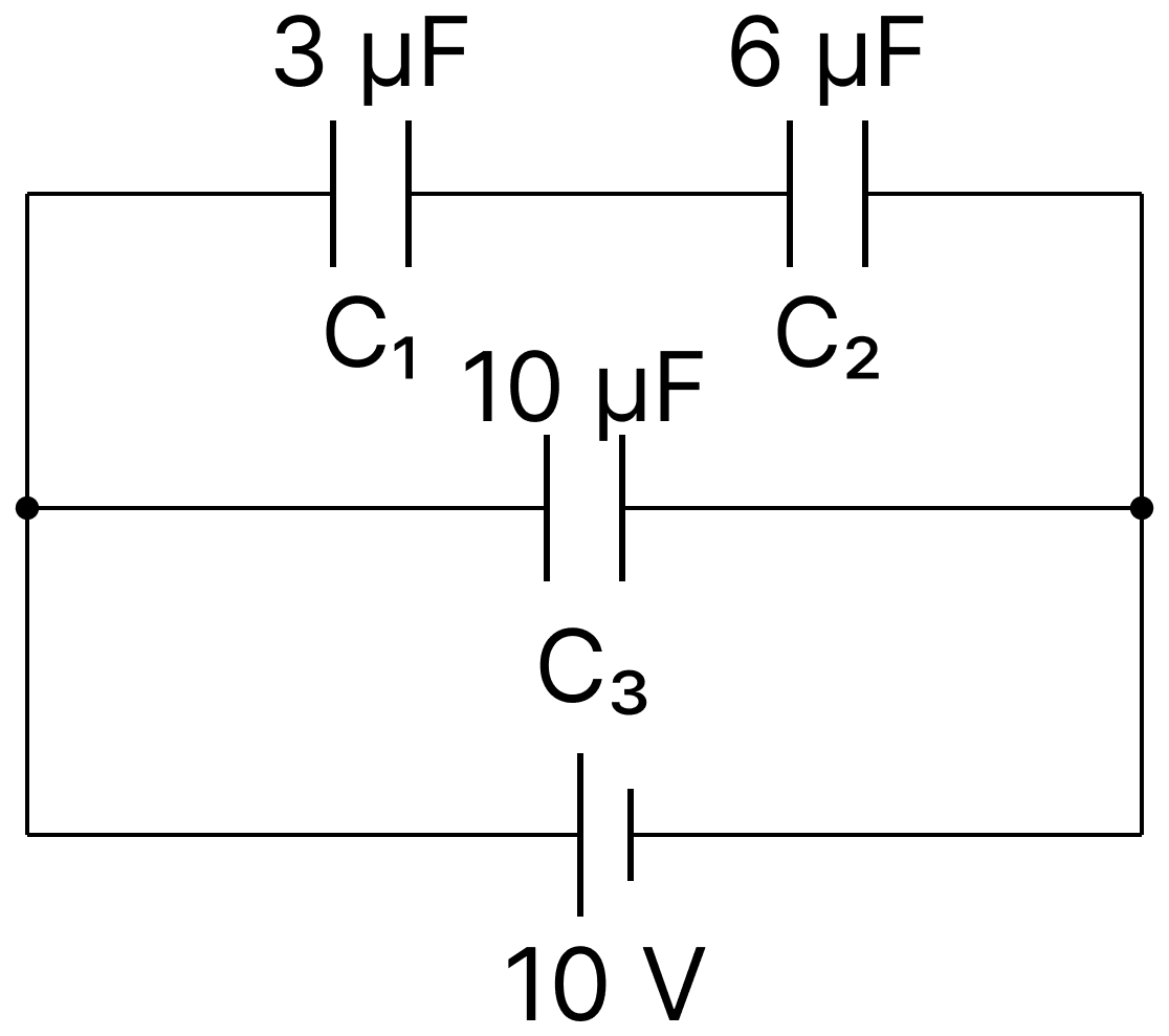
Three capacitors of capacitance C 1 = 3 µF, C 2 = 6 µF and C 3 = 10 µF, are connected to a 10 V battery as shown in figure. Calculate:. Capacitors Dielectrics, Nootan Physics Solutions ICS Class 12

Calculate :

(a) equivalent capacitance.

(b) electrostatic potential energy stored in the system.

Answer

Given,

  • C1 = 3 µF, C2 = 6 µF, C3 = 10 µF
  • EMF of the battery, V = 10 V

(a) From the figure, C1 and C2 are in series and this combination is in parallel with C3.

For the series part,

C′=C1C2C1+C2C′=3×63+6C′=2 μF\text C' = \dfrac{\text C_1 \text C_2}{\text C_1 + \text C_2} \\[1em] \text C' = \dfrac{3 \times 6}{3 + 6} \\[1em] \text C' = 2\ \mu\text F

For the parallel combination with C3,

Ceq=C′+C3Ceq=2+10Ceq=12 μF\text C_\text{eq} = \text C' + \text C_3 \\[1em] \text C_\text{eq} = 2 + 10 \\[1em] \text C_\text{eq} = 12\ \mu\text F

(b) The energy stored is

U=12CeqV2U=12(12×10−6)(10)2U=6×10⁻⁴ J\text U = \dfrac{1}{2}\text C_\text{eq}\text V^2 \\[1em] \text U = \dfrac{1}{2}(12 \times 10^{-6})(10)^2 \\[1em] \text U = 6 \times 10^{-4}\ \text J

Hence, the equivalent capacitance is 12 µF and the energy stored is 6 × 10⁻⁴ J.

Question 35

In the given combination of capacitors, the PD between the points A and B is 40 V. Find the effective capacitance between these points and charge on each capacitor.
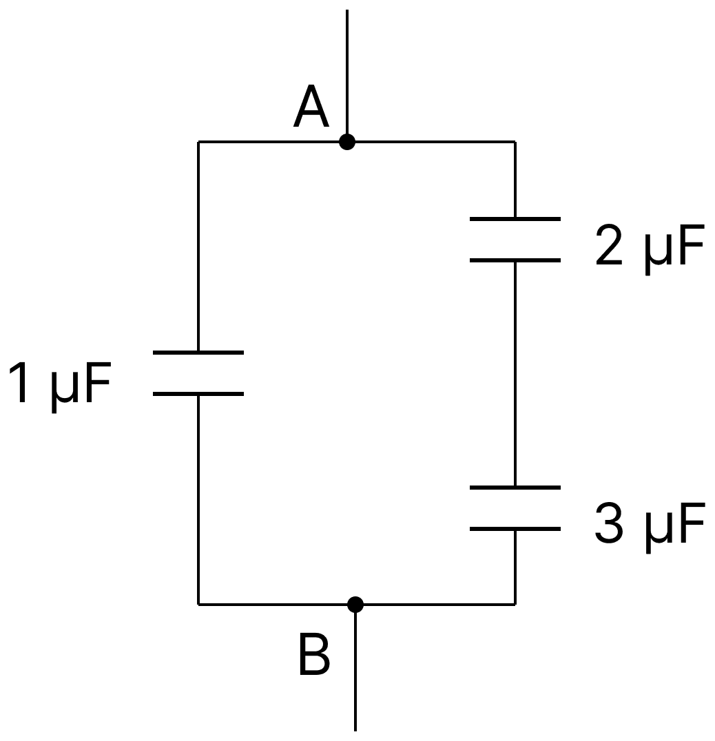
In the given combination of capacitors, the PD between the points A and B is 40 V. Find the effective capacitance between these points and charge on each capacitor. Capacitors Dielectrics, Nootan Physics Solutions ICS Class 12

Answer

Given,

  • Capacitances 2 µF, 3 µF and 1 µF
  • Potential difference between A and B, V = 40 V

From the figure the 2 µF and 3 µF capacitors are in series, and this series branch is in parallel with the 1 µF capacitor.

For the series branch,

C′=2×32+3C′=1.2 μF\text C' = \dfrac{2 \times 3}{2 + 3} \\[1em] \text C' = 1.2\ \mu\text F

The effective capacitance between A and B is

Ceq=C′+1Ceq=1.2+1Ceq=2.2 μF\text C_\text{eq} = \text C' + 1 \\[1em] \text C_\text{eq} = 1.2 + 1 \\[1em] \text C_\text{eq} = 2.2\ \mu\text F

Charge on the 1 µF capacitor : it has the full 40 V across it,

Q=(1)(40)Q=40 μC\text Q = (1)(40) \\[1em] \text Q = 40\ \mu\text C

Charge on the series branch : the same charge flows through both capacitors of this branch,

Q′=C′VQ′=(1.2)(40)Q′=48 μC\text Q' = \text C'\text V \\[1em] \text Q' = (1.2)(40) \\[1em] \text Q' = 48\ \mu\text C

Hence, the effective capacitance is 2.2 µF; the charges on the 2 µF, 3 µF and 1 µF capacitors are 48 µC, 48 µC and 40 µC respectively.

Question 36

Calculate the capacitance C in the given figure. The equivalent capacitance of the combination between P and Q is 30 µF.
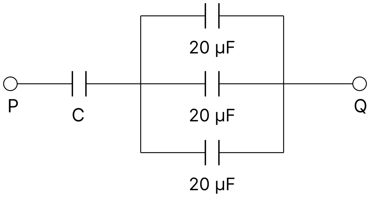
Calculate the capacitance C in the given figure. The equivalent capacitance of the combination between P and Q is 30 µF. Capacitors Dielectrics, Nootan Physics Solutions ICS Class 12

Answer

Given,

  • Three capacitors of 20 µF each, joined in parallel
  • Equivalent capacitance between P and Q, Ceq = 30 µF

The three 20 µF capacitors are in parallel, so

C′=20+20+20C′=60 μF\text C' = 20 + 20 + 20 \\[1em] \text C' = 60\ \mu\text F

The capacitance C is in series with this combination, hence

1Ceq=1C+1C′\dfrac{1}{\text C_\text{eq}} = \dfrac{1}{\text C} + \dfrac{1}{\text C'}

Substituting the values,

130=1C+1601C=130−1601C=2−1601C=160C=60 μF\dfrac{1}{30} = \dfrac{1}{\text C} + \dfrac{1}{60} \\[1em] \dfrac{1}{\text C} = \dfrac{1}{30} - \dfrac{1}{60} \\[1em] \dfrac{1}{\text C} = \dfrac{2 - 1}{60} \\[1em] \dfrac{1}{\text C} = \dfrac{1}{60} \\[1em] \text C = 60\ \mu\text F

Hence, the capacitance C is 60 µF.

Question 37

Calculate the equivalent capacitance between the points A and B in the given combination.

Calculate the equivalent capacitance between the points A and B in the given combination. Capacitors Dielectrics, Nootan Physics Solutions ICS Class 12

Answer

Given,

  • Capacitances 5 µF, 10 µF, 15 µF and 30 µF

Let the junctions along the row be numbered 1, 2 and 3, the 5 µF lying between A and node 1, the 10 µF between nodes 1 and 2, the 15 µF between nodes 2 and 3, and the 30 µF between node 3 and B.

From the figure, the upper connecting wire joins A to node 2, and the lower connecting wire joins node 1 to node 3. Hence
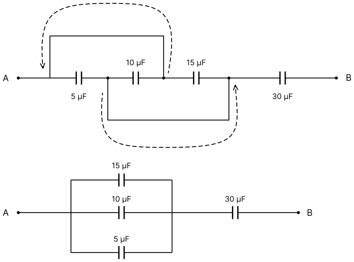
A≡node 2,node 1≡node 3\text A \equiv \text{node 2}, \qquad \text{node 1} \equiv \text{node 3}

Calculate the equivalent capacitance between the points A and B in the given combination. Capacitors Dielectrics, Nootan Physics Solutions ICS Class 12

Therefore the 5 µF, the 10 µF and the 15 µF capacitors all lie between the same pair of points, that is, they are in parallel :

C′=5+10+15C′=30 μF\text C' = 5 + 10 + 15 \\[1em] \text C' = 30\ \mu\text F

This combination is in series with the 30 µF capacitor,

Ceq=30×3030+30Ceq=15 μF\text C_\text{eq} = \dfrac{30 \times 30}{30 + 30} \\[1em] \text C_\text{eq} = 15\ \mu\text F

Hence, the equivalent capacitance between A and B is 15 µF.

Question 38

In the given network, calculate (i) equivalent capacitance between A and B, (ii) if a voltage of 150 V is applied between A and B calculate the PD between the plates of 6 µF capacitance.
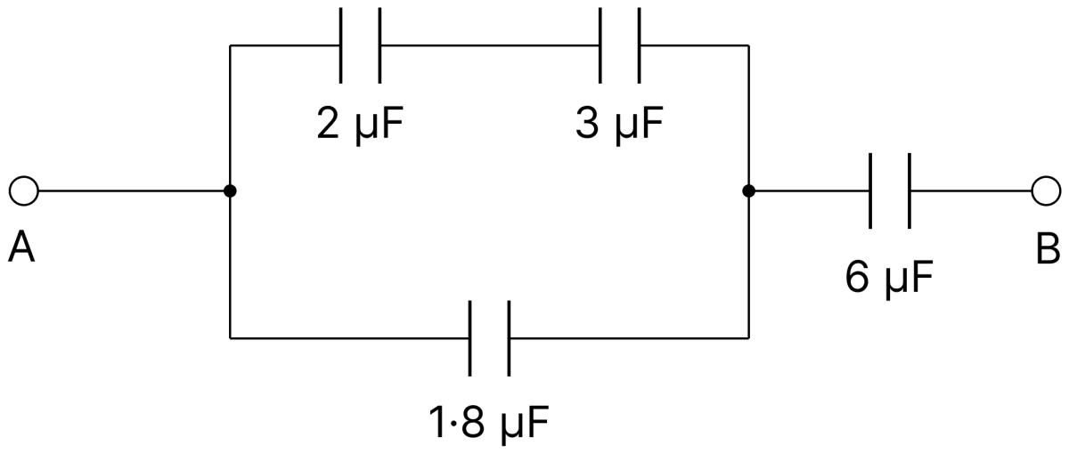
In the given network, calculate (i) equivalent capacitance between A and B, (ii) if a voltage of 150 V is applied between A and B calculate the PD between the plates of 6 µF capacitance. Capacitors Dielectrics, Nootan Physics Solutions ICS Class 12

Answer

Given,

  • Capacitances 2 µF, 3 µF, 1.8 µF and 6 µF
  • Applied voltage, V = 150 V

(i) The 2 µF and 3 µF capacitors are in series,

C′=2×32+3C′=1.2 μF\text C' = \dfrac{2 \times 3}{2 + 3} \\[1em] \text C' = 1.2\ \mu\text F

This is in parallel with the 1.8 µF capacitor,

C′′=1.2+1.8C′′=3 μF\text C'' = 1.2 + 1.8 \\[1em] \text C'' = 3\ \mu\text F

This combination is in series with the 6 µF capacitor,

Ceq=3×63+6Ceq=2 μF\text C_\text{eq} = \dfrac{3 \times 6}{3 + 6} \\[1em] \text C_\text{eq} = 2\ \mu\text F

(ii) The total charge drawn is

Q=CeqVQ=(2)(150)Q=300 μC\text Q = \text C_\text{eq}\text V \\[1em] \text Q = (2)(150) \\[1em] \text Q = 300\ \mu\text C

Since the 6 µF capacitor is in series with the rest, it carries this whole charge. Hence

V6=Q6V6=3006V6=50 V\text V_6 = \dfrac{\text Q}{6} \\[1em] \text V_6 = \dfrac{300}{6} \\[1em] \text V_6 = 50\ \text V

Hence, the equivalent capacitance is 2 µF and the PD across the 6 µF capacitor is 50 V.

Question 39

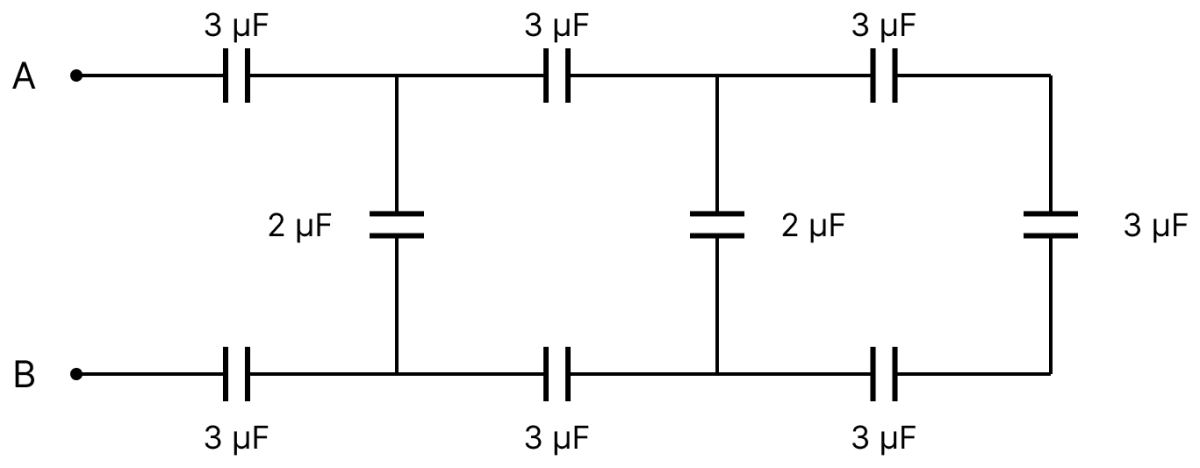
Calculate the equivalent capacitance between the points A and B in the given circuit. If 100 V PD is established between A and B then what will be the charge on the capacitor closest to?
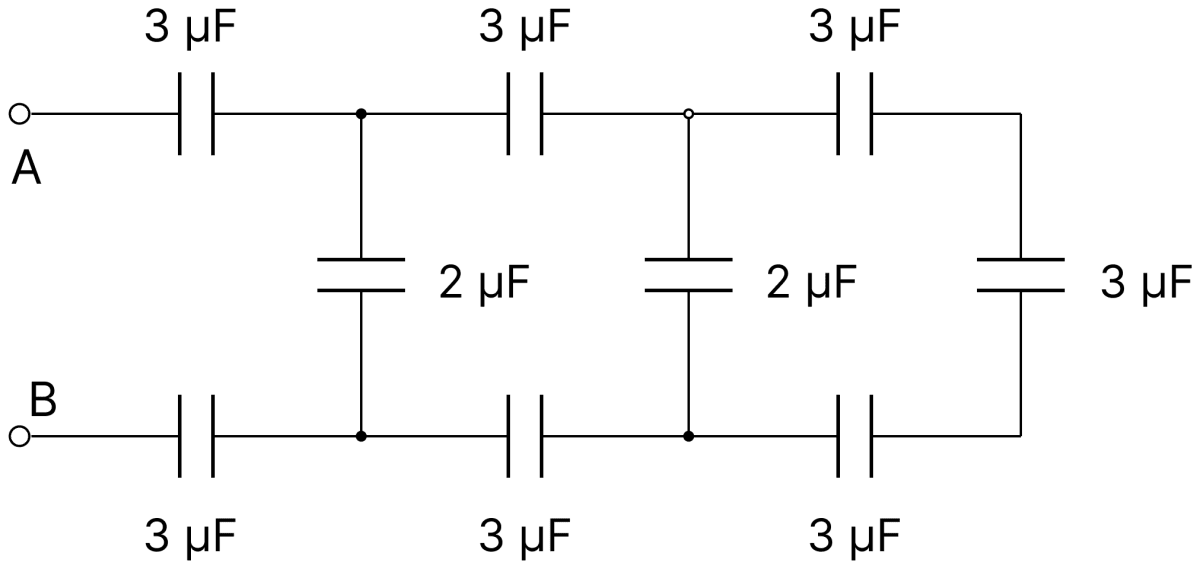
Calculate the equivalent capacitance between the points A and B in the given circuit. If 100 V PD is established between A and B then what will be the charge on the capacitor closest to? Capacitors Dielectrics, Nootan Physics Solutions ICS Class 12

Answer

Given,

  • Six capacitors of 3 µF in the two horizontal rows, two capacitors of 2 µF as the cross links and one 3 µF at the far end
  • Potential difference between A and B, V = 100 V

The network is a ladder, and it is reduced from the far end towards A and B.

Last section : the end 3 µF together with the last 3 µF of the upper row and the last 3 µF of the lower row form a series combination,
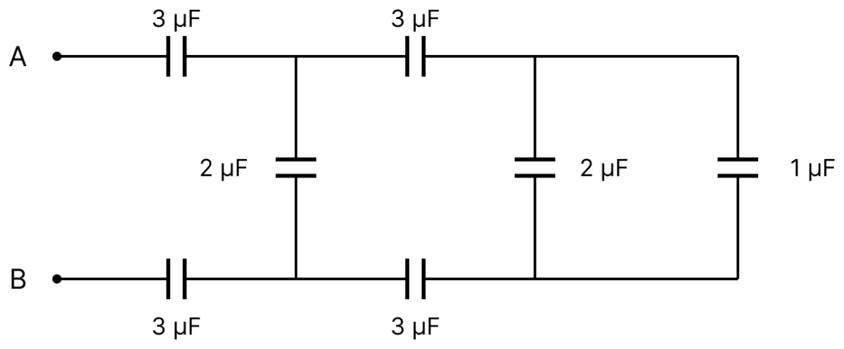
Calculate the equivalent capacitance between the points A and B in the given circuit. If 100 V PD is established between A and B then what will be the charge on the capacitor closest to? Capacitors Dielectrics, Nootan Physics Solutions ICS Class 12

1C=13+13+131C=1C=1 μF\dfrac{1}{\text C} = \dfrac{1}{3} + \dfrac{1}{3} + \dfrac{1}{3} \\[1em] \dfrac{1}{\text C} = 1 \\[1em] \text C = 1\ \mu\text F

Calculate the equivalent capacitance between the points A and B in the given circuit. If 100 V PD is established between A and B then what will be the charge on the capacitor closest to? Capacitors Dielectrics, Nootan Physics Solutions ICS Class 12

This is in parallel with the second 2 µF cross link,
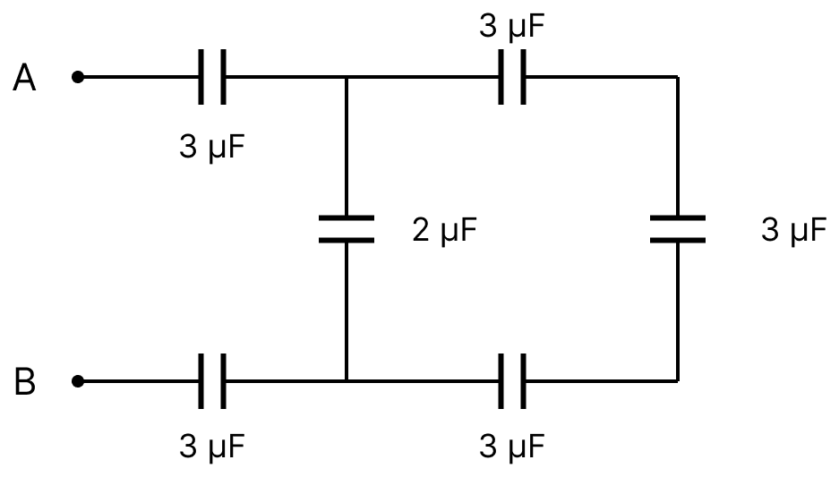
C=1+2C=3 μF\text C = 1 + 2 \\[1em] \text C = 3\ \mu\text F

Calculate the equivalent capacitance between the points A and B in the given circuit. If 100 V PD is established between A and B then what will be the charge on the capacitor closest to? Capacitors Dielectrics, Nootan Physics Solutions ICS Class 12

Middle section : this 3 µF is in series with the middle 3 µF of each row,
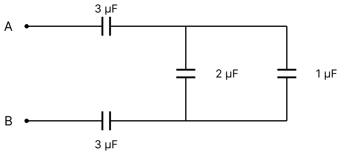
1C=13+13+131C=1C=1 μF\dfrac{1}{\text C} = \dfrac{1}{3} + \dfrac{1}{3} + \dfrac{1}{3} \\[1em] \dfrac{1}{\text C} = 1 \\[1em] \text C = 1\ \mu\text F

Calculate the equivalent capacitance between the points A and B in the given circuit. If 100 V PD is established between A and B then what will be the charge on the capacitor closest to? Capacitors Dielectrics, Nootan Physics Solutions ICS Class 12

and in parallel with the first 2 µF cross link,
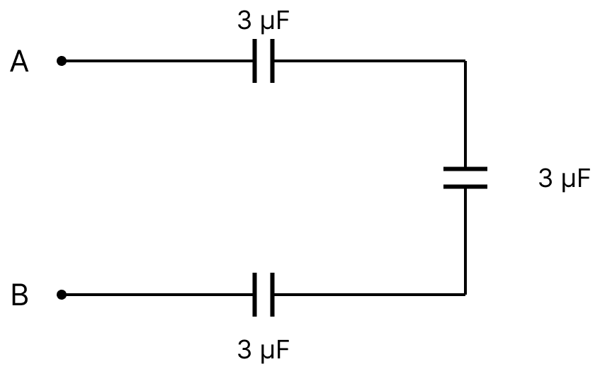
C=1+2C=3 μF\text C = 1 + 2 \\[1em] \text C = 3\ \mu\text F

Calculate the equivalent capacitance between the points A and B in the given circuit. If 100 V PD is established between A and B then what will be the charge on the capacitor closest to? Capacitors Dielectrics, Nootan Physics Solutions ICS Class 12

First section : this 3 µF is in series with the first 3 µF of each row,

1Ceq=13+13+131Ceq=1Ceq=1 μF\dfrac{1}{\text C_\text{eq}} = \dfrac{1}{3} + \dfrac{1}{3} + \dfrac{1}{3} \\[1em] \dfrac{1}{\text C_\text{eq}} = 1 \\[1em] \text C_\text{eq} = 1\ \mu\text F

The charge drawn from the supply is

Q=CeqVQ=(1)(100)Q=100 μC\text Q = \text C_\text{eq}\text V \\[1em] \text Q = (1)(100) \\[1em] \text Q = 100\ \mu\text C

Since the capacitors nearest to A and B are in series with the whole of the remaining network, this entire charge resides on them.

Hence, the equivalent capacitance is 1 µF and the charge on the capacitor closest to A (or to B) is 100 µC.

Note: The last sentence of the question is incomplete in the textbook; it is taken to mean the capacitor closest to the point A.

Question 40

Four capacitors of equal capacitances are joined in series with a battery of 10 V. The middle point B is connected to the earth. What will be the potentials of the points A and C?
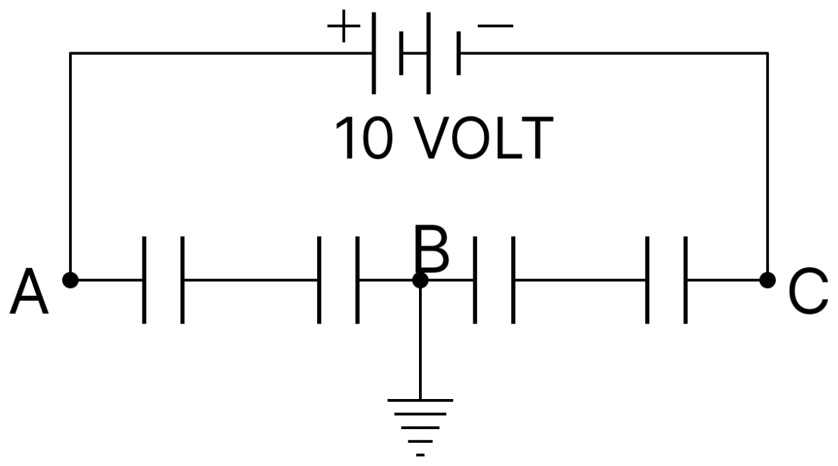
Four capacitors of equal capacitances are joined in series with a battery of 10 V. The middle point B is connected to the earth. What will be the potentials of the points A and C? Capacitors Dielectrics, Nootan Physics Solutions ICS Class 12

Answer

Given,

  • Four capacitors of equal capacitance joined in series
  • EMF of the battery, VA − VC = 10 V
  • The middle point B is earthed, so VB = 0

Two equal capacitors lie between A and B, and two equal capacitors lie between B and C. Since the capacitances on either side of B are equal and each carries the same charge, the potential differences on the two sides are equal in magnitude,

VA−VB=VB−VCVA+VC=2VB=0\text V_A - \text V_B = \text V_B - \text V_C \\[1em] \text V_A + \text V_C = 2\text V_B = 0

Also, from the battery,

VA−VC=10 V\text V_A - \text V_C = 10\ \text V

Solving the two equations,

VA=+5 VandVC=−5 V\text V_A = + 5\ \text V \qquad \text{and} \qquad \text V_C = - 5\ \text V

Hence, the potentials of A and C are + 5 volt and − 5 volt respectively.

Question 41

A parallel-plate capacitor with no dielectric has a capacitance of 0.5 µF. The space between the plates is then filled with equal amounts of two dielectrics of dielectric constants 2 and 3 in the two arrangements as shown one by one. Find the ratio of capacitances CI and CII.
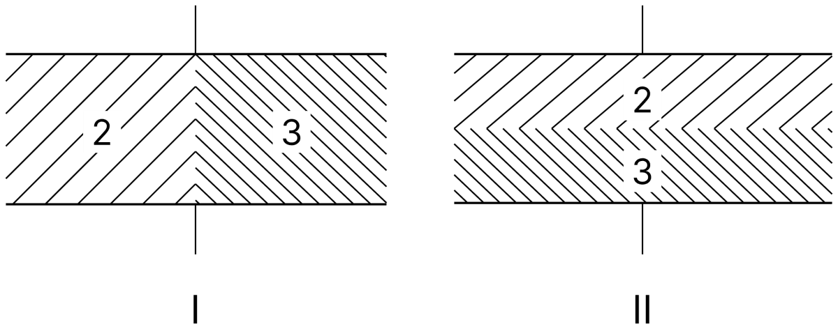
A parallel-plate capacitor with no dielectric has a capacitance of 0.5 µF. The space between the plates is then filled with equal amounts of two dielectrics of dielectric constants 2 and 3 in the two arrangements as shown one by one. Find the ratio of capacitances C I and C II. Capacitors Dielectrics, Nootan Physics Solutions ICS Class 12

Answer

Given,

  • Capacitance without dielectric, C0 = ε0A/d = 0.5 µF
  • Dielectric constants, K1 = 2 and K2 = 3

Arrangement I : The two dielectrics occupy the two halves of the plate area, each of area A/2 with the full separation d. The two portions behave as two capacitors in parallel,

CI=K1ϵ0(A/2)d+K2ϵ0(A/2)dCI=ϵ0A2d(K1+K2)CI=C02(2+3)CI=2.5 C0\text C_I = \dfrac{\text K_1 \epsilon_0 (\text A/2)}{\text d} + \dfrac{\text K_2 \epsilon_0 (\text A/2)}{\text d} \\[1em] \text C_I = \dfrac{\epsilon_0 \text A}{2\text d}(\text K_1 + \text K_2) \\[1em] \text C_I = \dfrac{\text C_0}{2}(2 + 3) \\[1em] \text C_I = 2.5\thinspace\text C_0

Arrangement II : The two dielectrics are stacked one above the other, each of thickness d/2 with the full area A. They behave as two capacitors in series,

C1=2K1ϵ0Ad,C2=2K2ϵ0AdCII=C1C2C1+C2CII=2ϵ0Ad(K1K2K1+K2)CII=2C0(2×32+3)CII=2.4 C0\text C_1 = \dfrac{2\text K_1 \epsilon_0 \text A}{\text d}, \qquad \text C_2 = \dfrac{2\text K_2 \epsilon_0 \text A}{\text d} \\[1em] \text C_\text{II} = \dfrac{\text C_1 \text C_2}{\text C_1 + \text C_2} \\[1em] \text C_\text{II} = \dfrac{2\epsilon_0 \text A}{\text d}\left(\dfrac{\text K_1 \text K_2}{\text K_1 + \text K_2}\right) \\[1em] \text C_\text{II} = 2\text C_0\left(\dfrac{2 \times 3}{2 + 3}\right) \\[1em] \text C_\text{II} = 2.4\thinspace\text C_0

Therefore

CICII=2.5 C02.4 C0CICII=2524\dfrac{\text C_I}{\text C_\text{II}} = \dfrac{2.5\thinspace\text C_0}{2.4\thinspace\text C_0} \\[1em] \dfrac{\text C_I}{\text C_\text{II}} = \dfrac{25}{24}

Hence, CI : CII = 25 : 24.

Question 42

As shown in figure, a dielectric substance of dielectric constant K is inserted in half of the portion between the plates of a parallel-plate capacitor. If its initial capacitance is C, then what will be the new capacitance?
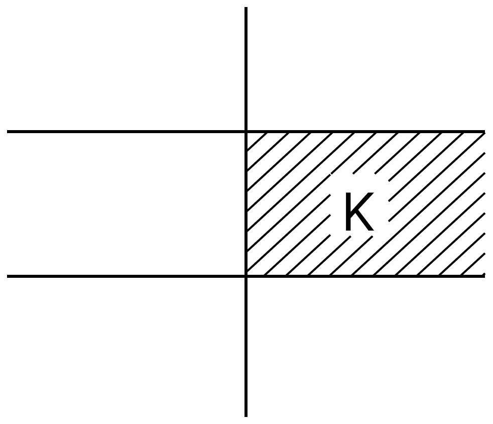
As shown in figure, a dielectric substance of dielectric constant K is inserted in half of the portion between the plates of a parallel-plate capacitor. If its initial capacitance is C, then what will be the new capacitance? Capacitors Dielectrics, Nootan Physics Solutions ICS Class 12

Answer

Given,

  • Initial capacitance of the air capacitor, C = ε0A/d
  • The dielectric of constant K fills half the plate area

The arrangement is equivalent to two capacitors joined in parallel, each of plate area A/2 and separation d, one with air and the other with the dielectric.

C1=ϵ0(A/2)dC1=C2C2=Kϵ0(A/2)dC2=KC2\text C_1 = \dfrac{\epsilon_0 (\text A/2)}{\text d} \\[1em] \text C_1 = \dfrac{\text C}{2} \\[1em] \text C_2 = \dfrac{\text K \epsilon_0 (\text A/2)}{\text d} \\[1em] \text C_2 = \dfrac{\text{KC}}{2}

Hence the new capacitance is

C′=C1+C2C′=C2+KC2C′=12C(1+K)\text C' = \text C_1 + \text C_2 \\[1em] \text C' = \dfrac{\text C}{2} + \dfrac{\text{KC}}{2} \\[1em] \text C' = \dfrac{1}{2}\text C(1 + \text K)

Hence, the new capacitance is 12C(1+K)\dfrac{1}{2}\text C(1 + \text K).

Question 43

Figure shows charge (q) versus voltage (V) graph for series and parallel combination of two given capacitors. Find the value of the capacitance of the given capacitors.
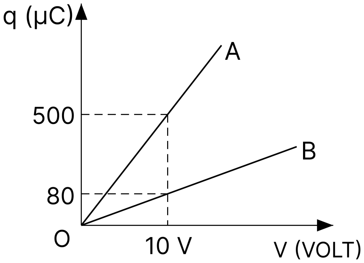
Figure shows charge (q) *versus* voltage (V) graph for series and parallel combination of two given capacitors. Find the value of the capacitance of the given capacitors. Capacitors Dielectrics, Nootan Physics Solutions ICS Class 12

Answer

Given, from the graph,

  • For the line A : q = 500 µC at V = 10 V
  • For the line B : q = 80 µC at V = 10 V

The slope of a q–V line gives the capacitance, C = q/V. The line of greater slope corresponds to the parallel combination and the other to the series combination. Hence

Cp=50010Cp=50 μFCs=8010Cs=8 μF\text C_p = \dfrac{500}{10} \\[1em] \text C_p = 50\ \mu\text F \\[1em] \text C_s = \dfrac{80}{10} \\[1em] \text C_s = 8\ \mu\text F

Let the two capacitances be C1 and C2. Then

C1+C2=50…(i)C1C2C1+C2=8C1C2=8×50C1C2=400…(ii)\text C_1 + \text C_2 = 50 \qquad \dots(\text i) \\[1em] \dfrac{\text C_1 \text C_2}{\text C_1 + \text C_2} = 8 \\[1em] \text C_1 \text C_2 = 8 \times 50 \\[1em] \text C_1 \text C_2 = 400 \qquad \dots(\text{ii})

C1 and C2 are therefore the roots of

x2−50x+400=0x=50±2500−16002x=50±302x=40 or 10\text x^2 - 50\text x + 400 = 0 \\[1em] \text x = \dfrac{50 \pm \sqrt{2500 - 1600}}{2} \\[1em] \text x = \dfrac{50 \pm 30}{2} \\[1em] \text x = 40\ \text{or}\ 10

Hence, the capacitances of the two given capacitors are 40 µF and 10 µF.

Question 44

The two plates of a parallel plate capacitor are 4 mm apart. A slab of dielectric constant 3 and thickness 3 mm is introduced between the plates with its faces parallel to them. The distance between the plates is so adjusted that the capacitance of the capacitor becomes 23\dfrac{2}{3} rd of its original value. What is the new distance between the plates?

Answer

Given,

  • Original separation, d = 4 mm
  • Thickness of the slab, t = 3 mm
  • Dielectric constant, K = 3
  • New capacitance, C = 23\dfrac{2}{3} C0

The original capacitance is

C0=ϵ0A4\text C_0 = \dfrac{\epsilon_0 \text A}{4}

Let d' be the new separation. With the slab introduced,

C=ϵ0Ad′−t+tKC=ϵ0Ad′−3+33C=ϵ0Ad′−2\text C = \dfrac{\epsilon_0 \text A}{\text d' - \text t + \dfrac{\text t}{\text K}} \\[1em] \text C = \dfrac{\epsilon_0 \text A}{\text d' - 3 + \dfrac{3}{3}} \\[1em] \text C = \dfrac{\epsilon_0 \text A}{\text d' - 2}

Since C = 23\dfrac{2}{3} C0,

ϵ0Ad′−2=23(ϵ0A4)ϵ0Ad′−2=ϵ0A6d′−2=6d′=8 mm\dfrac{\epsilon_0 \text A}{\text d' - 2} = \dfrac{2}{3}\left(\dfrac{\epsilon_0 \text A}{4}\right) \\[1em] \dfrac{\epsilon_0 \text A}{\text d' - 2} = \dfrac{\epsilon_0 \text A}{6} \\[1em] \text d' - 2 = 6 \\[1em] \text d' = 8\ \text{mm}

Hence, the new distance between the plates is 8 mm.

Question 45

X and Y are two parallel plate capacitors having the same areas of plates and same separation between the plates. X has air between the plates and Y contains a dielectric medium εr = 4.
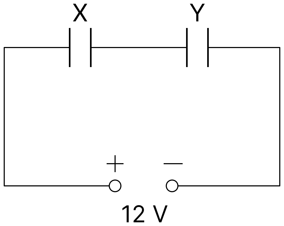
X and Y are two parallel plate capacitors having the same areas of plates and same separation between the plates. X has air between the plates and Y contains a dielectric medium ε r = 4. Capacitors Dielectrics, Nootan Physics Solutions ICS Class 12

(i) Calculate the capacitance of each capacitor if equivalent capacitance of the combination is 4 µF.

(ii) Calculate the potential difference between the plates of X and Y.

(iii) What is the ratio of electrostatic energy stored in X and Y?

Answer

Given,

  • X is an air capacitor, Y contains a dielectric of εr = 4
  • The two are joined in series across a 12 V battery
  • Equivalent capacitance, Ceq = 4 µF

(i) Since the plate areas and separations are equal,

CY=4 CX\text C_Y = 4\thinspace\text C_X

For the series combination,

Ceq=CXCYCX+CYCeq=CX(4CX)5CXCeq=4CX54=4CX5CX=5 μFCY=20 μF\text C_\text{eq} = \dfrac{\text C_X \text C_Y}{\text C_X + \text C_Y} \\[1em] \text C_\text{eq} = \dfrac{\text C_X(4\text C_X)}{5\text C_X} \\[1em] \text C_\text{eq} = \dfrac{4\text C_X}{5} \\[1em] 4 = \dfrac{4\text C_X}{5} \\[1em] \text C_X = 5\ \mu\text F \\[1em] \text C_Y = 20\ \mu\text F

(ii) In series both capacitors carry the same charge,

Q=CeqVQ=(4)(12)Q=48 μCVX=QCXVX=485VX=9.6 VVY=QCYVY=4820VY=2.4 V\text Q = \text C_\text{eq}\text V \\[1em] \text Q = (4)(12) \\[1em] \text Q = 48\ \mu\text C \\[1em] \text V_X = \dfrac{\text Q}{\text C_X} \\[1em] \text V_X = \dfrac{48}{5} \\[1em] \text V_X = 9.6\ \text V \\[1em] \text V_Y = \dfrac{\text Q}{\text C_Y} \\[1em] \text V_Y = \dfrac{48}{20} \\[1em] \text V_Y = 2.4\ \text V

(iii) For the same charge, U = Q2/2C, so

UXUY=CYCXUXUY=205UXUY=4\dfrac{\text U_X}{\text U_Y} = \dfrac{\text C_Y}{\text C_X} \\[1em] \dfrac{\text U_X}{\text U_Y} = \dfrac{20}{5} \\[1em] \dfrac{\text U_X}{\text U_Y} = 4

Hence, CX = 5 µF and CY = 20 µF; VX = 9.6 V and VY = 2.4 V; and UX : UY = 4 : 1.

Question 46

A system of capacitors connected as shown in the figure has total energy of 160 mJ stored in it. Obtain the value of the equivalent capacitance of this system and the value of Z.
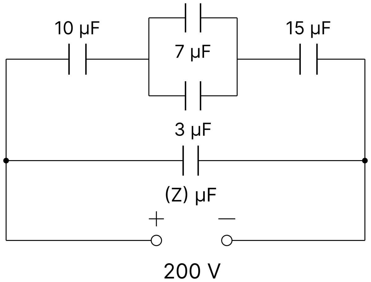
A system of capacitors connected as shown in the figure has total energy of 160 mJ stored in it. Obtain the value of the equivalent capacitance of this system and the value of Z. Capacitors Dielectrics, Nootan Physics Solutions ICS Class 12

Answer

Given,

  • Capacitors of 10 µF, 7 µF, 3 µF, 15 µF and Z µF
  • Applied voltage, V = 200 V
  • Total energy stored, U = 160 mJ = 0.16 J

Equivalent capacitance : From the energy stored,

U=12CeqV20.16=12Ceq(200)20.16=12Ceq(4×10⁴)Ceq=2×0.164×104Ceq=8×10⁻⁶ FCeq=8 μF\text U = \dfrac{1}{2}\text C_\text{eq}\text V^2 \\[1em] 0.16 = \dfrac{1}{2}\text C_\text{eq}(200)^2 \\[1em] 0.16 = \dfrac{1}{2}\text C_\text{eq}(4 \times 10^4) \\[1em] \text C_\text{eq} = \dfrac{2 \times 0.16}{4 \times 10^4} \\[1em] \text C_\text{eq} = 8 \times 10^{-6}\ \text F \\[1em] \text C_\text{eq} = 8\ \mu\text F

Value of Z : In the upper branch, the 7 µF and 3 µF capacitors are in parallel,

7+3=10 μF7 + 3 = 10\ \mu\text F

This is in series with the 10 µF and the 15 µF capacitors,

1C′=110+110+1151C′=3+3+2301C′=830C′=308C′=3.75 μF\dfrac{1}{\text C'} = \dfrac{1}{10} + \dfrac{1}{10} + \dfrac{1}{15} \\[1em] \dfrac{1}{\text C'} = \dfrac{3 + 3 + 2}{30} \\[1em] \dfrac{1}{\text C'} = \dfrac{8}{30} \\[1em] \text C' = \dfrac{30}{8} \\[1em] \text C' = 3.75\ \mu\text F

The capacitor Z is in parallel with this branch, so

Ceq=C′+Z8=3.75+ZZ=4.25 μF\text C_\text{eq} = \text C' + \text Z \\[1em] 8 = 3.75 + \text Z \\[1em] \text Z = 4.25\ \mu\text F

Hence, the equivalent capacitance is 8 µF and Z = 4.25 µF.

Question 47

Find the capacitance of an infinite circuit formed by the repetition of the same link consisting of two identical capacitors, each with capacitance C.
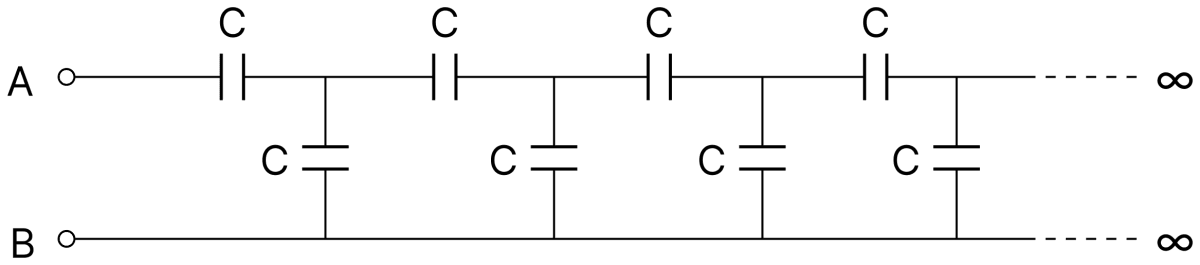
Find the capacitance of an infinite circuit formed by the repetition of the same link consisting of two identical capacitors, each with capacitance C. Capacitors Dielectrics, Nootan Physics Solutions ICS Class 12

Answer

Given,

  • Each capacitor of the repeating link has capacitance C
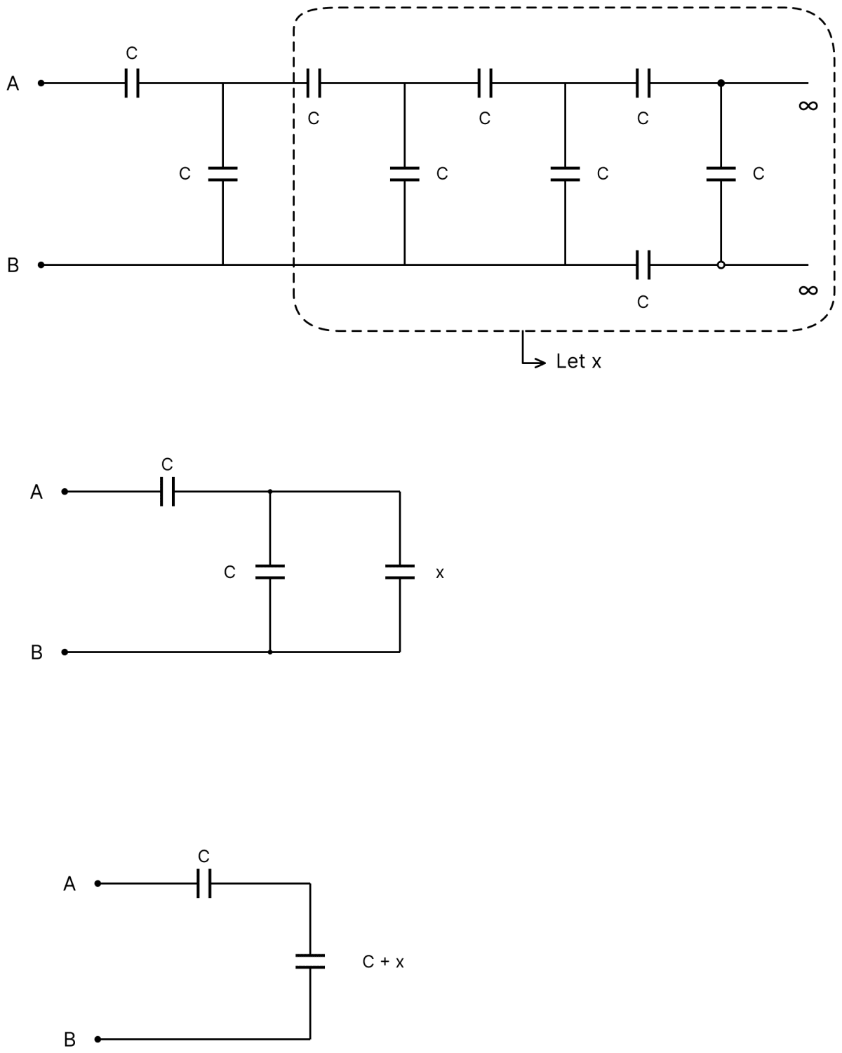
Find the capacitance of an infinite circuit formed by the repetition of the same link consisting of two identical capacitors, each with capacitance C. Capacitors Dielectrics, Nootan Physics Solutions ICS Class 12

Let the capacitance of the whole infinite network between A and B be x. Since the network is infinite, removing the first link leaves a network which is again identical to the original one, of capacitance x.

Hence the arrangement is : one capacitor C in series with the parallel combination of the shunt capacitor C and the remaining network x. Therefore

1x=1C+1C+x1x=(C+x)+CC(C+x)1x=2C+xC(C+x)\dfrac{1}{\text x} = \dfrac{1}{\text C} + \dfrac{1}{\text C + \text x} \\[1em] \dfrac{1}{\text x} = \dfrac{(\text C + \text x) + \text C}{\text C(\text C + \text x)} \\[1em] \dfrac{1}{\text x} = \dfrac{2\text C + \text x}{\text C(\text C + \text x)}

Cross-multiplying,

C(C+x)=x(2C+x)C2+Cx=2Cx+x2x2+Cx−C2=0\text C(\text C + \text x) = \text x(2\text C + \text x) \\[1em] \text C^2 + \text{Cx} = 2\text{Cx} + \text x^2 \\[1em] \text x^2 + \text{Cx} - \text C^2 = 0

Solving this quadratic and retaining the positive root,

x=−C+C2+4C22x=(5−1)C2\text x = \dfrac{-\text C + \sqrt{\text C^2 + 4\text C^2}}{2} \\[1em] \text x = \dfrac{(\sqrt{5} - 1)\text C}{2}

Hence, the capacitance of the infinite circuit is (5−1)2C\dfrac{(\sqrt{5} - 1)}{2}\text C.

Question 48

Find equivalent capacitance between P and Q in the following combinations; where each plate has plate area A and distance between neighbouring plates is d.
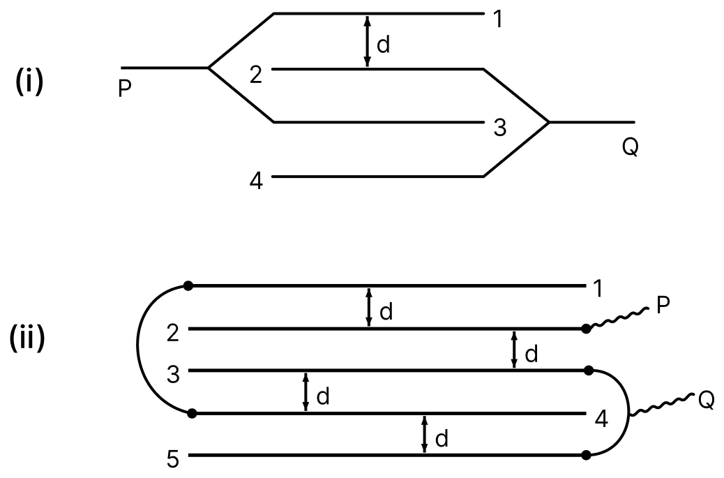
Find equivalent capacitance between P and Q in the following combinations; where each plate has plate area A and distance between neighbouring plates is d. 1, 2, 3 and 4 are the parallel plates of same area. Capacitors Dielectrics, Nootan Physics Solutions ICS Class 12

1, 2, 3 and 4 are the parallel plates of same area.

Answer

Given,

  • Area of each plate = A, distance between neighbouring plates = d
  • Capacitance of each gap, C0 = ε0A/d

(i) From the figure the plates 2 and 4 are joined to P, while the plates 1 and 3 are joined to Q. The three gaps 1–2, 2–3 and 3–4 therefore all lie between P and Q, that is, they are in parallel. Hence

CPQ=3C0CPQ=3ϵ0Ad\text C_\text{PQ} = 3\text C_0 \\[1em] \text C_\text{PQ} = \dfrac{3\epsilon_0 \text A}{\text d}

(ii) Here there are five plates and four gaps. From the figure the plates 1 and 3 are joined to P, the plate 4 is joined to Q, and the plates 2 and 5 are joined together to form a common node, say D.

The gaps then give :

  • gap 1–2 : between P and D, capacitance C0
  • gap 2–3 : between D and P, capacitance C0
  • gap 3–4 : between P and Q, capacitance C0
  • gap 4–5 : between Q and D, capacitance C0

The first two are in parallel between P and D, giving 2C0. This is in series with the gap 4–5 between D and Q,

2C0×C02C0+C0=2C03\dfrac{2\text C_0 \times \text C_0}{2\text C_0 + \text C_0} = \dfrac{2\text C_0}{3}

This path is in parallel with the gap 3–4, which lies directly between P and Q,

CPQ=C0+2C03CPQ=5C03CPQ=53ϵ0Ad\text C_\text{PQ} = \text C_0 + \dfrac{2\text C_0}{3} \\[1em] \text C_\text{PQ} = \dfrac{5\text C_0}{3} \\[1em] \text C_\text{PQ} = \dfrac{5}{3}\dfrac{\epsilon_0 \text A}{\text d}

Hence, (i) 3ϵ0Ad\dfrac{3\epsilon_0 \text A}{\text d} and (ii) 53ϵ0Ad\dfrac{5}{3}\dfrac{\epsilon_0 \text A}{\text d}.

Question 49

Find the equivalent capacitance between A and B in each case.
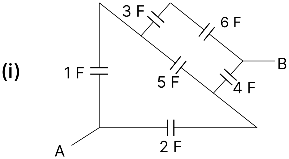
Find the equivalent capacitance between A and B in each case. Capacitors Dielectrics, Nootan Physics Solutions ICS Class 12
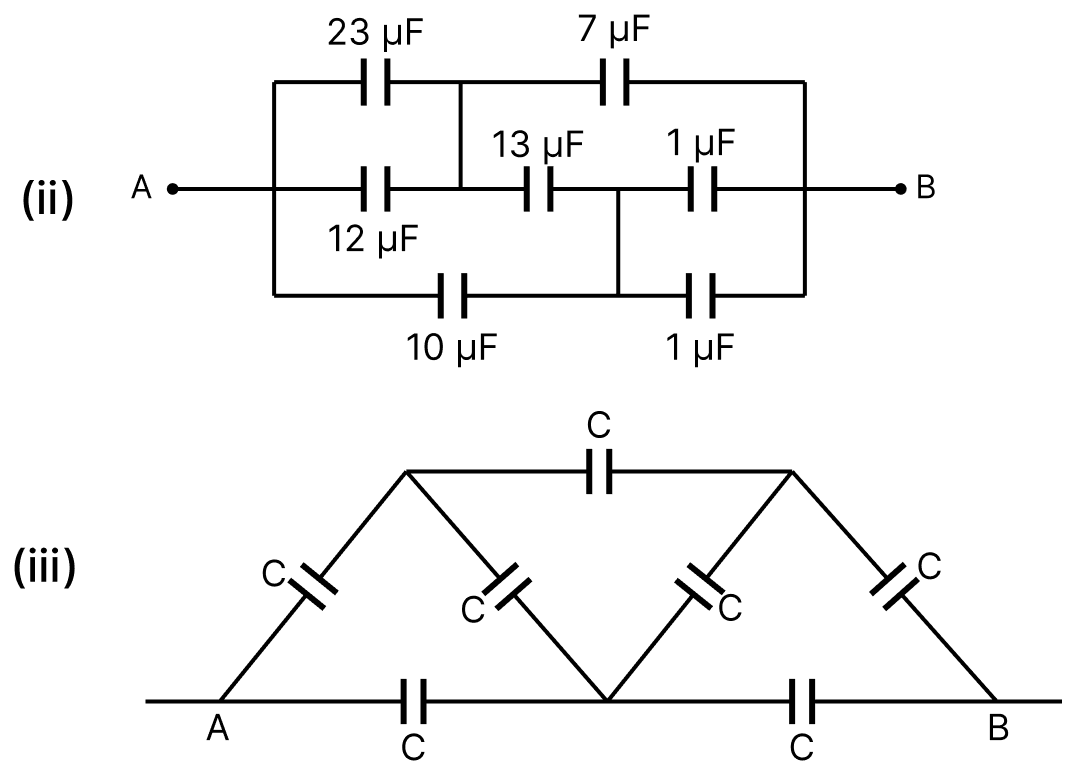

Answer

(i)

Given,

  • Capacitances 1 F, 2 F, 3 F, 4 F, 5 F and 6 F joined as shown

Let T be the top node, at which the 1 F capacitor, the 5 F capacitor and the upper branch meet, and J the node on the lower right wire, at which the 2 F, the 5 F and the 4 F capacitors meet.

Simplifying the upper branch : the 3 F and 6 F capacitors are in series,
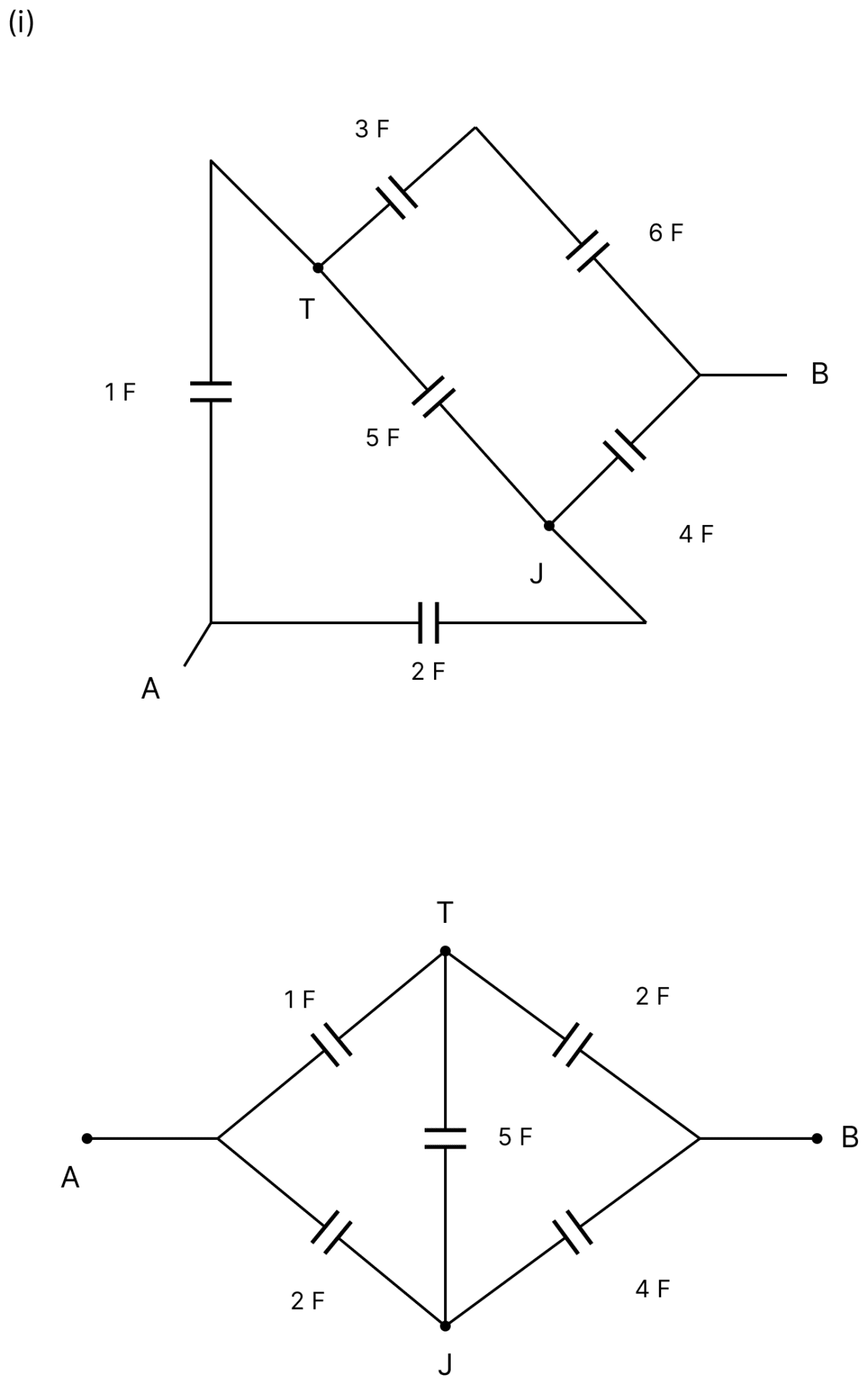
CTB=3×63+6CTB=189CTB=2 F\text C_\text{TB} = \dfrac{3 \times 6}{3 + 6} \\[1em] \text C_\text{TB} = \dfrac{18}{9} \\[1em] \text C_\text{TB} = 2\ \text F

Find the equivalent capacitance between A and B in each case. Capacitors Dielectrics, Nootan Physics Solutions ICS Class 12

Testing the balance : the network is now a Wheatstone bridge with the 5 F capacitor as the bridge arm. Comparing the ratios of the arms,

CATCTB=12CAJCJB=24CAJCJB=12\dfrac{\text C_\text{AT}}{\text C_\text{TB}} = \dfrac{1}{2} \\[1em] \dfrac{\text C_\text{AJ}}{\text C_\text{JB}} = \dfrac{2}{4} \\[1em] \dfrac{\text C_\text{AJ}}{\text C_\text{JB}} = \dfrac{1}{2}

The two ratios are equal, so the bridge is balanced. Hence the nodes T and J are at the same potential, no charge flows through the 5 F capacitor, and it may be removed.

Reducing the remaining branches : two series branches are left between A and B,

Ctop=1×21+2Ctop=23 FCbottom=2×42+4Cbottom=86Cbottom=43 F\text C_\text{top} = \dfrac{1 \times 2}{1 + 2} \\[1em] \text C_\text{top} = \dfrac{2}{3}\ \text F \\[1em] \text C_\text{bottom} = \dfrac{2 \times 4}{2 + 4} \\[1em] \text C_\text{bottom} = \dfrac{8}{6} \\[1em] \text C_\text{bottom} = \dfrac{4}{3}\ \text F

These are in parallel, hence

CAB=23+43CAB=63CAB=2 F\text C_\text{AB} = \dfrac{2}{3} + \dfrac{4}{3} \\[1em] \text C_\text{AB} = \dfrac{6}{3} \\[1em] \text C_\text{AB} = 2\ \text F

Hence, the equivalent capacitance between A and B is 2 F.

(ii)

Given,

  • Capacitances 23 µF, 12 µF, 7 µF, 13 µF, 10 µF and two of 1 µF joined as shown
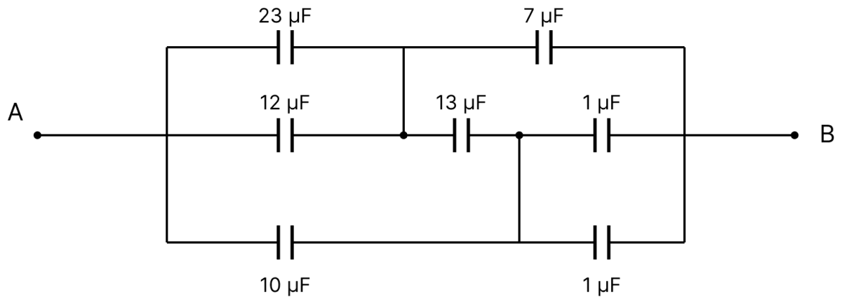
Find the equivalent capacitance between A and B in each case. Capacitors Dielectrics, Nootan Physics Solutions ICS Class 12

Combining the parallel capacitors : the 23 µF and 12 µF capacitors lie between the same pair of nodes, and so do the two 1 µF capacitors. Hence

Cleft=23+12Cleft=35 μFCright=1+1Cright=2 μF\text C_\text{left} = 23 + 12 \\[1em] \text C_\text{left} = 35\ \mu\text F \\[1em] \text C_\text{right} = 1 + 1 \\[1em] \text C_\text{right} = 2\ \mu\text F

Redrawing as a bridge : the network becomes a Wheatstone bridge with the 13 µF capacitor in the central branch, the four arms being
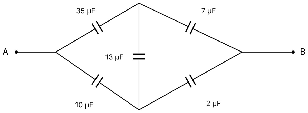
Find the equivalent capacitance between A and B in each case. Capacitors Dielectrics, Nootan Physics Solutions ICS Class 12

35 μF,7 μF,10 μF,2 μF35\ \mu\text F, \qquad 7\ \mu\text F, \qquad 10\ \mu\text F, \qquad 2\ \mu\text F

Testing the balance :

357=5102=5\dfrac{35}{7} = 5 \\[1em] \dfrac{10}{2} = 5

The two ratios are equal, so the bridge is balanced. The nodes on either side of the 13 µF capacitor are at the same potential, no charge flows through it, and it may be removed.

Reducing the remaining branches :

Ctop=35×735+7Ctop=24542Ctop=356 μFCbottom=10×210+2Cbottom=2012Cbottom=106 μF\text C_\text{top} = \dfrac{35 \times 7}{35 + 7} \\[1em] \text C_\text{top} = \dfrac{245}{42} \\[1em] \text C_\text{top} = \dfrac{35}{6}\ \mu\text F \\[1em] \text C_\text{bottom} = \dfrac{10 \times 2}{10 + 2} \\[1em] \text C_\text{bottom} = \dfrac{20}{12} \\[1em] \text C_\text{bottom} = \dfrac{10}{6}\ \mu\text F

These are in parallel, hence

CAB=356+106CAB=456CAB=7.5 μF\text C_\text{AB} = \dfrac{35}{6} + \dfrac{10}{6} \\[1em] \text C_\text{AB} = \dfrac{45}{6} \\[1em] \text C_\text{AB} = 7.5\ \mu\text F

Hence, the equivalent capacitance between A and B is 7.5 µF.

(iii)

Given,

  • Seven identical capacitors, each of capacitance C, joined as shown

The capacitor joining the two upper nodes links the two halves of the network, so it cannot be reduced by series and parallel steps alone. It is solved by the potential method.
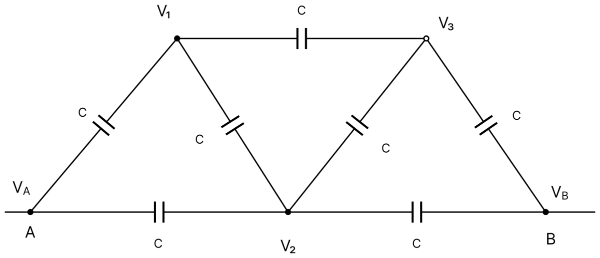
Find the equivalent capacitance between A and B in each case. Capacitors Dielectrics, Nootan Physics Solutions ICS Class 12

Setting up the node potentials : let a potential difference V be applied, so that

VA=V,VB=0\text V_A = \text V, \qquad \text V_B = 0

Let V1 be the potential of the top-left node, V2 that of the bottom-middle node and V3 that of the top-right node. The network is symmetrical about the vertical through the middle node, so

V2=V2,V3=V−V1\text V_2 = \dfrac{\text V}{2}, \qquad \text V_3 = \text V - \text V_1

Applying conservation of charge at the node V1 : this node is isolated, so the algebraic sum of the charges on the plates meeting there is zero. Its neighbours are A, the middle node and the top-right node, hence

(V1−V)C+(V1−V2)C+(V1−V3)C=0(\text V_1 - \text V)\text C + (\text V_1 - \text V_2)\text C + (\text V_1 - \text V_3)\text C = 0

Dividing by C and substituting the values of V2 and V3,

(V1−V)+(V1−V2)+[V1−(V−V1)]=04V1−5V2=0V1=58V(\text V_1 - \text V) + \left(\text V_1 - \dfrac{\text V}{2}\right) + \left[\text V_1 - (\text V - \text V_1)\right] = 0 \\[1em] 4\text V_1 - \dfrac{5\text V}{2} = 0 \\[1em] \text V_1 = \dfrac{5}{8}\text V

Finding the total charge : the charge drawn at the terminal A divides between the two capacitors joined to it, one going to the top-left node and the other to the middle node,

Q=(V−V1)C+(V−V2)C\text Q = (\text V - \text V_1)\text C + (\text V - \text V_2)\text C

Substituting the potentials,

Q=(V−58V)C+(V−12V)CQ=38CV+48CVQ=78CV\text Q = \left(\text V - \dfrac{5}{8}\text V\right)\text C + \left(\text V - \dfrac{1}{2}\text V\right)\text C \\[1em] \text Q = \dfrac{3}{8}\text{CV} + \dfrac{4}{8}\text{CV} \\[1em] \text Q = \dfrac{7}{8}\text{CV}

By definition the equivalent capacitance is

CAB=QVCAB=7C8\text C_\text{AB} = \dfrac{\text Q}{\text V} \\[1em] \text C_\text{AB} = \dfrac{7\text C}{8}

Hence, the equivalent capacitance between A and B is 7C8\dfrac{7\text C}{8}.

Question 50

The plates S and T of an uncharged parallel plate capacitor are connected across a battery. The battery is then disconnected and the charged plates are now connected in a system as shown in the figure. The system shown is in equilibrium. All the strings and spring are insulating and massless. Find the magnitude of charge of one of the capacitor plates (Area of each plate = A).
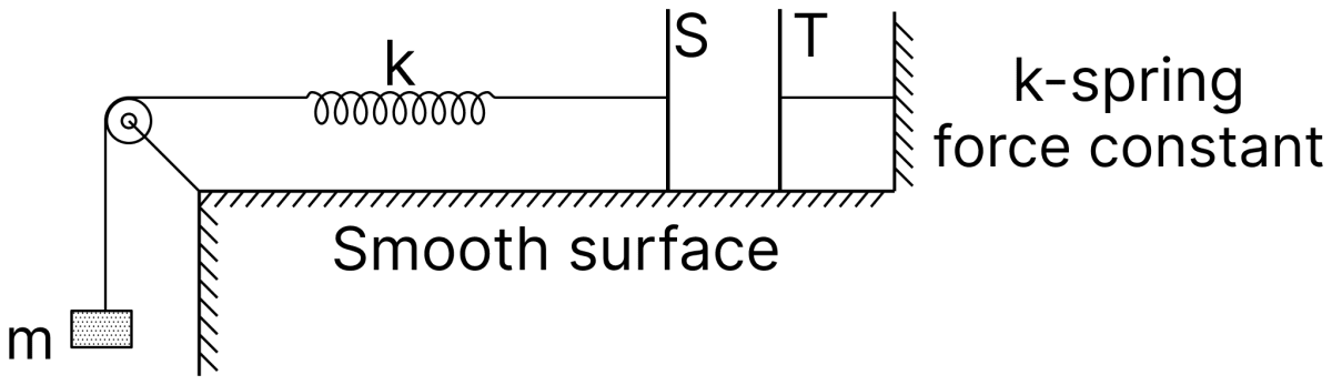
The plates S and T of an uncharged parallel plate capacitor are connected across a battery. The battery is then disconnected and the charged plates are now connected in a system as shown in the figure. The system shown is in equilibrium. All the strings and spring are insulating and massless. Find the magnitude of charge of one of the capacitor plates (Area of each plate = A). Capacitors Dielectrics, Nootan Physics Solutions ICS Class 12

Answer

Given,

  • Area of each plate = A
  • Mass hanging from the string = m
  • The system is in equilibrium and the surface is smooth

The two plates carry equal and opposite charges Q, so they attract each other. The force of attraction between the plates of a charged parallel-plate capacitor is

F=Q22ϵ0A\text F = \dfrac{\text Q^2}{2\epsilon_0 \text A}

Since the strings and the spring are massless and the surface is smooth, the tension in the string equals the weight of the hanging block,

T=mg\text T = \text{mg}

For the plate assembly to be in equilibrium, the electrostatic force of attraction between the plates must be balanced by this tension,

Q22ϵ0A=mgQ2=2 mg A ϵ0Q=2 mg A ϵ0\dfrac{\text Q^2}{2\epsilon_0 \text A} = \text{mg} \\[1em] \text Q^2 = 2\thinspace\text{mg}\thinspace\text A\thinspace\epsilon_0 \\[1em] \text Q = \sqrt{2\thinspace\text{mg}\thinspace\text A\thinspace\epsilon_0}

Hence, the magnitude of the charge on one of the plates is 2 mg A ϵ0\sqrt{2\thinspace\text{mg}\thinspace\text A\thinspace\epsilon_0}.

PrevNext