
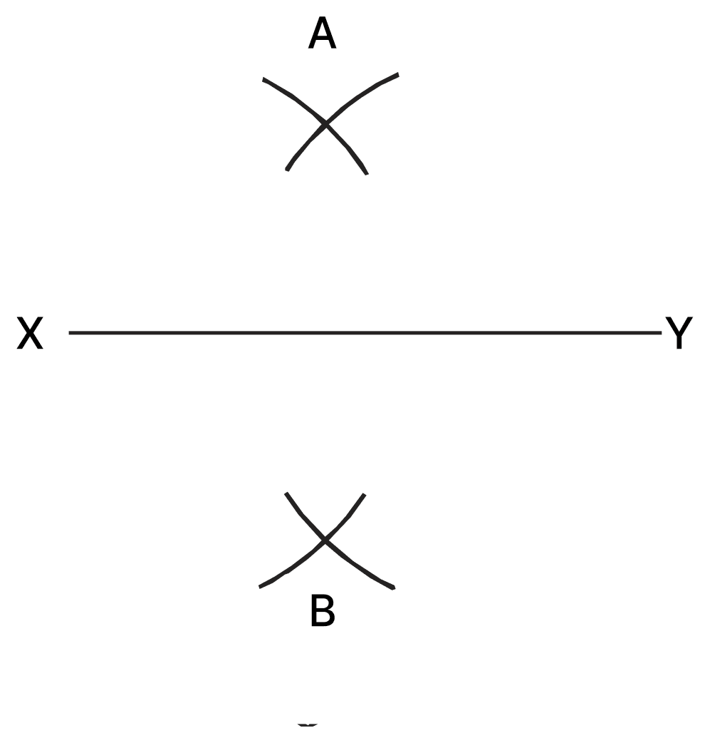
Will the line joining the two points at which the arcs meet, above and below XY, always be the perpendicular bisector of XY, i.e., when XY is of any length, and the arcs are drawn using a radius of any length?
Answer
Yes. This can be justified through congruence. The actual length of XY does not matter. The equal-radius arcs only need to be long enough to intersect above and below XY; for two distinct intersection points, the radius must be greater than half the length of XY.
Let XY be any line segment, and let A and B be the points such that
AX = AY = BX = BY.
Join AB, AX, AY, BX and BY. Let O be the point of intersection of AB and XY.
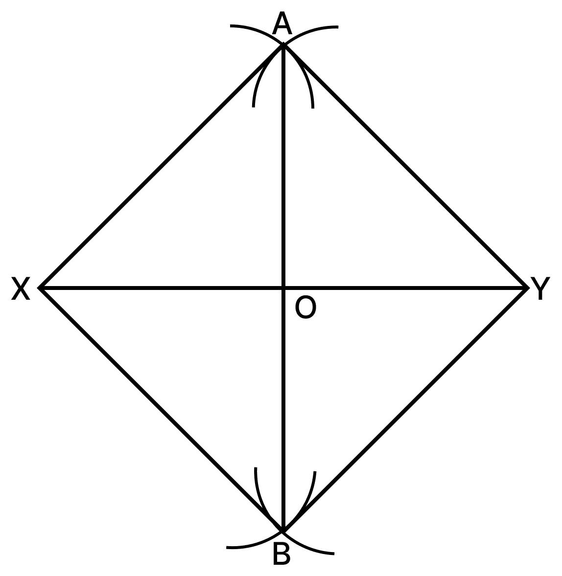
Step 1: △ABX ≅ △ABY
AX = AY (same radius)
BX = BY (same radius)
AB = AB (common side)
⇒ △ABX ≅ △ABY (by SSS congruence condition)
∴ ∠XAB = ∠YAB (corresponding parts of congruent triangles)
Since O lies on AB, this means ∠XAO = ∠YAO.
Step 2: △AOX ≅ △AOY
AX = AY (same radius)
∠XAO = ∠YAO (proved above)
AO = AO (common side)
⇒ △AOX ≅ △AOY (by SAS congruence condition)
∴ OX = OY and ∠AOX = ∠AOY (corresponding parts of congruent triangles)
Step 3: The angle is 90°
∠AOX and ∠AOY together form a straight angle.
∠AOX + ∠AOY = 180°
⇒ ∠AOX + ∠AOX = 180°
⇒ 2∠AOX = 180°
⇒ ∠AOX = ∠AOY = 90°
Thus O is the midpoint of XY and AB is perpendicular to XY. The proof uses only the fact that AX = AY = BX = BY; it does not depend on their actual numerical lengths.
Hence, whenever equal-radius arcs from X and Y intersect above and below XY, the line joining the two points of intersection is the perpendicular bisector of XY.
Justify the following statement using the facts that we have established.
Any point that has the same distance from X and Y lies on the perpendicular bisector of XY.
Answer
Let P be any point such that PX = PY.
Let O be the midpoint of XY, so that OX = OY. Join PO, PX and PY.
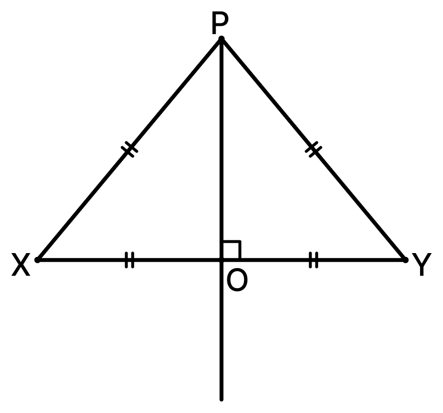
In △POX and △POY,
PX = PY (given)
OX = OY (O is the midpoint of XY)
PO = PO (common side)
⇒ △POX ≅ △POY (by SSS congruence condition)
∴ ∠POX = ∠POY (corresponding parts of congruent triangles)
Since ∠POX and ∠POY together form a straight angle,
∠POX + ∠POY = 180°
⇒ 2∠POX = 180°
⇒ ∠POX = ∠POY = 90°
So the line PO passes through the midpoint O of XY and is perpendicular to XY. That is, PO is the perpendicular bisector of XY. Since XY has only one perpendicular bisector, PO is that line, and the point P lies on it.
Hence, any point that is at the same distance from X and Y lies on the perpendicular bisector of XY.
When constructing the perpendicular bisector, is it necessary to have the same radius for the arcs above and below XY? Explore this through construction, and then justify your answer.
[Hint 1: Any point that is of the same distance from X and Y lies on the perpendicular bisector.
Hint 2: We can draw the whole line if any two of its points are known.]
Answer
No, it is not necessary. The arcs above XY and the arcs below XY may be drawn with two different radii.
Steps of construction:
- Draw a line segment XY.
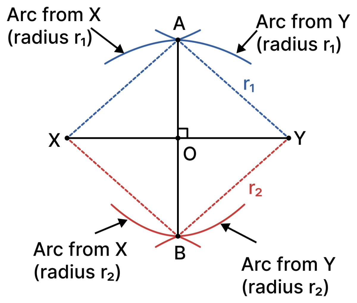
- Taking a radius r1 (greater than half of XY), draw arcs from X and then from Y above XY. Mark the point where they meet as A.
- Now take a different radius r2 (also greater than half of XY). Draw arcs from X and then from Y below XY. Mark the point where they meet as B.
- Join A and B.
Justification:
The arcs that meet at A were drawn with the same radius r1 from X and from Y.
⇒ AX = AY = r1, so A is at the same distance from X and Y.
The arcs that meet at B were drawn with the same radius r2 from X and from Y.
⇒ BX = BY = r2, so B is also at the same distance from X and Y.
Any point that is at the same distance from X and Y lies on the perpendicular bisector of XY (Hint 1). So both A and B lie on the perpendicular bisector, and two points are enough to draw the whole line (Hint 2).
Note that r1 and r2 do not appear anywhere in this reasoning — only that each pair of arcs was drawn with equal radii. Also, each radius must be more than half of XY, otherwise the two arcs of that pair will not meet.
Hence, the radii of the arcs above and below XY need not be the same; AB is the perpendicular bisector of XY in either case.
Is it necessary to construct the pairs of arcs above and below XY? Instead, can we construct both the pairs of arcs on the same side of XY? Explore this through construction, and then justify your answer.
Answer
No, it is not necessary. Both pairs of arcs can be drawn on the same side of XY, provided the two pairs are drawn with different radii.
Steps of construction:
- Draw a line segment XY.
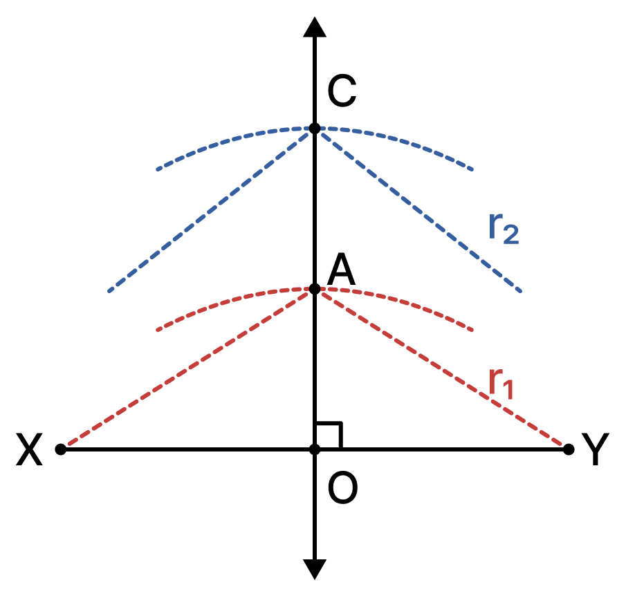
- Taking a radius r1 (greater than half of XY), draw arcs from X and then from Y above XY. Mark the point where they meet as A.
- Taking a different radius r2 (r2 ≠ r1, and greater than half of XY), again draw arcs from X and then from Y above XY. Mark the point where they meet as C.
- Join A and C, and extend this line on both sides.
Justification:
AX = AY = r1 and CX = CY = r2.
⇒ Both A and C are at the same distance from X and Y.
∴ Both A and C lie on the perpendicular bisector of XY, and the line drawn through them is the perpendicular bisector.
The two radii must be different. If r2 = r1, the second pair of arcs meets at the same point A. We would then have only one point of the perpendicular bisector, and a single point is not enough to fix a line.
Hence, both pairs of arcs may be drawn on the same side of XY, as long as the two pairs use different radii.
While constructing one pair of intersecting arcs, is it necessary that we use the same radii for both of them? Explore this through construction, and then justify your answer.
Answer
Yes. If the point of intersection is to lie on the perpendicular bisector of XY, the two arcs in that pair must be drawn with the same radius.
Steps of construction:
- Draw a line segment XY.
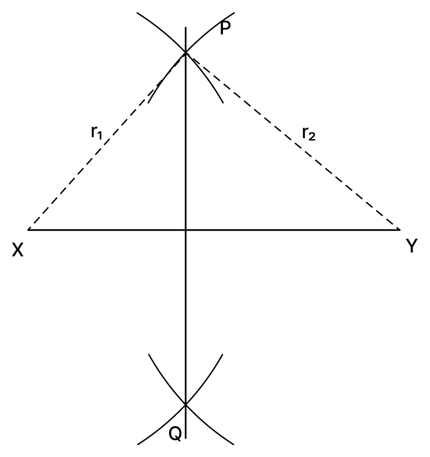
- With X as centre and radius r1, draw an arc.
- With Y as centre and a different radius r2, where r1 ≠ r2, draw an arc cutting the first arc at P.
- Repeat the construction on the other side of XY to get the second point of intersection Q, and join PQ.
Justification:
Since P lies on the arc drawn with centre X,
PX = r1.
Since P also lies on the arc drawn with centre Y,
PY = r2.
But r1 ≠ r2.
⇒ PX ≠ PY.
Therefore, P is not at the same distance from X and Y and hence does not lie on the perpendicular bisector of XY. The same is true for Q.
In the construction, PQ may still be perpendicular to XY, but it does not generally pass through the midpoint of XY. Therefore, PQ is not the perpendicular bisector of XY.
Hence, the two arcs in a pair must be drawn with the same radius if their point of intersection is to lie on the perpendicular bisector of XY.
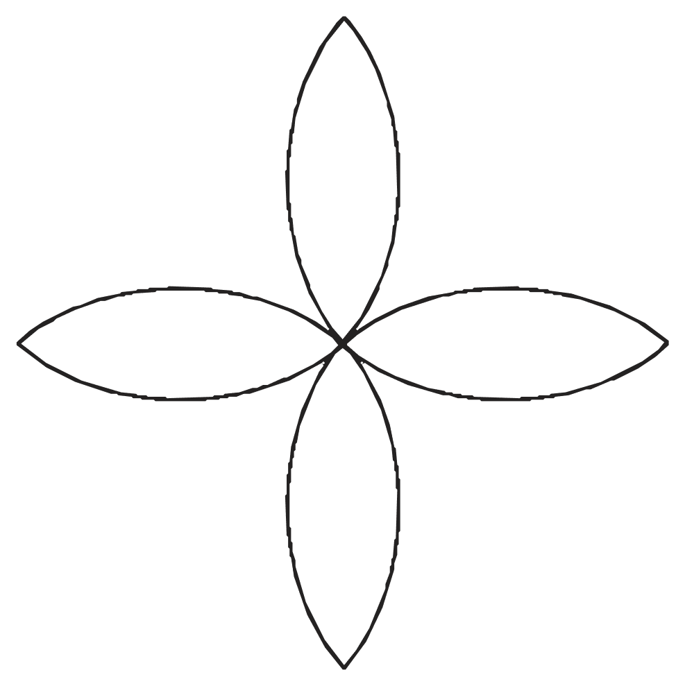
Recreate this design using only a ruler and compass —
Answer
The design has four identical petals placed around a common centre, two along a horizontal line and two along a vertical line. So the supporting lines are a pair of perpendicular lines through the centre, and each petal is an 'eye' constructed on one of the four equal arms.
Steps of construction:
- Draw a line and mark a point O on it.
- Construct a perpendicular to the line at O using the compass.
- With O as centre and any convenient radius r, draw a circle.
- Let the circle cut the horizontal line at P and Q, and the vertical line at R and S.
Thus, OP = OQ = OR = OS = r. - To construct the petal on OP:
- With O as centre and radius OP, draw an arc above the segment OP.
- With P as centre and the same radius OP, draw another arc cutting the first arc at A.
- Keeping the same radius, draw another pair of arcs below OP meeting at B.
- With A as centre and radius AO, draw the arc joining O and P.
- With B as centre and radius BO, draw the second arc joining O and P.
These two arcs form one petal.
- Repeat Step 5 on the remaining three arms OQ, OR, and OS, using the same radius each time.
- Darken the eight arcs forming the four petals and erase the construction lines.
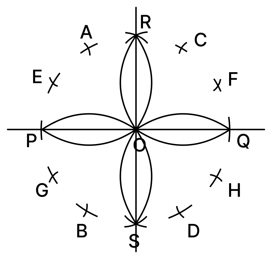
Hence, the design is obtained by constructing two perpendicular lines through O and drawing an 'eye' on each of the four equal arms OP, OQ, OR and OS.
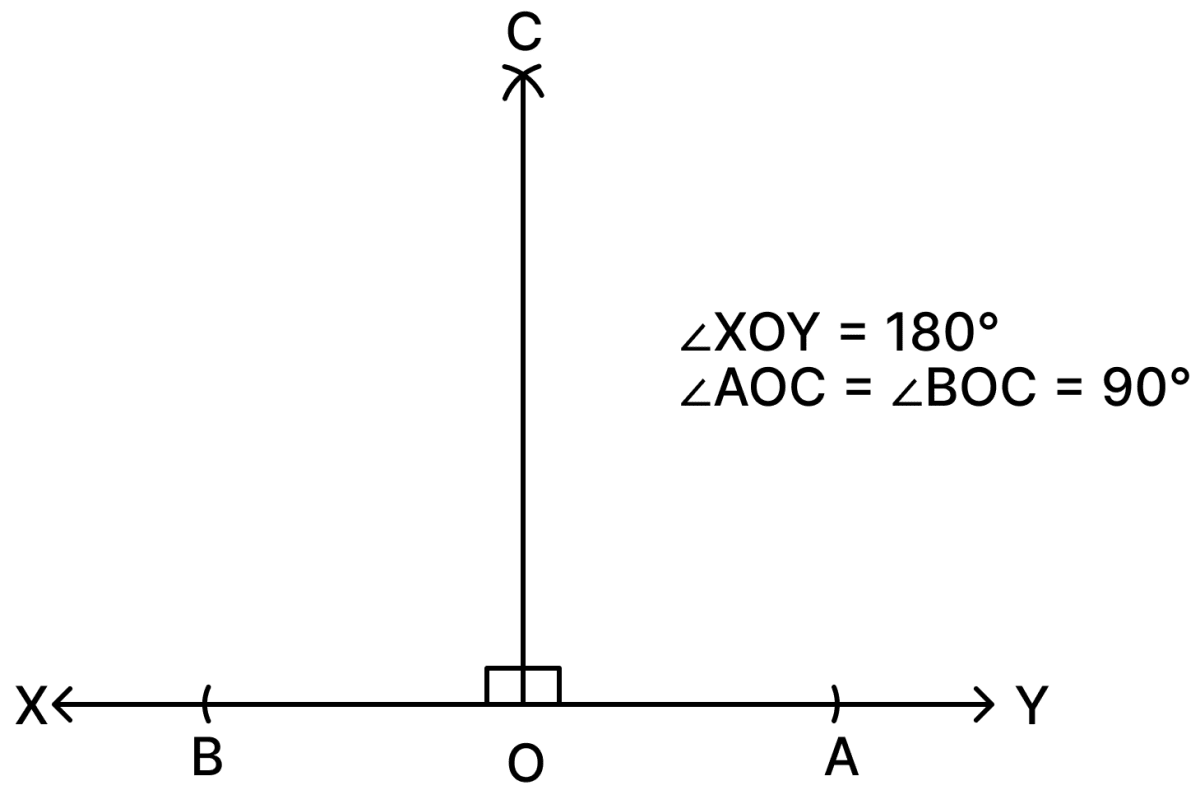
Can we extend the method of constructing the perpendicular bisector to construct a 90° angle at any point on a line?
Answer
Yes. If we can find a segment of the line whose midpoint is O, then the perpendicular bisector of that segment will pass through O and will be perpendicular to the line. That gives us a 90° angle at O.
Steps of construction:
- Draw a line and mark a point O on it.
- With O as centre and any convenient radius, draw arcs cutting the line at X and Y, one on each side of O. Then OX = OY, so O is the midpoint of XY.
- With X as centre and a radius more than half of XY, draw an arc above the line.
- With Y as centre and the same radius, draw another arc cutting the previous arc at A.
- Join OA.
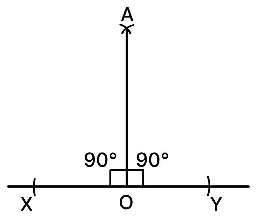
Here we need only one pair of intersecting arcs, because O is already a second point lying on the perpendicular bisector of XY.
The line AO is the perpendicular bisector of XY, so it is perpendicular to XY at O.
∴ ∠AOX = ∠AOY = 90°
Hence, the perpendicular bisector construction can be extended to construct a 90° angle at any given point O on a line.
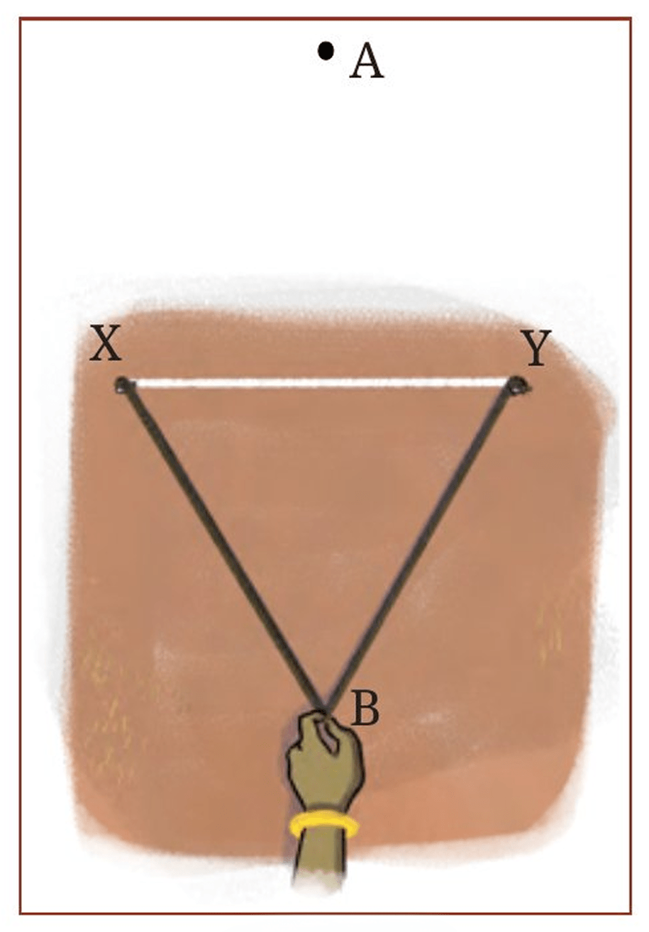
Justify why AB in Fig. 6.4 is the perpendicular bisector.
Answer
In this construction, the rope was folded into half and its midpoint was marked before the ends were fastened to the poles at X and Y.
So the rope is divided into two parts of equal length by its midpoint.
When the midpoint is pulled above XY until both parts are fully stretched, the two stretched parts become the straight segments AX and AY, each equal to half the length of the rope.
⇒ AX = AY
Similarly, when the midpoint is pulled below XY, we get
⇒ BX = BY
Thus, A and B are both at the same distance from X and Y.
We have already established that any point which is at the same distance from X and Y lies on the perpendicular bisector of XY.
⇒ A and B both lie on the perpendicular bisector of XY.
Since a line is fixed by two of its points, the line AB must be the perpendicular bisector itself.
This can also be seen through congruence. Let O be the point where AB meets XY.
In △ABX and △ABY:
AX = AY (halves of the same rope)
BX = BY (halves of the same rope)
AB = AB (common side)
∴ △ABX ≅ △ABY (SSS congruence)
⇒ ∠XAO = ∠YAO (corresponding parts of congruent triangles)
Now, in △AOX and △AOY:
AX = AY
∠XAO = ∠YAO (proved above)
AO = AO (common side)
∴ △AOX ≅ △AOY (SAS congruence)
⇒ OX = OY, so O is the midpoint of XY, and ∠AOX = ∠AOY.
Since ∠AOX and ∠AOY together form a straight angle,
∠AOX + ∠AOY = 180°
⇒ ∠AOX = ∠AOY = 90°
Hence, AB bisects XY and is perpendicular to it, that is, AB is the perpendicular bisector of XY.
Can you think of different methods to construct a 90° angle at a given point on a line using a rope?
Answer
Let the line be drawn on the ground and let O be the given point on it. Here are three methods.
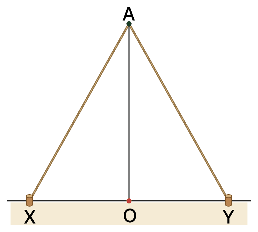
Method 1 — Using the perpendicular bisector of a segment with midpoint O
- Take a short rope, hold one end at O and mark points X and Y on the line on either side of O, using the same length of rope. Then OX = OY, so O is the midpoint of XY.
- Fix pegs at X and Y.
- Take a longer rope, make loops at its ends, fold it in half and mark its midpoint. Fasten the loops to the pegs at X and Y.
- Pull the midpoint of the rope to one side of the line until both parts are fully stretched, and mark this position as A.
- Join O and A.
Since AX = AY and OX = OY, both A and O lie on the perpendicular bisector of XY, so OA is perpendicular to the line at O.
∴ ∠AOX = 90°
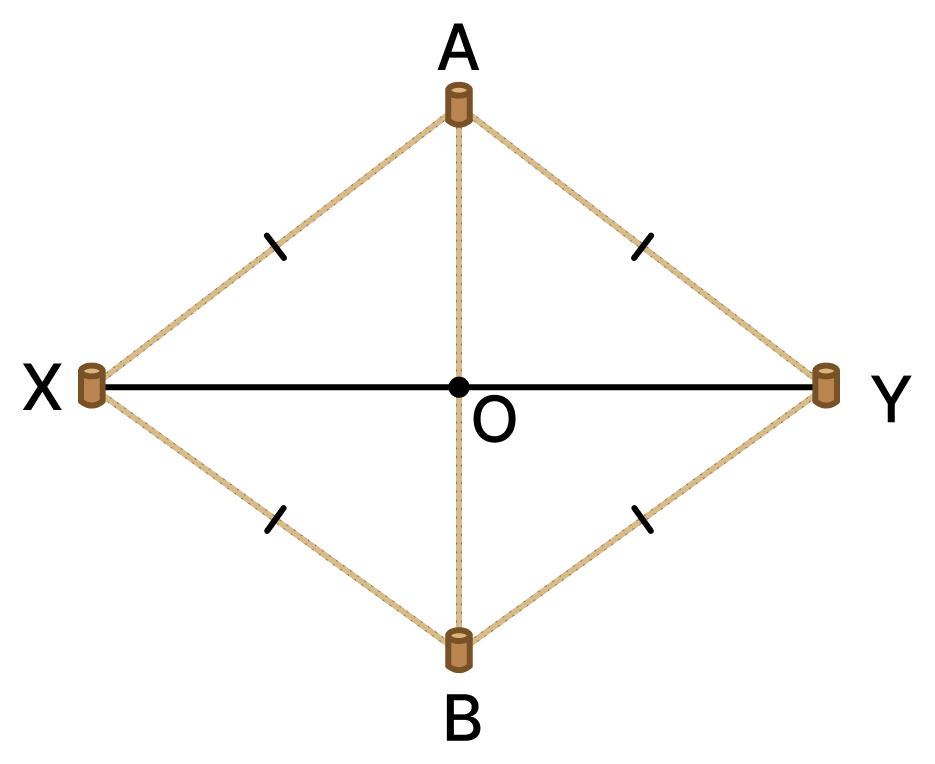
Method 2 — Using a rhombus made with the rope
- Fix pegs at X and Y on the line such that OX = OY.
- Take a rope and mark a convenient length on it (longer than half of XY). Using this same length each time, locate a point A above the line with XA = YA, and a point B below the line with XB = YB. Peg the rope at each stage so that it is fully stretched.
- Then XA = AY = YB = BX, so XAYB is a rhombus. Join A and B; this diagonal passes through O and is perpendicular to XY.
Method 3 — Using a knotted rope (the Śulba-Sūtra style rope)
- Take a rope and tie knots on it at equal distances so that the rope is divided into 12 equal parts. Join its two ends to form a closed loop.
- Peg the loop at O, and at a point P on the line such that OP is 3 parts long.
- Stretch the remaining rope away from the line and peg the knot that leaves 4 parts on the side OQ and 5 parts on the side PQ. Mark this third corner as Q.
- The rope now forms a triangle OPQ with sides 3, 4 and 5 parts, and the angle at O — between OP along the line and OQ — is a right angle.
This works because a triangle with sides in the ratio 3 : 4 : 5 is always right-angled at the vertex where the sides of 3 and 4 units meet.
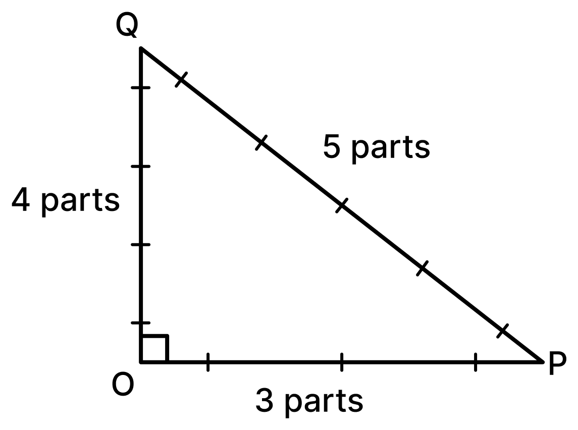
Hence, a angle can be constructed at a point on a line using a rope in several ways — by the perpendicular bisector method, by the rhombus method, or by a knotted 3 : 4 : 5 rope.
How do we construct this figure?
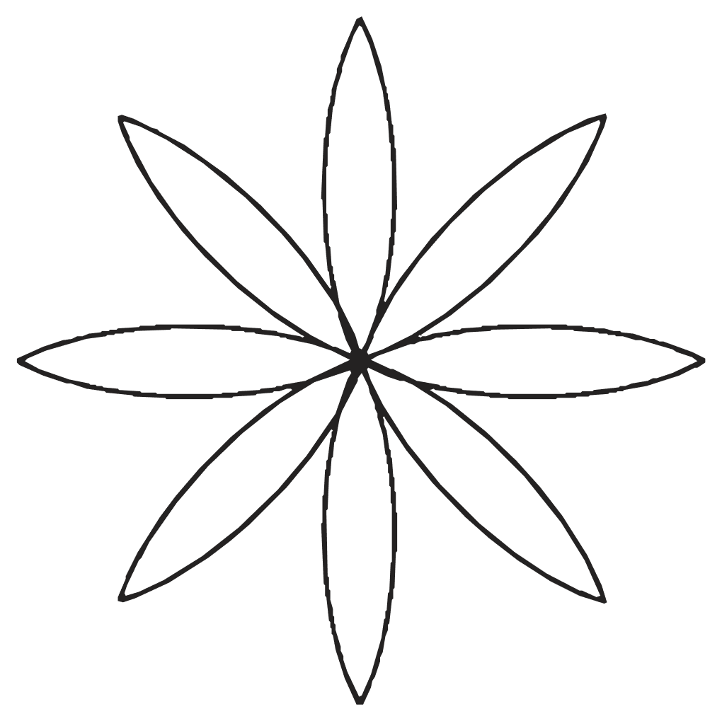
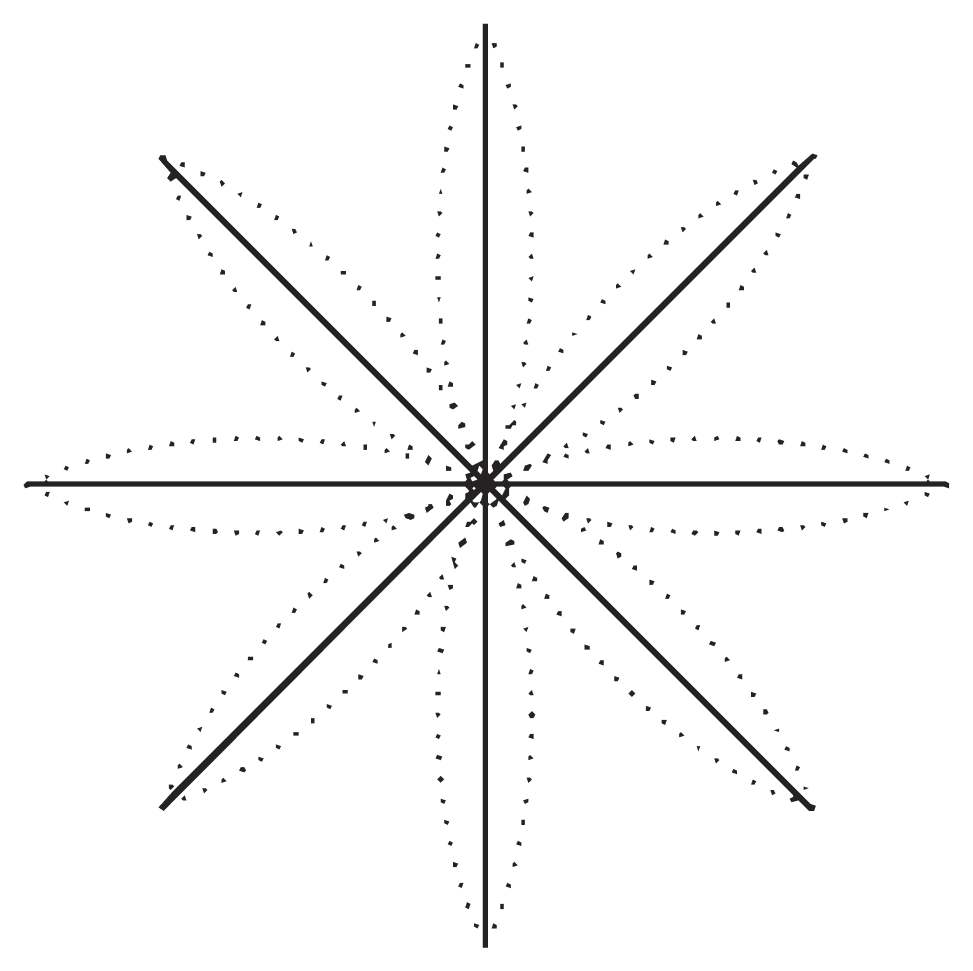
The supporting lines for this figure will look like this.
Answer
The figure has 8 identical petals arranged around a common centre. So the supporting lines are 8 rays drawn from the centre, with equal angles between adjacent rays, and each petal is an 'eye' constructed on one ray.
Since 360° has to be divided equally into 8 parts, the angle between two adjacent rays must be . A 45° angle is obtained by bisecting a 90° angle.
Steps of construction:
- Draw a line and mark a point O on it.
- Construct a perpendicular to this line at O and extend it on both sides. We now have 4 rays from O, with an angle of 90° between adjacent rays.
- Bisect each of these four right angles. To bisect ∠POY: with O as centre, mark points A and B on the two arms with OA = OB; then, with A and B as centres and the same radius, draw arcs meeting at C; the ray OC bisects ∠POY. Repeat this on all other arms.
- We now have 8 rays from O, with an angle of 45° between every pair of adjacent rays.
- With O as centre and a radius r, draw arcs cutting the eight rays at eight points. These are the tips of the petals, and all of them are at the same distance r from O.
- To draw the petal along a ray OP: with O as centre and any radius more than OP, draw arcs on both sides of OP; with P as centre and the same radius, cut them at M and N. With M as centre and radius MO, draw an arc from O to P; with N as centre and radius NO, draw the second arc from O to P. The two arcs form one petal.
- Repeat Step 6 on each of the eight rays, using the same radius every time, so that all the petals are identical.
- Darken the petals and rub out the supporting lines and arcs.
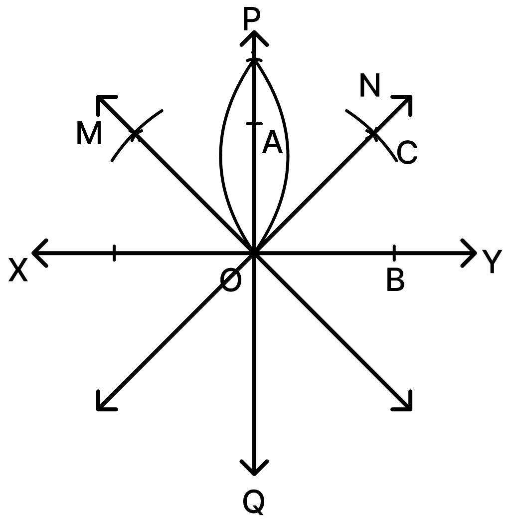
Hence, the 8-petalled figure is constructed by drawing 8 rays from a point, 45° apart, and constructing an identical 'eye' on each ray.
How do we construct a 45° angle using only a ruler and a compass?
Answer
We already know how to construct a 90° angle. If this right angle is divided into two equal parts, that is, if it is bisected, each part is 45°.
Steps of construction:
- Draw a line and mark a point O on it.
- With O as centre and any convenient radius, draw arcs cutting the line at X and Y. Then O is the midpoint of XY.
- With X as centre and a radius more than half of XY, draw an arc above the line.
- With Y as centre and the same radius, draw another arc cutting the previous arc at A. Join OA.
Since OA is the perpendicular bisector of XY, ∠AOY = 90°.
- With O as centre and any convenient radius, draw an arc cutting OY at P and OA at Q.
- With P as centre and a radius more than half of PQ, draw an arc inside ∠AOY.
- With Q as centre and the same radius, draw another arc cutting the previous arc at B. Join OB.
OR bisects ∠AOY, so ∠BOY = = 45°.
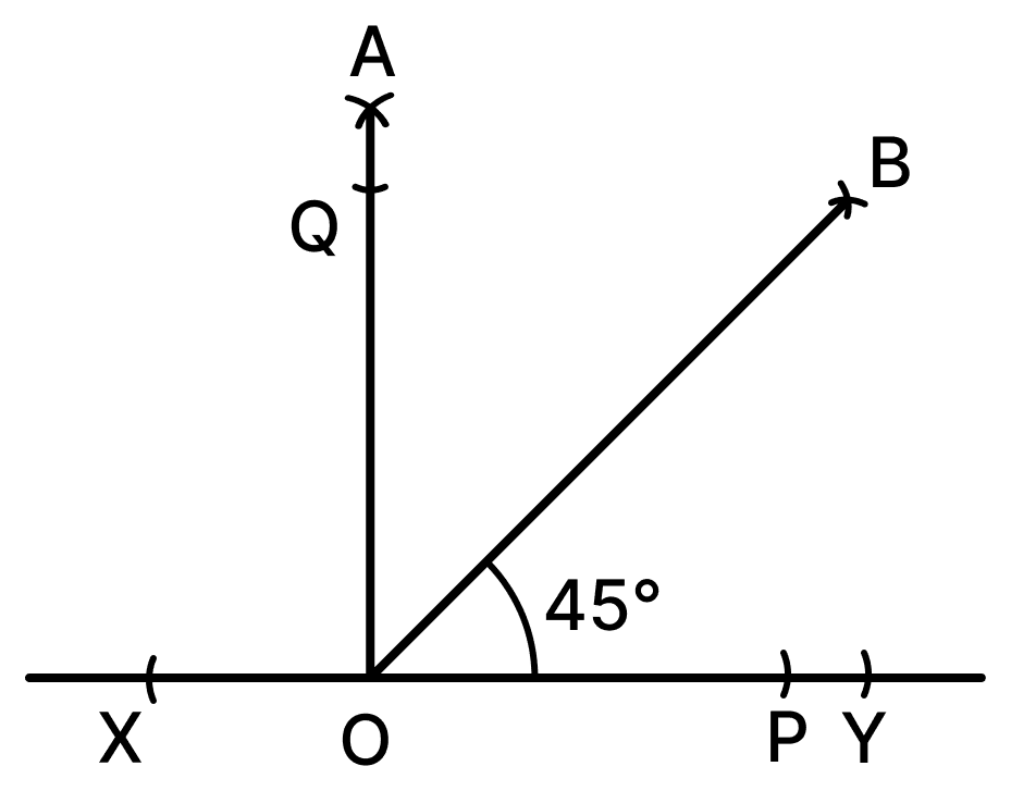
Hence, a 45° angle is constructed by first constructing a 90° angle and then bisecting it.
Construct at least 4 different angles. Draw their bisectors.
Answer
Draw four angles of different sizes — for example an acute angle, a right angle, an obtuse angle and a straight angle — and bisect each of them by the same steps.
Steps of construction (for any angle ∠XOY):
- Draw the angle ∠XOY.
- With O as centre and any convenient radius, draw an arc cutting OY at A and OX at B.
- With A as centre and a radius more than half of AB, draw an arc in the interior of the angle.
- With B as centre and the same radius, draw another arc cutting the previous arc at C.
- Join OC.
OC is the required bisector, because OA = OB, AC = BC and OC is common, so △OAC ≅ △OBC by the SSS congruence condition, giving ∠AOC = ∠BOC.
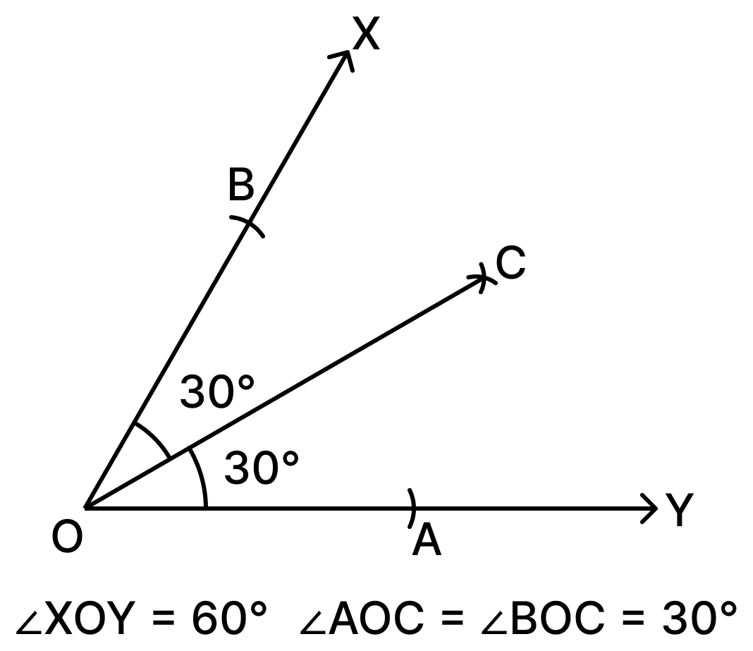
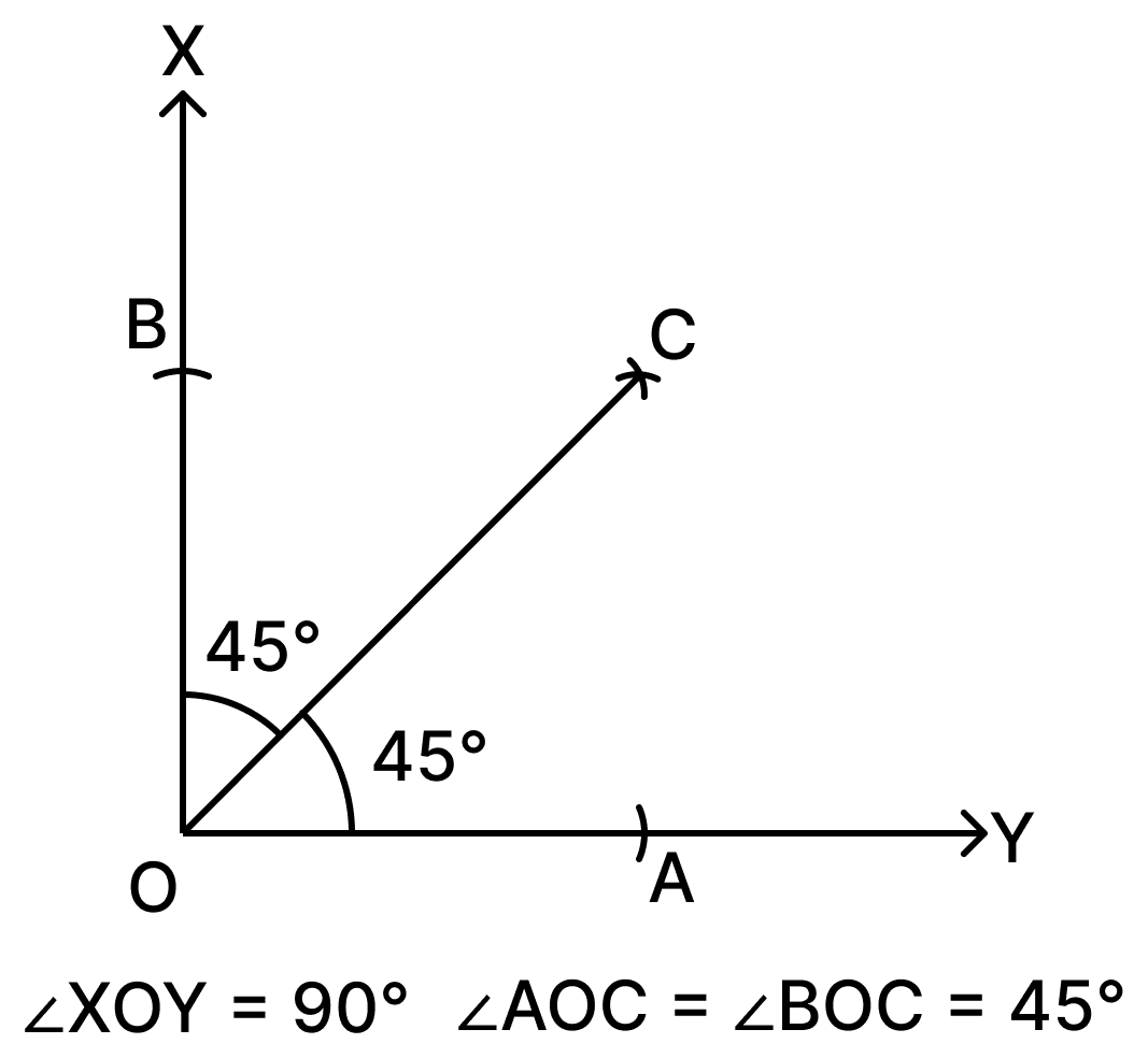
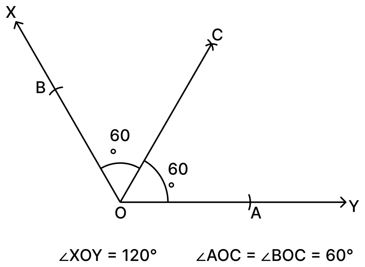
Hence, each of the four angles is divided into two equal parts by the bisector drawn.
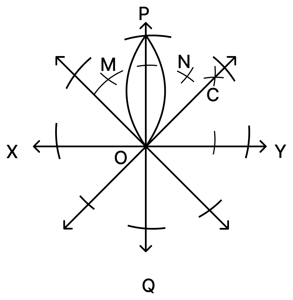
Construct the 8-petalled figure shown in Fig. 6.5.
Answer
The figure has 8 petals arranged around a centre, so the supporting lines are 4 lines through the centre with an angle of = 45° between adjacent lines.
Steps of construction:
- Draw a line and mark a point O on it.
- Construct a perpendicular to this line at O and extend it on both sides. We now have 4 rays from O, with an angle of 90° between adjacent rays.
- Bisect each of these four right angles. To bisect ∠POY: with O as centre, mark points A and B on the two arms with OA = OB; then, with A and B as centres and the same radius, draw arcs meeting at C; the ray OC bisects ∠POY. Repeat this on all other arms.
- We now have 8 rays from O, with an angle of 45° between every pair of adjacent rays.
- With O as centre and a radius r, draw arcs cutting the eight rays at eight points. These are the tips of the petals, and all of them are at the same distance r from O.
- To draw the petal along a ray OP: with O as centre and any radius more than OP, draw arcs on both sides of OP; with P as centre and the same radius, cut them at M and N. With M as centre and radius MO, draw an arc from O to P; with N as centre and radius NO, draw the second arc from O to P. The two arcs form one petal.
- Repeat Step 6 on each of the eight rays, using the same radius every time, so that all the petals are identical.
- Darken the petals and rub out the supporting lines and arcs.
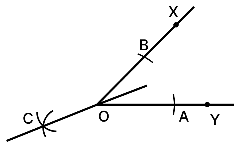
In Step 2 of angle bisection, if arcs of equal radius are drawn on the other side, as shown in the figure, will the line OC still be an angle bisector? Explore this through construction, and then justify your answer.
Answer
Yes, the line OC is still the angle bisector, provided the radius chosen is long enough for the two arcs to meet.
Exploration through construction:
- Draw an angle ∠XOY.
- With O as centre, draw an arc cutting the arms of the angle at A and B.
- Instead of drawing the next pair of equal arcs inside the angle, draw them on the opposite side of AB, as shown in the figure. Let them intersect at C.
- Join O and C, and produce the line through O.
Justification:
The arcs drawn from A and from B have the same radius, so
CA = CB (arcs of equal radius)
⇒ C is at the same distance from A and B, so C lies on the perpendicular bisector of AB.
Also, A and B were marked using arcs of the same radius from O, so
OA = OB (arcs of the same radius)
⇒ O too is at the same distance from A and B, so O lies on the perpendicular bisector of AB.
∴ The line OC is the perpendicular bisector of AB.
The bisector of ∠AOB is also the perpendicular bisector of AB (since △OAC ≅ △OBC gives equal angles at O). As a line segment AB has only one perpendicular bisector, the line OC must be the same line as the bisector of ∠AOB.
The only difference is that the point C now lies on the opposite side of O. So the ray OC lies inside the angle vertically opposite to ∠AOB, and it is the ray obtained by producing OC backwards through O that lies inside ∠AOB.
Hence, the line OC is still the angle bisector of ∠AOB, but it has to be produced beyond O to lie within the angle.
What are the other angles that can be constructed using angle bisection? Can you construct 65.5° angle?
Answer
We can start with angles such as 60° and 90° and repeatedly bisect them.
By repeatedly bisecting 90°:
90°, 45°, 22.5°, 11.25°, 5.625°, …
By repeatedly bisecting 60°:
60°, 30°, 15°, 7.5°, 3.75°, …
We can also combine constructible angles. For example:
75° = 60° + 15°
105° = 90° + 15°
120° = 60° + 60°
135° = 90° + 45°
150° = 90° + 60°
165° = 150° + 15°
Other angles such as 67.5°, 63.75° and 65.625° can also be obtained by combining and bisecting the angles constructed above.
However, 65.5° is not obtained from the 60° and 90° constructions by the repeated angle-bisection methods developed here.
Hence, many angles such as 15°, 22.5°, 30°, 45°, 75°, 105°, 120°, 135° and 150° can be constructed using these methods, but 65.5° cannot be obtained by the angle-bisection constructions used in this chapter.
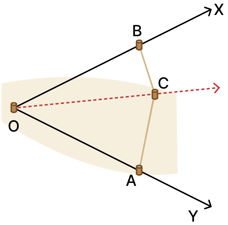
Come up with a method to construct the angle bisector using a rope.
Answer
Let ∠XOY be marked on the ground, with a peg fixed at O.
Steps of construction:
- Take a rope and make a loop at one end. Put this loop around the peg at O and hold a stick at some point of the rope, keeping the rope fully stretched. Mark the point A where the stick touches the arm OY, and the point B where it touches the arm OX. Then OA = OB.
- Fix pegs at A and at B.
- Take another rope, make loops at both its ends, and — leaving out the parts that go into the loops — fold it into half to find and mark its midpoint.
- Fasten the two loops to the pegs at A and B. Pull the midpoint of this rope into the interior of ∠XOY, so that the two parts of the rope on either side are fully stretched. Mark this position of the midpoint as C.
- Stretch a rope from O through C to get the straight line OC.
Justification:
In △OAC and △OBC,
OA = OB (same stretched length of the first rope)
CA = CB (C is the midpoint of the second rope)
OC = OC (common side)
⇒ △OAC ≅ △OBC (by SSS congruence condition)
⇒ ∠AOC = ∠BOC (corresponding parts of congruent triangles)
Hence, OC is the required bisector of ∠XOY, constructed using only a rope.
Construct the following figure.
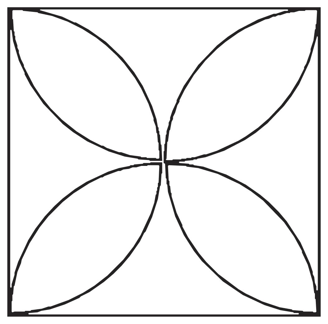
How do we construct the petals so that they are of the maximum possible size within a given square?
Answer
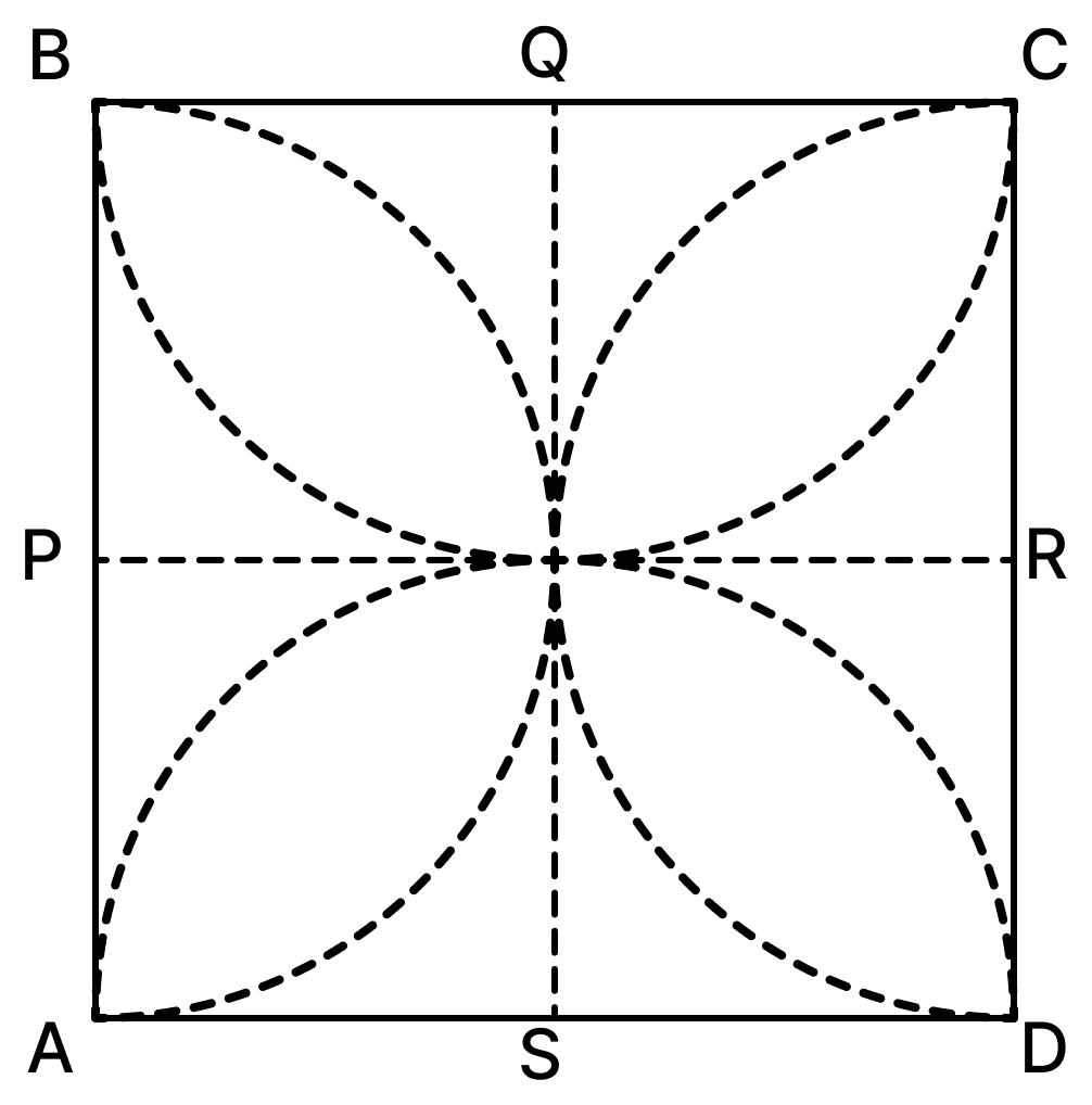
Each petal of the figure has one tip at a corner of the square and the other tip at the centre of the square. Every petal is bounded by two arcs, and each of these arcs is a semicircle drawn inside the square on a side of the square as diameter.
Steps of construction:
- Construct the square ABCD of the given side length.
- Construct the perpendicular bisector of each side and mark the midpoints P, Q, R and S of AB, BC, CD and DA respectively.
- With P as centre and radius PA, draw the semicircle on AB inside the square.
- Similarly, with Q, R and S as centres and radius equal to half the side length, draw semicircles on BC, CD and DA inside the square.
All four semicircles pass through the centre of the square. Two adjacent semicircles meet at a corner of the square and at the centre, and the region between them is one petal.
Why the petals are of the maximum possible size:
Each bounding arc must stay inside the square and its two ends must lie on the square. The largest arc that can be drawn inside the square on one side is the semicircle having that whole side as its diameter, that is, of radius sidelength. Taking a smaller radius would give smaller petals, and taking a larger radius would push the arc outside the square.
Hence, drawing the four semicircles on the four sides of the square as diameters gives four petals of the maximum possible size within the square.
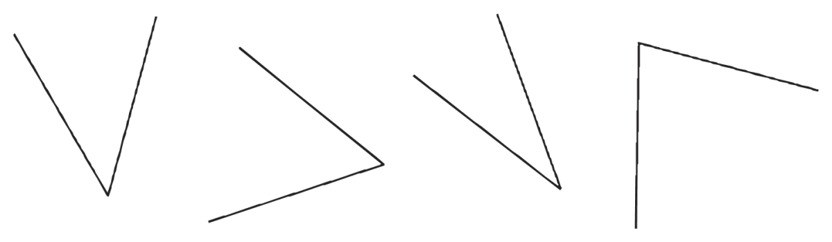
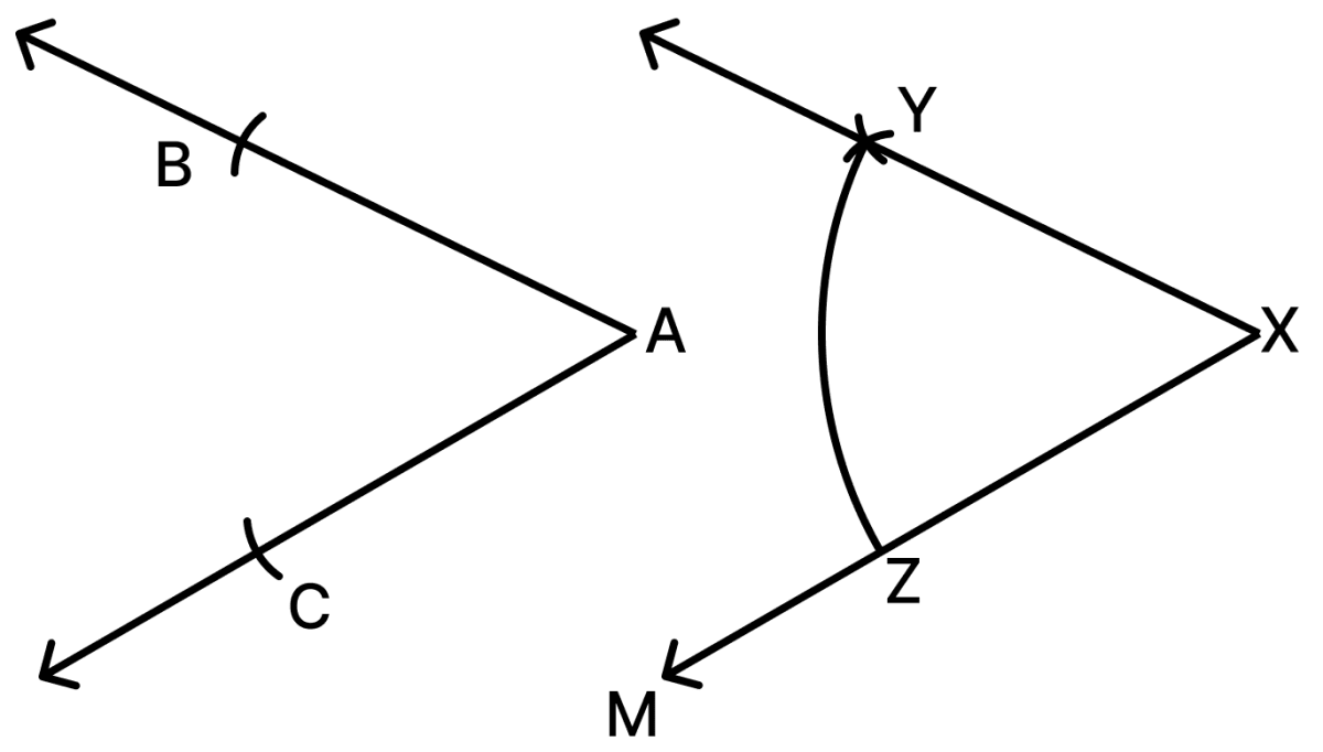
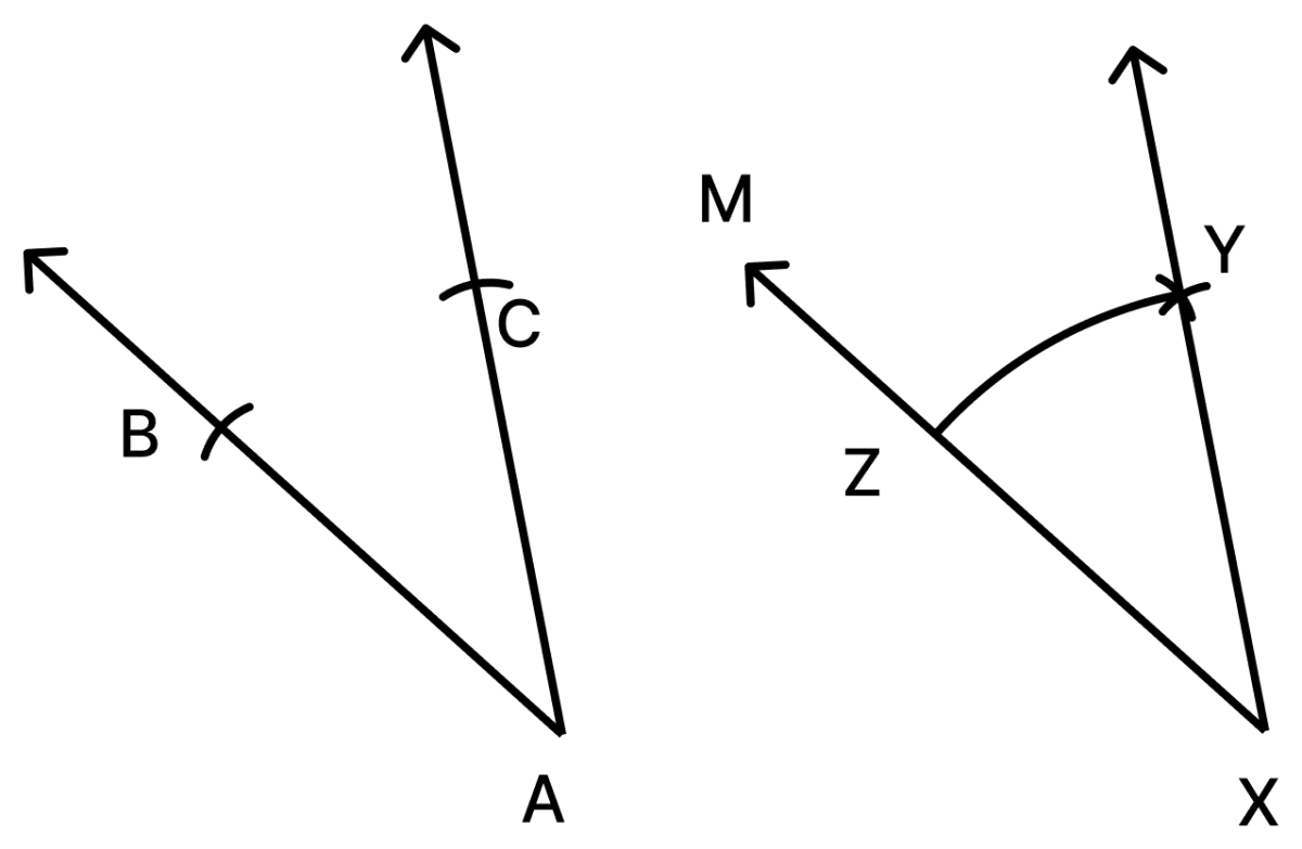
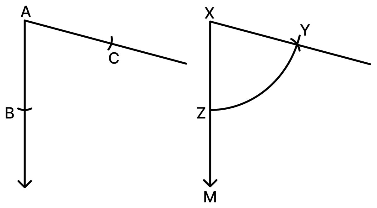
Construct at least 4 different angles in different orientations without taking any measurement. Make a copy of all these angles.
Answer
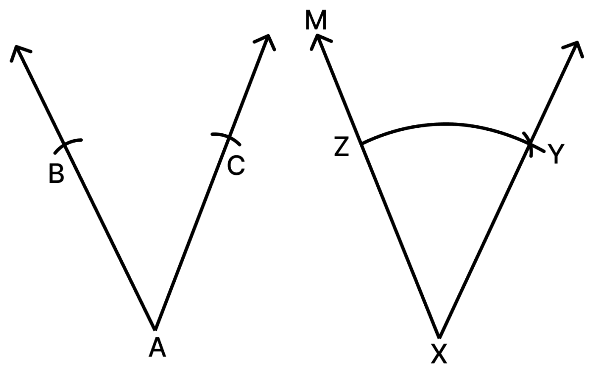
Draw four angles of different sizes, facing in four different directions, without using a protractor or a scale. The same steps are used to copy each one of them. The steps are shown below for one angle ∠A.
Steps of construction:
- Draw an angle ∠A of any size in any orientation.
- Draw a ray XM in the direction in which the copy of the angle is required.
- With A as centre and any convenient radius, draw an arc cutting the two arms of ∠A at B and C. This gives the isosceles triangle △ABC.
- With X as centre and the same radius, draw an arc cutting XM at Z.
- Measure the length BC with the compass. With Z as centre and radius BC, draw an arc cutting the previous arc at Y.
- Join X and Y.
In △ABC and △XYZ,
AB = XZ and AC = XY (arcs of the same radius)
BC = ZY (transferred by the compass)
So, by the SSS congruence condition, △ABC ≅ △XZY.
∴ ∠A = ∠X, that is, ∠X is an exact copy of ∠A.
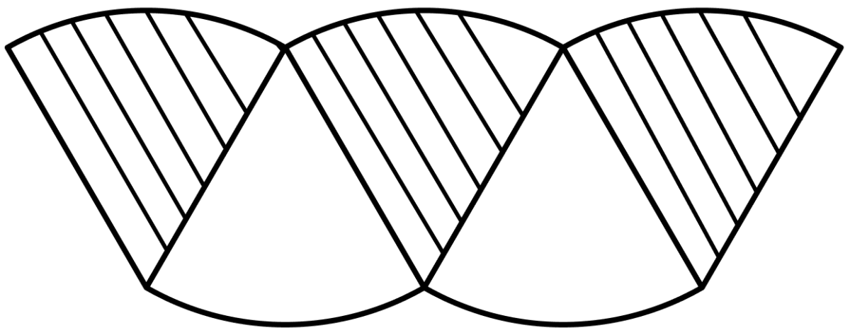
Construct the Fig. 6.6.
Answer
Let the vertices of the required figure be named as A, B, C, D, E, F and G, from left to right.
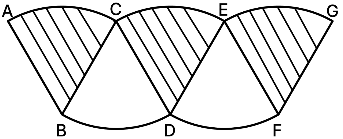
Steps of construction:
- Draw a line segment A′B′ equal in length to AB, in the same direction as AB.
- With B′ as centre and radius A′B′, draw an arc.
- Measure the length AC with the compass. Transfer this length on the arc from A′ to locate C′, so that A′C′ = AC.
- Join B′C′. Shade the sector A′B′C′.
- With C′ as centre and radius B′C′, draw the next arc.
- Measure the length BD with the compass. Transfer this length on the arc from B′ to locate D′, so that B′D′ = BD.
- Join A′C′.
- With D′ as centre and radius C′D′, draw the next arc.
- Measure the length CE with the compass. Transfer this length on the arc from C′ to locate E′, so that C′E′ = CE.
- Join D′E′. Shade the sector C′D′E′.
- With E′ as centre and radius D′E′, draw the next arc.
- Measure the length DF with the compass. Transfer this length on the arc from D′ to locate F′, so that D′F′ = DF.
- Join E′F′.
- With F′ as centre and radius E′F′, draw the last arc.
- Measure the length EG with the compass. Transfer this length on the arc from E′ to locate G′, so that E′G′ = EG.
- Join F′G′. Shade the sector E′F′G′.
- Erase the extra construction arcs and darken the required outline to obtain the required figure.
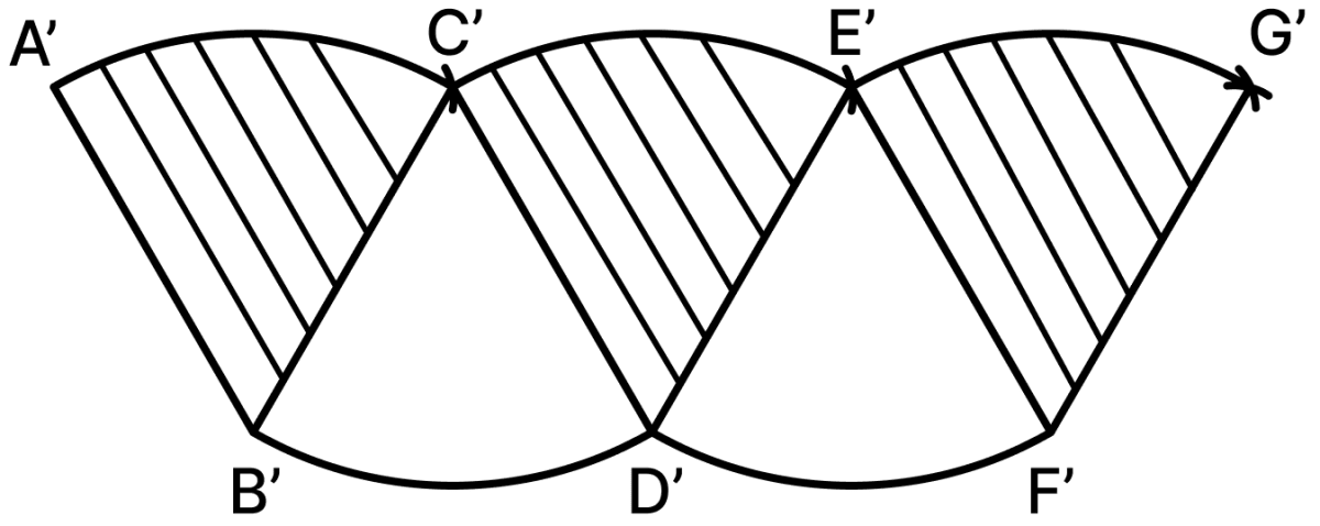
Hence, the required repeating figure is constructed using only a ruler and a compass.
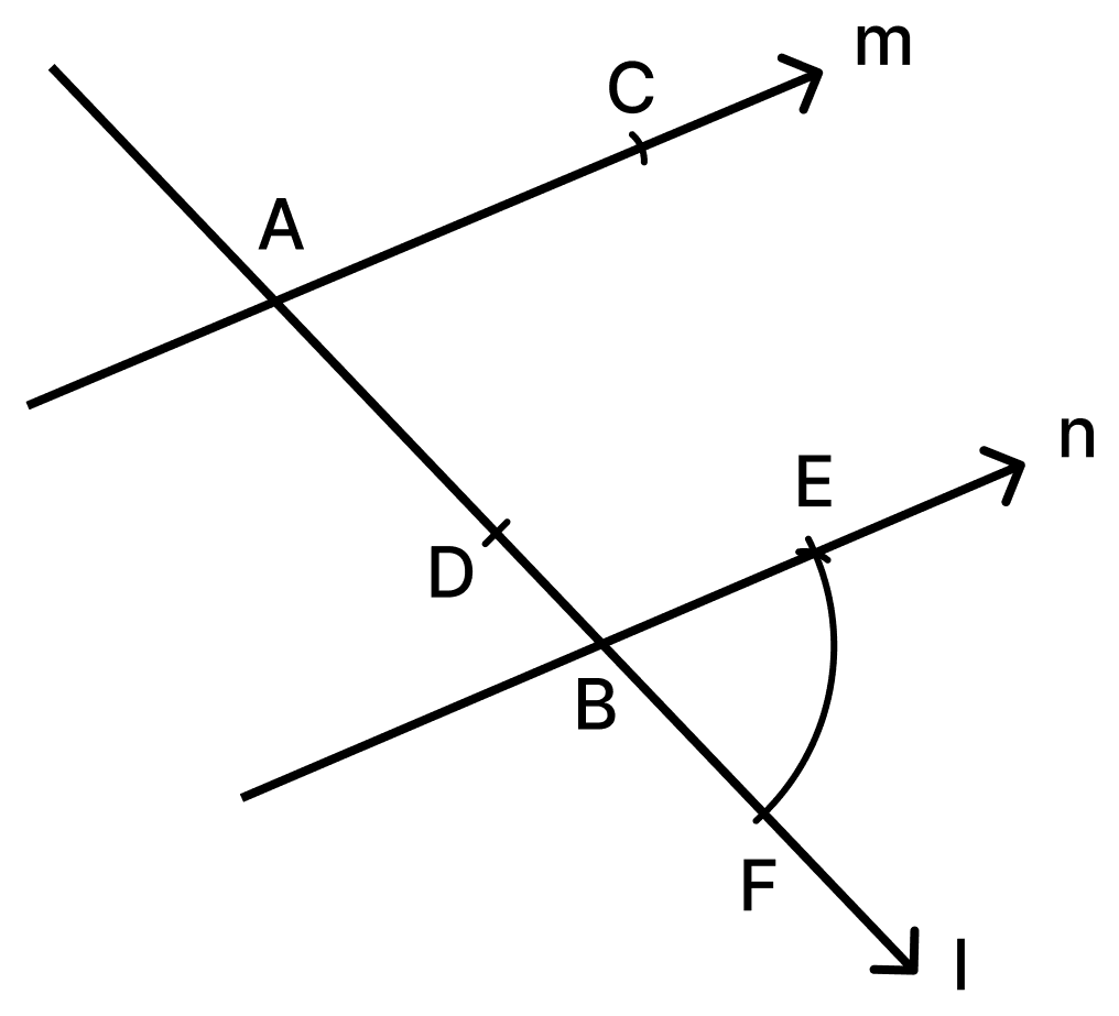
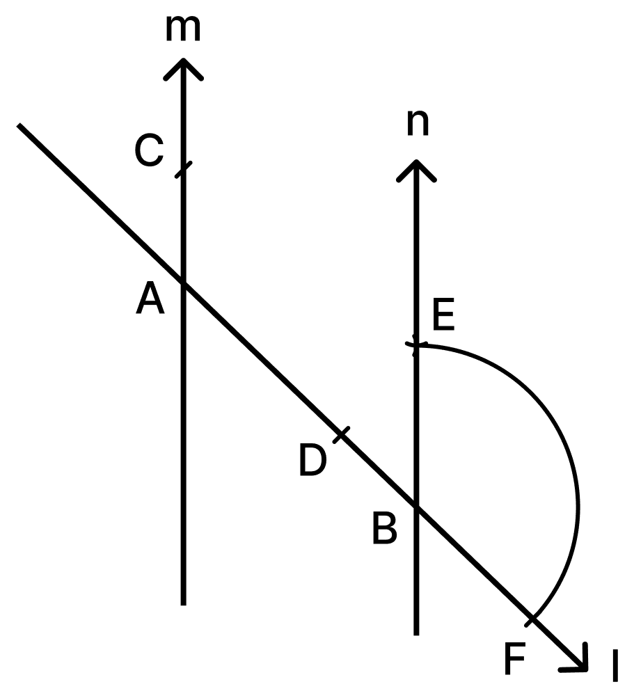
Construct 4 pairs of parallel lines in different orientations.
Answer
Steps of construction:
- Draw the line m in the required orientation.
- Draw any line l cutting m at A, and mark a point B on l.
- With A as centre and any convenient radius, draw an arc cutting m at C and l at D.
- With B as centre and the same radius, draw an arc cutting l at F, taking F on the same side of B as D is of A.
- With F as centre and radius CD, draw an arc cutting the previous arc at E.
- Join B and E and produce it to get the line n.
The corresponding angles ∠DAC and ∠FBE are equal, so m || n.
Repeat these steps for the other three lines, choosing the transversal in a different direction each time.
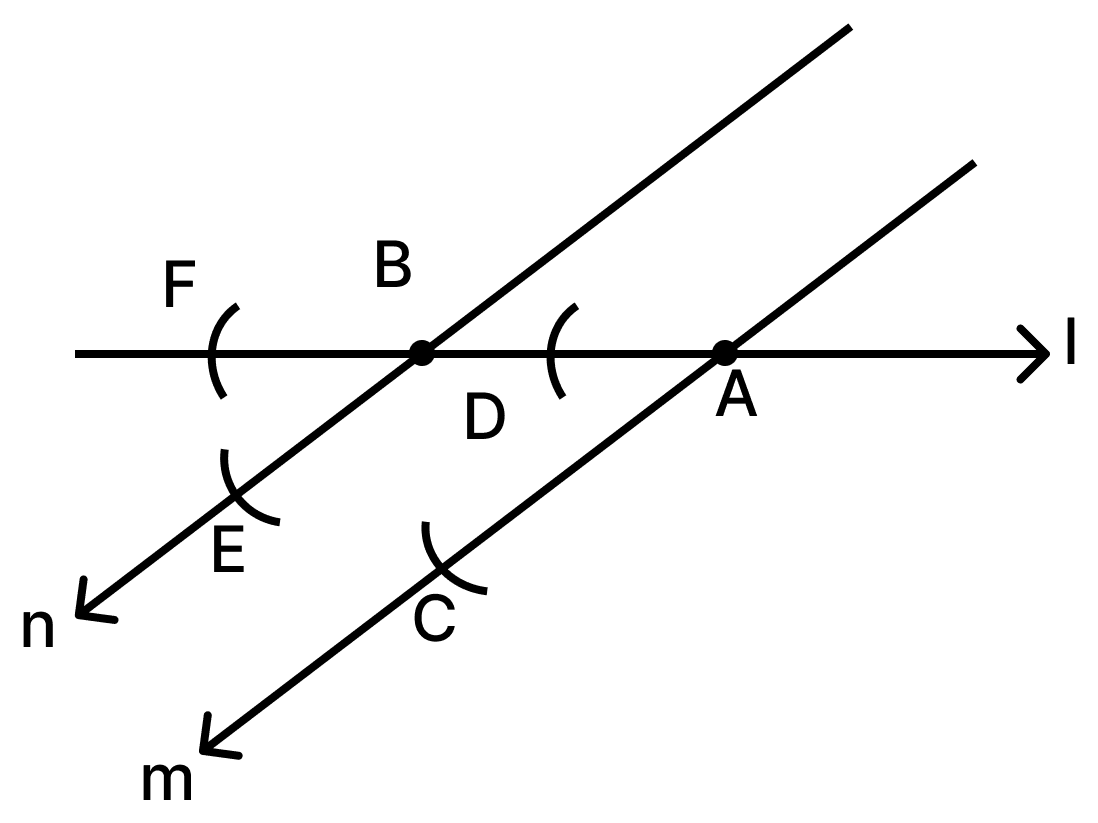
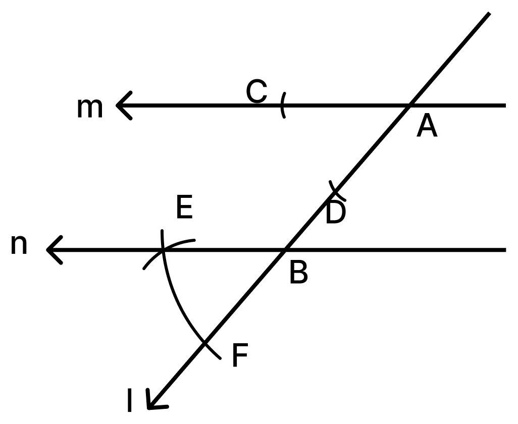
Construct the following figure.
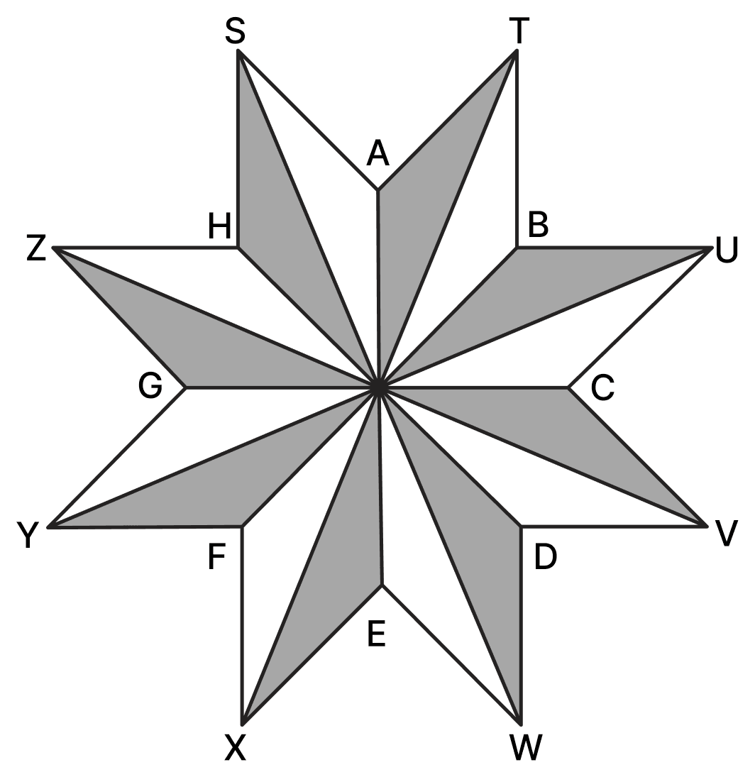
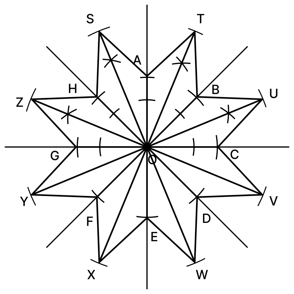
Answer
The figure is an 8-pointed star. Its eight inner points A, B, C, D, E, F, G and H are equally spaced around the centre, and so are its eight outer points S, T, U, V, W, X, Y and Z, each outer point lying exactly midway (in direction) between two inner points.
Angle between two adjacent inner points =
Angle between an inner point and the next outer point =
Steps of construction:
- Draw a line and mark a point O on it. Construct a 90° angle at O. This gives 4 rays through O, at 90° to one another.
- Bisect each of the four right angles. This gives 8 rays through O, at 45° to one another.
- Bisect each of these eight 45° angles. Altogether there are now 16 rays through O, at 22.5° to one another.
- With O as centre and a convenient radius r, cut the first set of 8 rays (the ones at 45° to one another) at A, B, C, D, E, F, G and H.
- With O as centre and a bigger radius R (about twice r), cut the remaining 8 rays at S, T, U, V, W, X, Y and Z.
- Join A–T, T–B, B–U, U–C, C–V, V–D, D–W, W–E, E–X, X–F, F–Y, Y–G, G–Z, Z–H, H–S and S–A. This completes the outline of the star.
- Join O to each of the outer points S, T, U, V, W, X, Y and Z, so that every point of the star is divided into two triangles.
- Erase the extra arcs and lines.
- Shade one triangle of each point, always taking the triangle on the same side, to get the pattern shown.
How do we construct this shape? What supporting lines will you use to draw this arch?
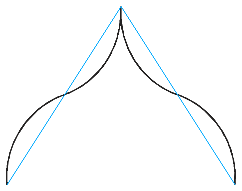
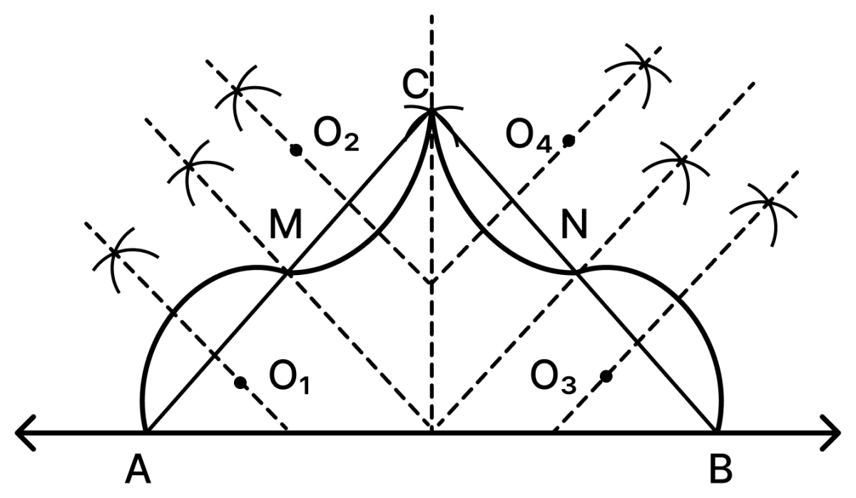
Answer
Steps of construction:
- Draw the base line and mark the points A and B on it, AB being the width of the arch.
- Construct the perpendicular bisector of AB and mark the apex C on it, at the required height.
- Join CA and CB. Since C lies on the perpendicular bisector of AB, CA = CB. These are the supporting lines.
- Construct the perpendicular bisectors of CA and CB, and let them meet CA and CB at their midpoints M and N respectively.
- Draw the perpendicular bisector of AM. Take a convenient point O1 on it, on the inner side of AM. With O1 as centre and radius O1A, draw the arc from A to M. This arc bulges outwards.
- Draw the perpendicular bisector of MC. Take a point O2 on it, on the outer side of MC. With O2 as centre and radius O2M, draw the arc from M to C. This arc bends the other way, so the outline turns at M.
- Repeat steps 5 and 6 on the right half, using the same radii (transferred with the compass) to get the arcs from B to N and from N to C.
- Erase the supporting lines.
If O1, M and O2 are chosen on one straight line through M, the two arcs of a half join smoothly at M.
If their midpoints are marked, will you be able to construct a pointed arch?
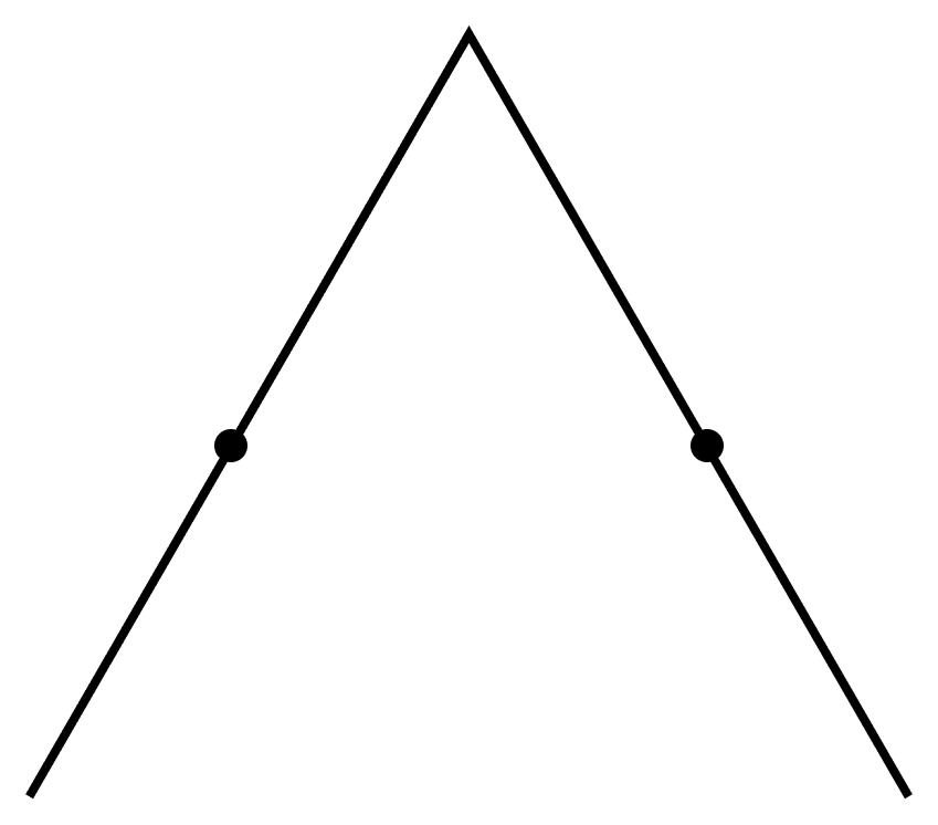
Answer
Yes.
The midpoint of each supporting segment is exactly the point at which one arc ends and the next begins, that is, the point at which the curve changes its direction of bending.
So, once A, M and C are known on the left supporting segment, the two chords AM and MC of the required arcs are known. The centre of a circle passing through two given points is at the same distance from both of them, and hence lies on the perpendicular bisector of the segment joining them. Therefore:
- a centre chosen on the perpendicular bisector of AM gives an arc through A and M, and
- a centre chosen on the perpendicular bisector of MC, on the other side, gives an arc through M and C bending the opposite way.
Taking the two centres on opposite sides is what produces the inflexion at M. Repeating this on the right half with the same radii gives the symmetrical pointed arch.
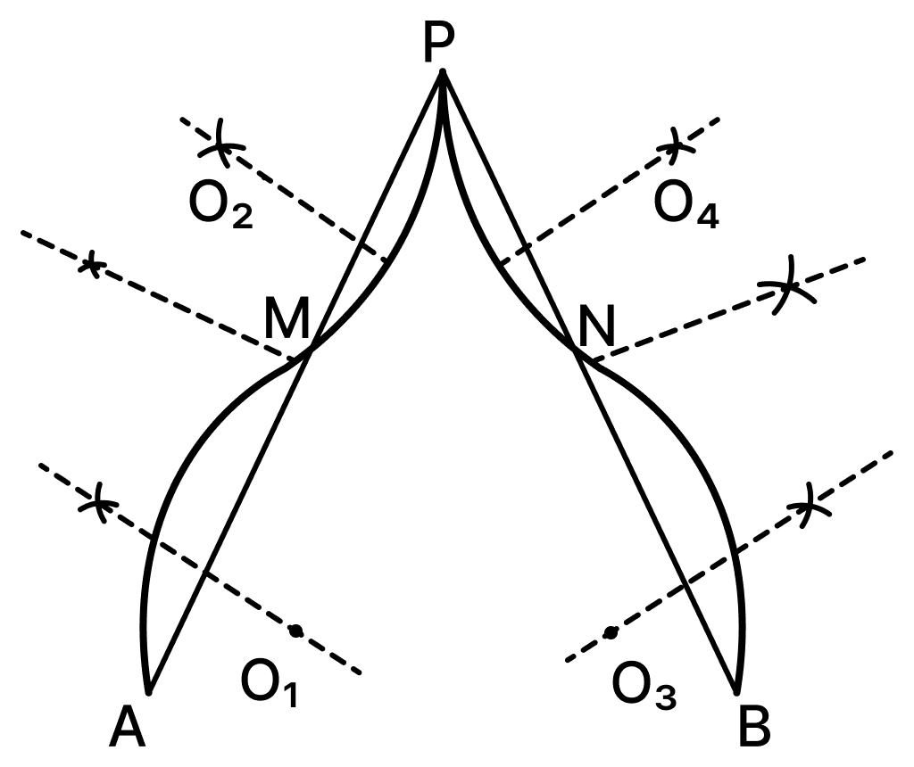
Use support lines in Fig. 6.11 to construct a pointed arch. Make different arches, by changing the radius of the arcs.
Answer
Steps of construction:
- Draw two line segments PA and PB of equal length, meeting at the apex P, as shown in Fig. 6.11.
- Construct the perpendicular bisector of PA and mark its midpoint M. Similarly, construct the perpendicular bisector of PB and mark its midpoint N.
- Take a point O1 on the perpendicular bisector of AM, on the inner side of the support line. With O1 as centre and radius O1A, draw the arc from A to M. This arc bulges outward.
- Take a point O2 on the perpendicular bisector of MP, on the outer side of the support line. With O2 as centre and radius O2M, draw the arc from M to P. This arc bulges inward and meets the apex P.
- Repeat Steps 3 and 4 on the support line PB, taking the centres on the opposite sides so that the two halves are mirror images of each other.
- The two curves meet at P and form the pointed arch.
Since the centres O1 and O2 may be chosen anywhere on the respective perpendicular bisectors, different choices give arcs of different radii. Choosing centres far from AM makes the arc flatter, and choosing centres nearer to AM makes the arc more curved. Repeating the construction with different radii gives arches of different shapes.
How do we construct a regular pentagon (5-sided figure) and a regular hexagon (6-sided figure)? To begin with, try to construct a pentagon and hexagon with equal sidelengths.
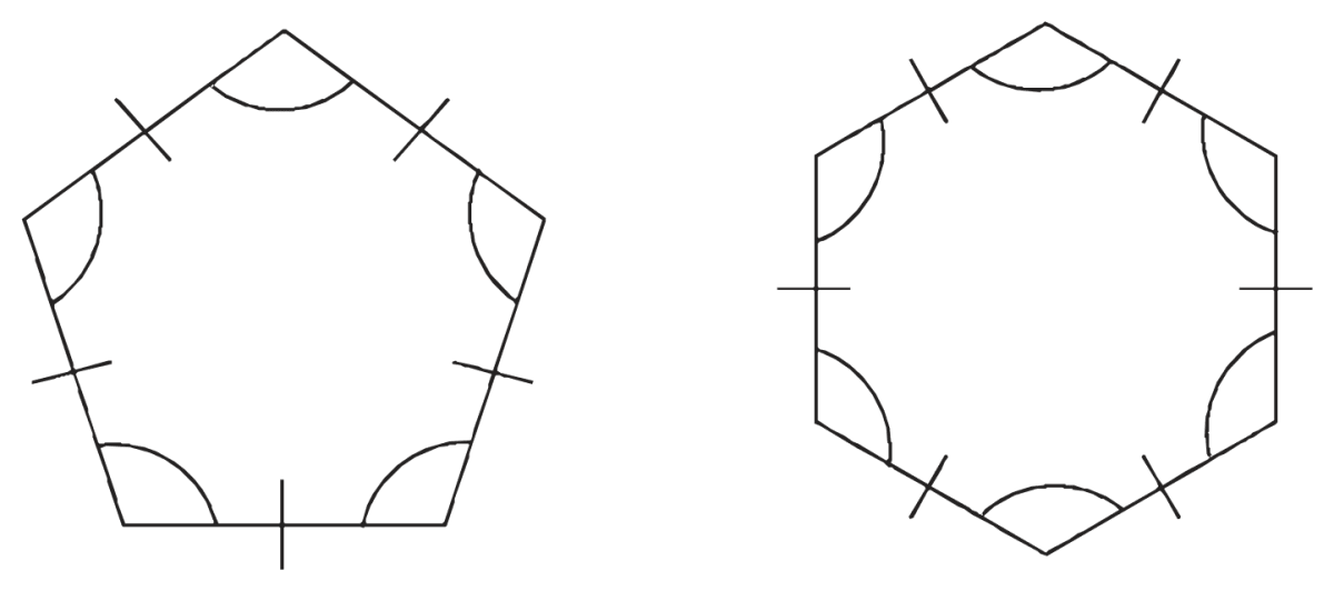
Answer
A compass can transfer a length exactly, so equal sides are easy to obtain.
Steps of construction:
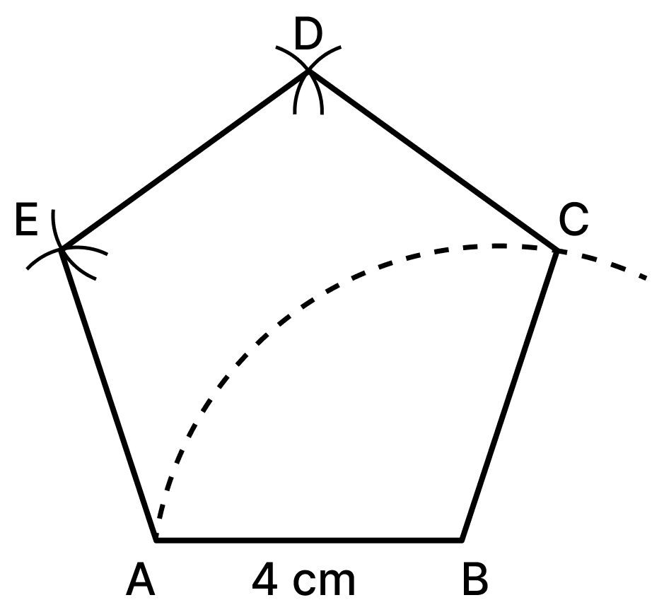
- Draw a line segment AB of any convenient length, say 4 cm.
- Open the compass to the length AB and keep this opening fixed throughout.
- From B, cut an arc and mark a point C on it. Join BC. Then BC = AB.
- Continue in the same way to get D and E (and F for the hexagon), joining each new point to the previous one.
- Finally join the last point to A.
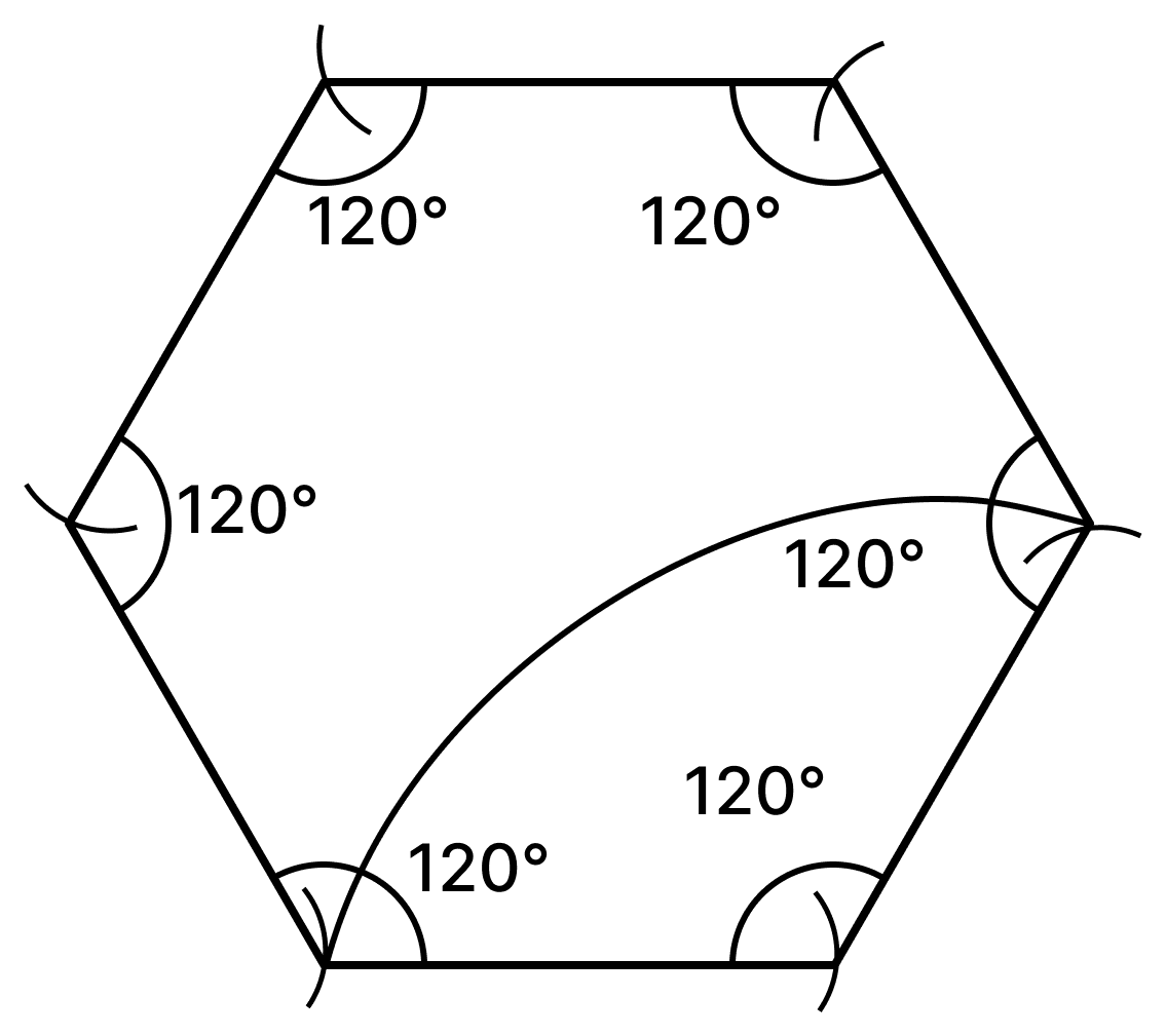
This gives a closed 5-sided figure (pentagon) or 6-sided figure (hexagon) with all sides equal. However, the angles obtained at the vertices need not be equal, so the figure is equilateral but not necessarily regular. To make it regular, the angle at each vertex must also be fixed:
- For a regular hexagon, each interior angle must be 120°, and 120° can be constructed with a ruler and compass because 120° = 60° + 60° and a 60° angle comes from an equilateral triangle.
- For a regular pentagon, each interior angle must be 108°, which cannot be obtained from 60° and 90° by repeated bisection. Its construction needs a deeper study of triangles and pentagons, which is taken up in later classes.
Hence, a hexagon with equal sides and equal angles can be constructed with a ruler and a compass, whereas the construction of a regular pentagon requires ideas beyond the present chapter.
Can we break a regular hexagon into smaller pieces that can be constructed?
Answer
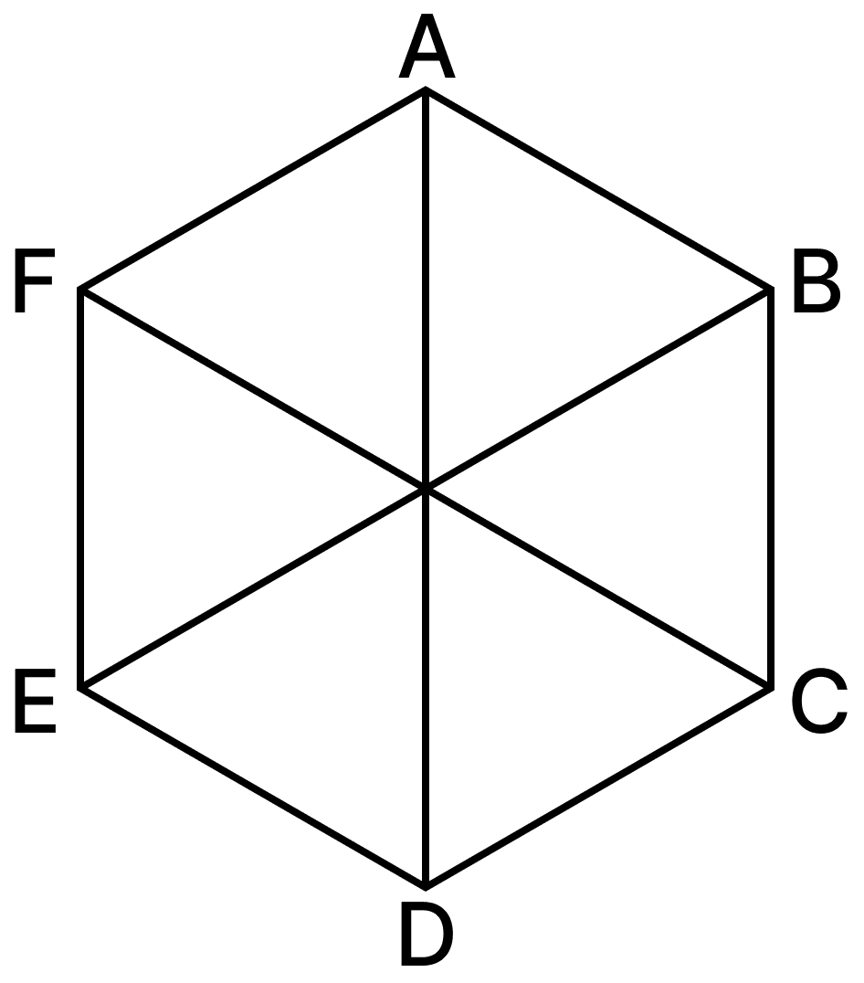
Yes. Join the centre O of the regular hexagon ABCDEF to each of its six vertices. The hexagon is then split into six triangles — △OAB, △OBC, △OCD, △ODE, △OEF and △OFA.
By symmetry, all these six triangles are congruent, and each of them turns out to be an equilateral triangle. An equilateral triangle is one of the simplest figures to construct with a ruler and a compass, since all three sides are equal and can be cut off with one fixed compass opening.
So instead of constructing the hexagon directly, we can construct six congruent equilateral triangles and place them around a common point.
Hence, a regular hexagon can be broken into six congruent equilateral triangles, each of which is easily constructible.
Can six congruent equilateral triangles be placed together as in Fig. 6.12? If yes, will it result in a regular hexagon?
Answer
Yes, they can be placed together in exactly this way.
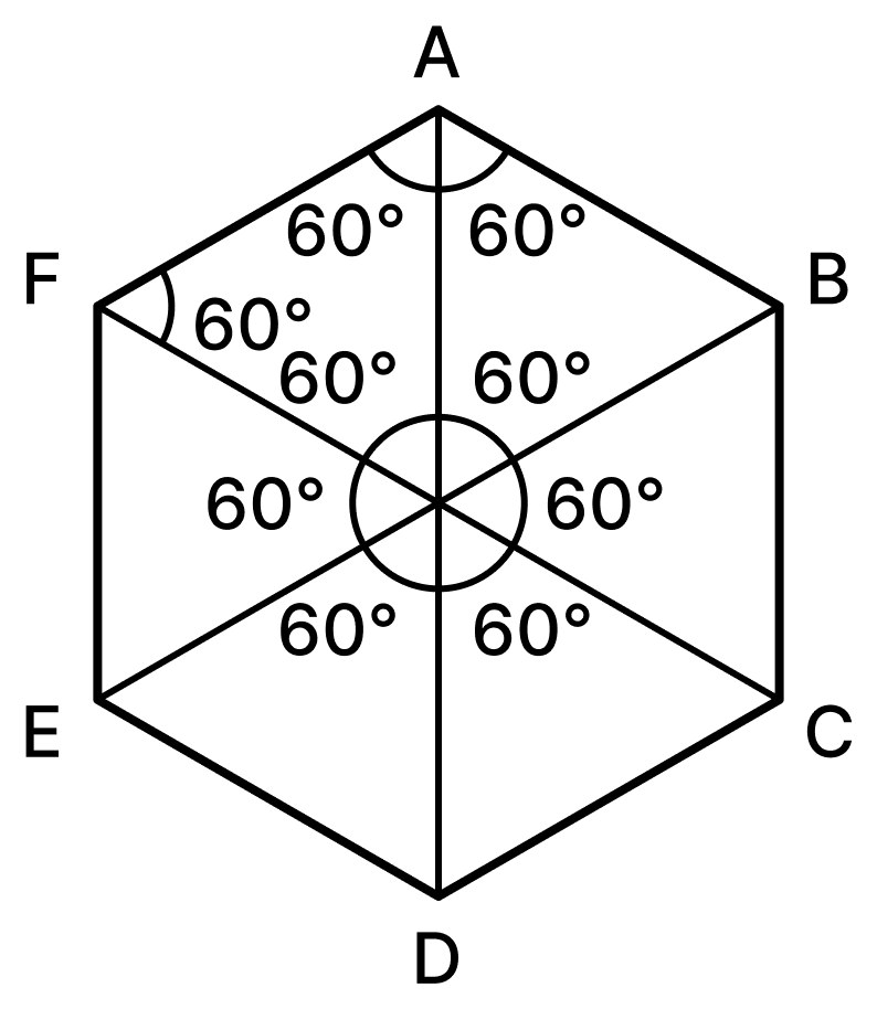
Each angle of an equilateral triangle is 60°. If six such triangles are placed with one vertex of each at the common point O, then the sum of the angles around O is
6 × 60° = 360°
Since the complete angle around a point is 360°, the six angles exactly fill the region around O — they neither overlap one another nor leave any gap.
Now examine the figure ABCDEF so formed.
- Its six sides AB, BC, CD, DE, EF and FA are the outer sides of the six congruent triangles, so all six sides are equal.
- Each angle of the hexagon, such as ∠FAB, is made up of two angles of triangles, one from △OFA and one from △OAB. So
∠FAB = 60° + 60° = 120°
Thus all six angles of the figure are equal to 120°.
∴ The figure has all sides equal and all angles equal.
Hence, six congruent equilateral triangles can indeed be placed together, and the resulting figure is a regular hexagon.
Consider this figure. Will the 70° angle fit into the gap? What is the gap angle ∠AOI?
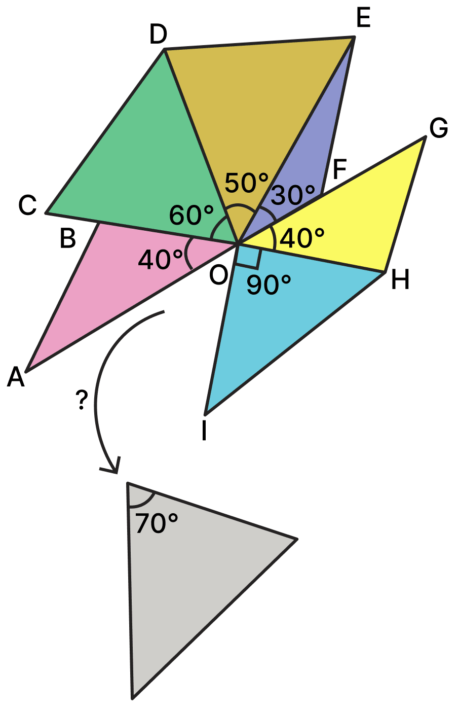
Answer
All the angles placed around the point O, together with the gap angle, must make up a complete angle of 360°.
The angles placed around O are 40°, 60°, 50°, 30°, 40° and 90°.
40° + 60° + 50° + 30° + 40° + 90° + gap angle = 360°
⇒ 310° + ∠AOI = 360°
⇒ ∠AOI = 360° - 310°
⇒ ∠AOI = 50°
The gap angle is 50°, but the given triangle has an angle of 70°, and 70° > 50°. So the 70° angle is too large for the gap — it would overlap the neighbouring angles.
∴ The gap angle ∠AOI is 50°, and the 70° angle will not fit into the gap.
In Fig. 6.12 can you explain why AOD, BOE and COF are straight lines?
Answer
In fig, the six triangles around the centre O are congruent equilateral triangles, so each of the angles at O is 60°.
For A, O and D:
∠AOD = ∠AOB + ∠BOC + ∠COD
⇒ ∠AOD = 60° + 60° + 60°
⇒ ∠AOD = 180°
Since ∠AOD is a straight angle, the rays OA and OD point in exactly opposite directions, and so A, O and D lie on one straight line.
In the same way,
∠BOE = ∠BOC + ∠COD + ∠DOE = 60° + 60° + 60° = 180°
∠COF = ∠COD + ∠DOE + ∠EOF = 60° + 60° + 60° = 180°
Hence, AOD, BOE and COF are each straight angles, and so AOD, BOE and COF are straight lines.
Construct a regular hexagon with a sidelength 4 cm using a ruler and a compass.
Answer
Steps of construction:
- Mark a point O and, with O as centre and radius 4 cm, draw a circle.
- Mark any point A on this circle.
- Keeping the same compass opening of 4 cm, with A as centre, cut the circle at B.
- With B as centre and the same radius 4 cm, cut the circle at C.
- Continuing in the same way, with C, D and E as centres, cut the circle at D, E and F respectively. The sixth arc from F falls exactly on A.
- Join AB, BC, CD, DE, EF and FA.
- Erase the supporting circle.
Then ABCDEF is the required regular hexagon of side 4 cm.
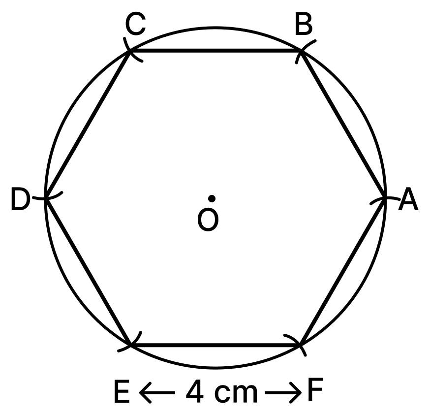
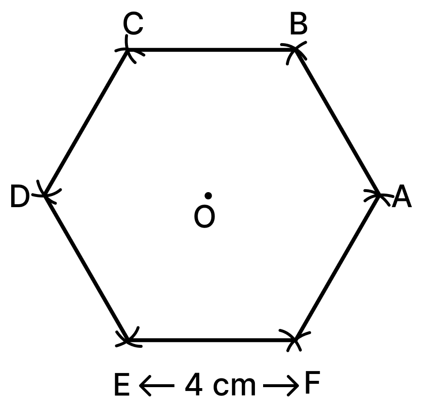
Justification: OA = OB = 4 cm (radii) and AB = 4 cm (compass opening), so △OAB is equilateral and ∠AOB = 60°. The same holds for each of the six triangles, so the six central angles add up to 6 × 60° = 360°, all six sides equal 4 cm and each angle of the hexagon is 60° + 60° = 120°.
Hence, the required regular hexagon of sidelength 4 cm is constructed using only a ruler and a compass.
Why is ∠CAX = 60°? Is there an equilateral triangle here?
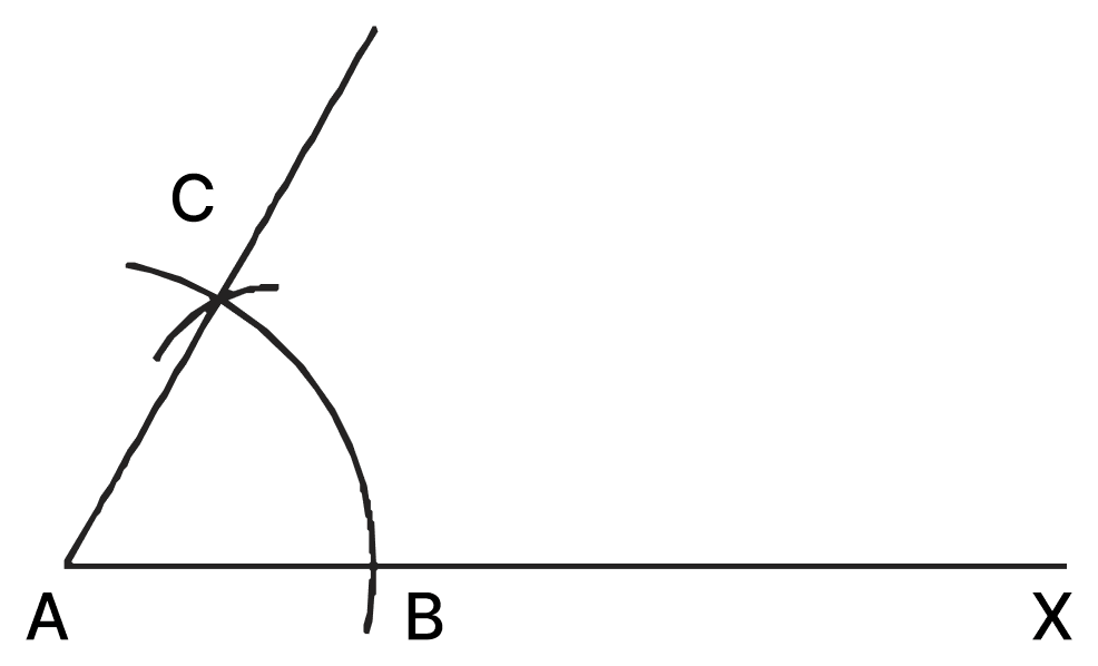
Answer
Yes, there is an equilateral triangle here. Join B and C.
The arc from A and the arc from B were drawn with the same radius. Therefore —
AB = radius (B lies on the arc drawn with centre A)
AC = radius (C lies on the arc drawn with centre A)
BC = radius (C lies on the arc drawn with centre B)
∴ AB = BC = CA, and so △ABC is an equilateral triangle.
In △ABC, angles opposite equal sides are equal.
∠A = ∠B = ∠C
∠A = ∠B = ∠C = 180°
⇒ 3 × ∠A = 180°
⇒ ∠A = 60°
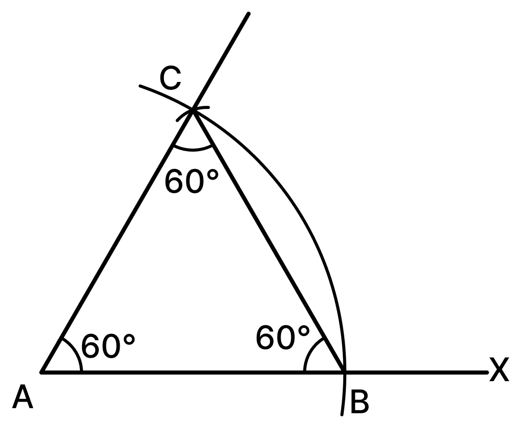
Hence, ∠CAX = ∠CAB = 60°, and △ABC is the equilateral triangle in the figure.
Construct a regular hexagon of sidelength 5 cm.
Answer
Steps of construction:
- Draw a circle with centre O and radius 5 cm.
- Mark any point A on the circle.
- With A as centre and the same radius 5 cm, draw an arc cutting the circle at B.
- With B as centre and radius 5 cm, cut the circle at C.
- Continuing in the same way from C, D and E, mark the points D, E and F. The sixth arc falls exactly on A.
- Join AB, BC, CD, DE, EF and FA.
- Erase the supporting circle.
ABCDEF is the required regular hexagon.
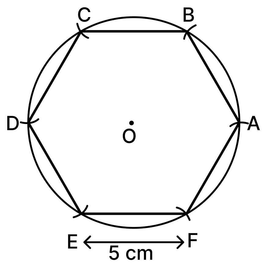
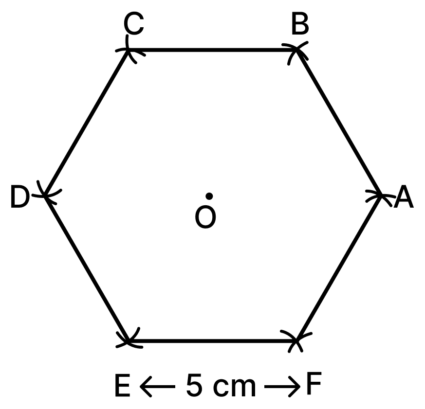
Why this works:
In △OAB, OA = OB = AB = 5 cm, so △OAB is equilateral and ∠AOB = 60°. The same is true of the other five triangles at the centre. Six such angles give
6 × 60° = 360°
so the six arcs close up exactly around O without gaps or overlaps. Each interior angle of the figure is 60° + 60° = 120°, and all six sides are 5 cm.
Hence, ABCDEF is a regular hexagon of sidelength 5 cm.
How will you construct 30° and 15° angles?
Answer
A 30° angle is half of 60°, and a 15° angle is half of 30°. So we first construct a 60° angle and then bisect it twice.
Steps of construction:
- Draw a line segment AX and construct ∠CAX = 60°.
- With A as centre and any convenient radius, draw an arc cutting AX at P and AC at Q.
- With P as centre and a radius more than half of PQ, draw an arc inside the angle.
- With Q as centre and the same radius, draw another arc cutting the previous arc at R.
- Join A and R.
∠RAX = = 30° is the required angle.
- Now with A as centre and any convenient radius, draw an arc cutting AX at S and AR at T.
- With S and T as centres and a radius more than half of ST, draw two arcs cutting each other at U.
- Join A and U.
∠UAX = = 15° is the required angle.
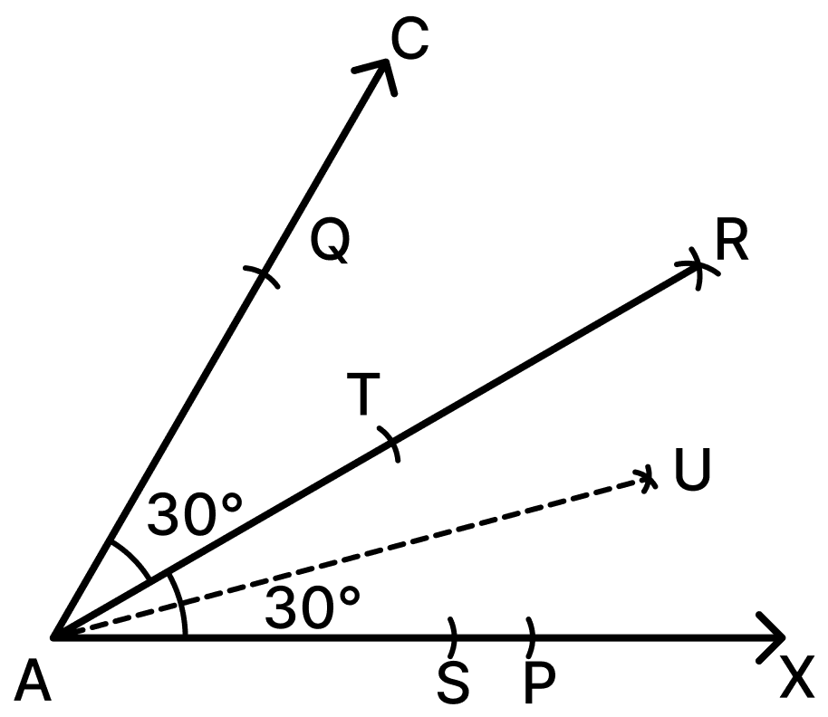
Hence, 30° and 15° angles are obtained by bisecting a 60° angle once and twice respectively.
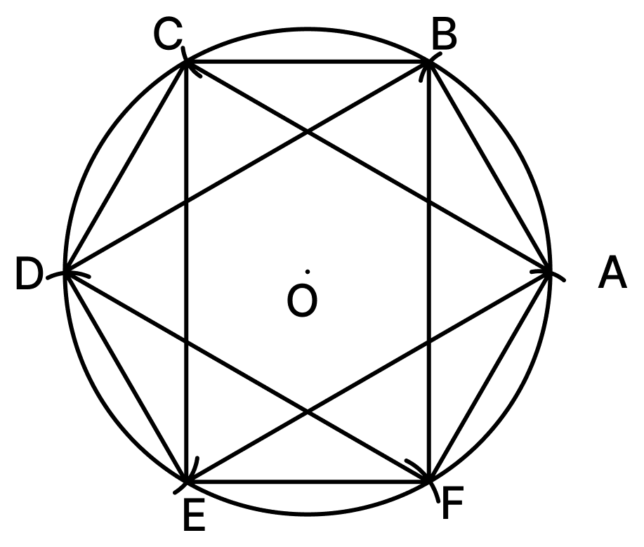
Construct the following 6-pointed star. Note that it has a rotational symmetry.
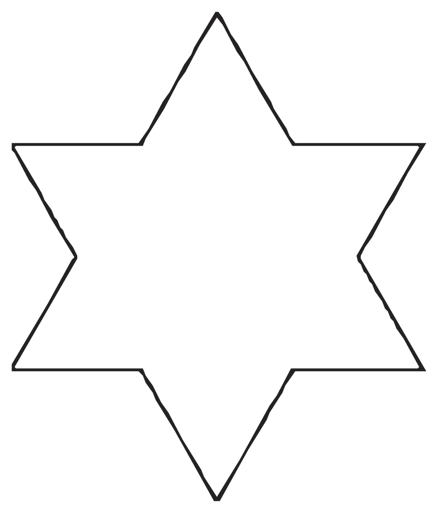
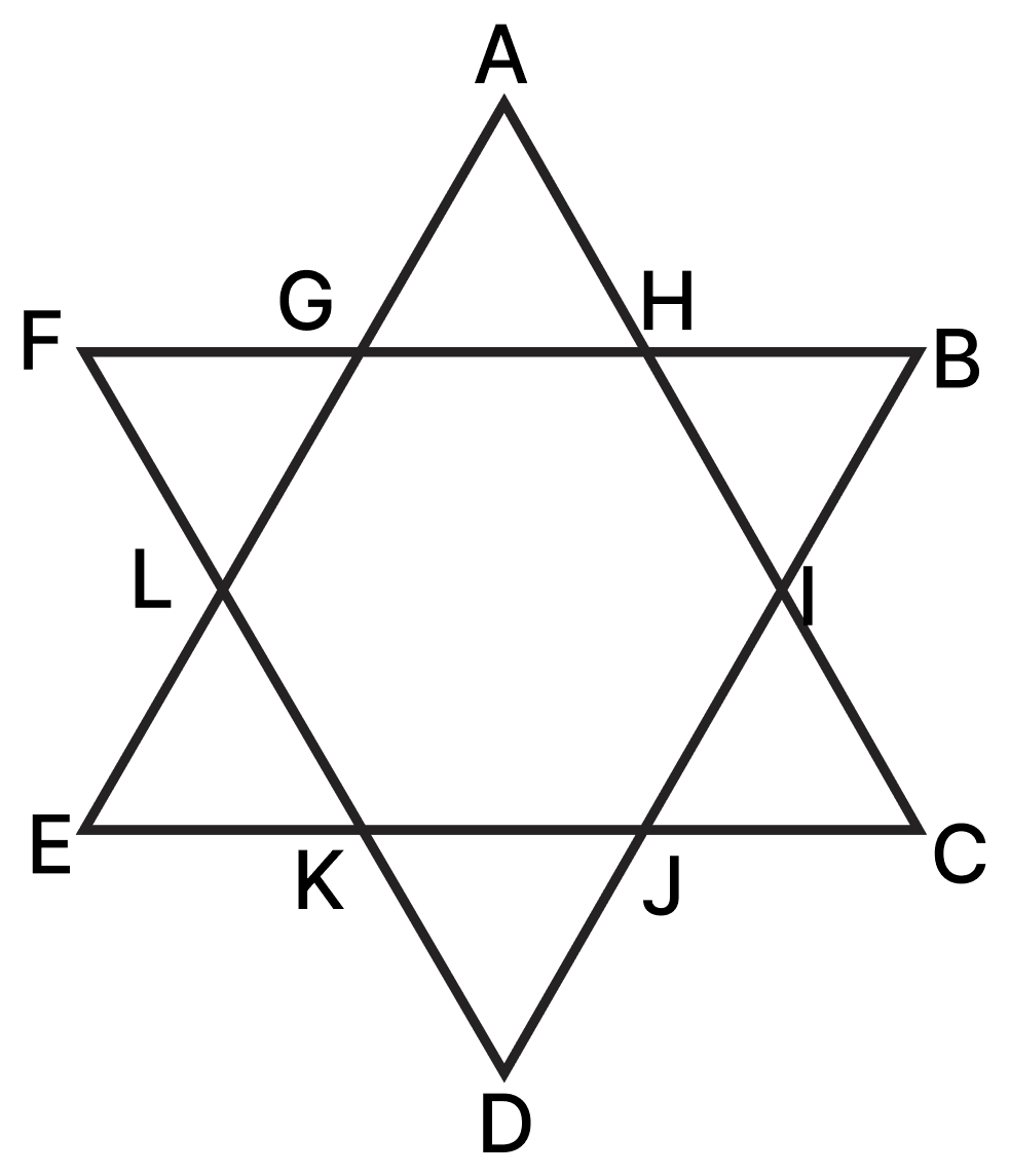
(i) Are the six triangles forming the 6 points of the star — △AGH, △BHI, △CIJ, △DJK, △ELK, △FLG — equilateral? Why?
[Hint: Find the angles.]
Answer
Yes — the star is made of a regular hexagon GHIJKL with an equilateral triangle standing on each of its sides. The whole star is the overlap of two equilateral triangles △ACE and △BDF.
Steps of construction:
- Draw a circle with centre O and any convenient radius r.
- Mark a point A on the circle. With A as centre and radius r, cut the circle at B. Continuing in the same way, mark C, D, E and F, so that the six points are equally spaced on the circle.
- Join A, C and E to get the equilateral triangle △ACE.
- Join B, D and F to get the equilateral triangle △BDF.
- The two triangles cross each other at six points. Name them G, H, I, J, K and L in order; GHIJKL is a regular hexagon.
- Rub out the supporting circle.
The remaining outline A–H–B–I–C–J–D–K–E–L–F–G–A is the required 6-pointed star.
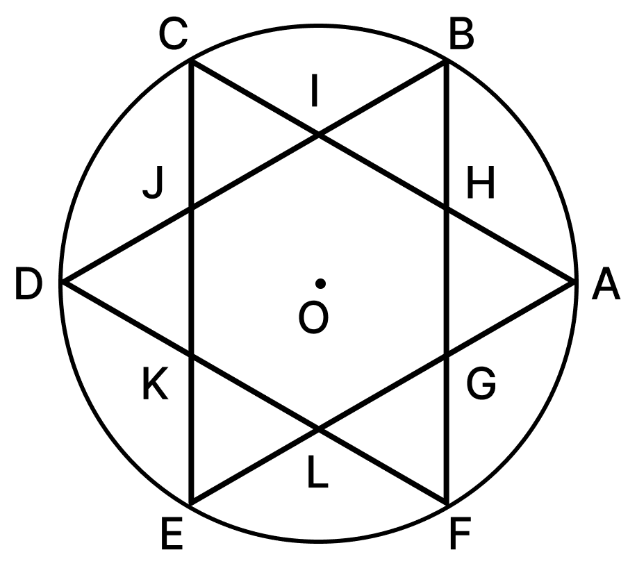
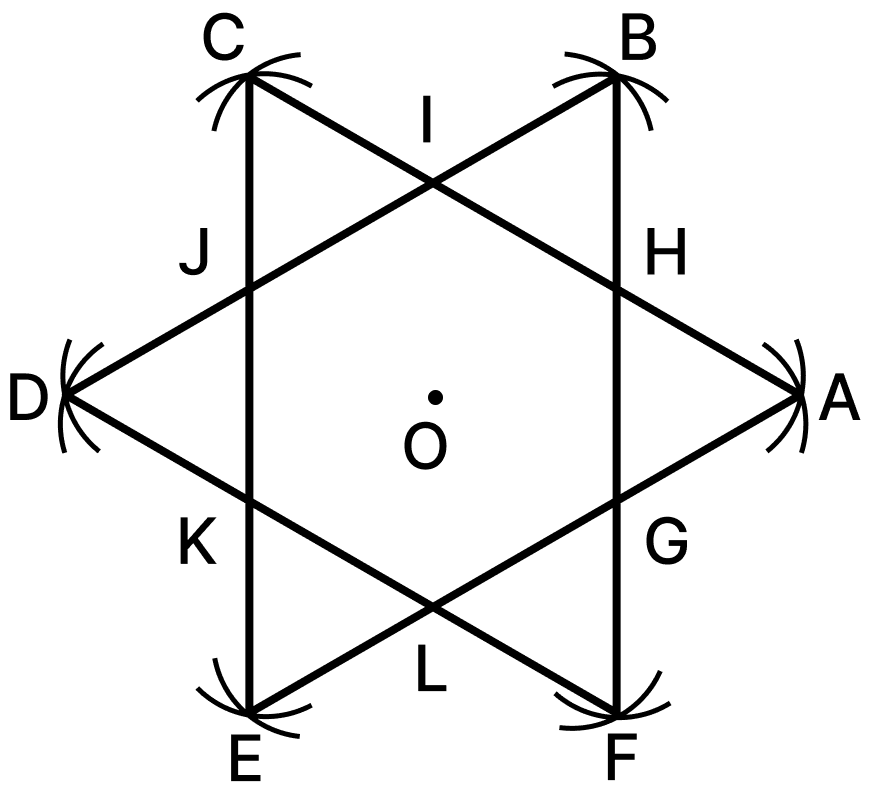
The figure looks exactly the same after a rotation of = 60° about O.
Hence, the 6-pointed star is constructed, and it has rotational symmetry of order 6.
(i)
Yes, all the six triangles are equilateral.
GHIJKL is a regular hexagon, so the sum of its interior angles is
(6 − 2) × 180° = 720°
⇒ each interior angle =
Consider the point △AGH.
A, G, L and E lie on the side AE of △ACE, so AGL is a straight line.
∠AGH + ∠HGL = 180°
⇒ ∠AGH = 180° - 120° = 60°
A, H, I and C lie on the side AC of △ACE, so AHI is a straight line.
∠AHG + ∠GHI = 180°
⇒ ∠AHG = 180° - 120° = 60°
In △AGH,
∠GAH = 180° − (60° + 60°)
⇒ ∠GAH = 60°
All three angles of △AGH are 60°, so it is equiangular and therefore equilateral.
The same reasoning applies at each of the other five vertices of the hexagon, since every interior angle of the hexagon is 120° and every side of the two big triangles is a straight line.
Hence, △AGH, △BHI, △CIJ, △DJK, △ELK and △FLG are all equilateral triangles.
Construct the following figures:
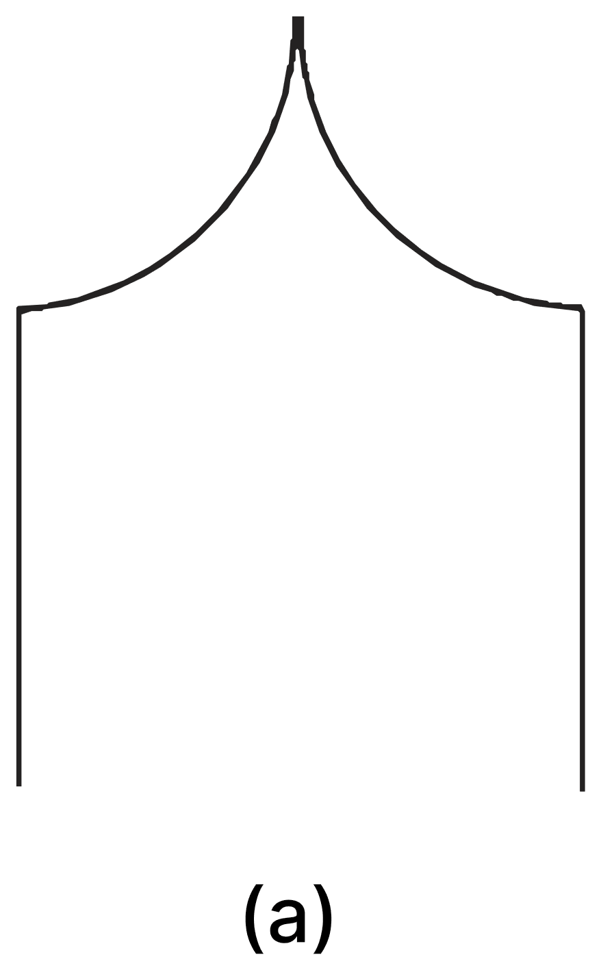
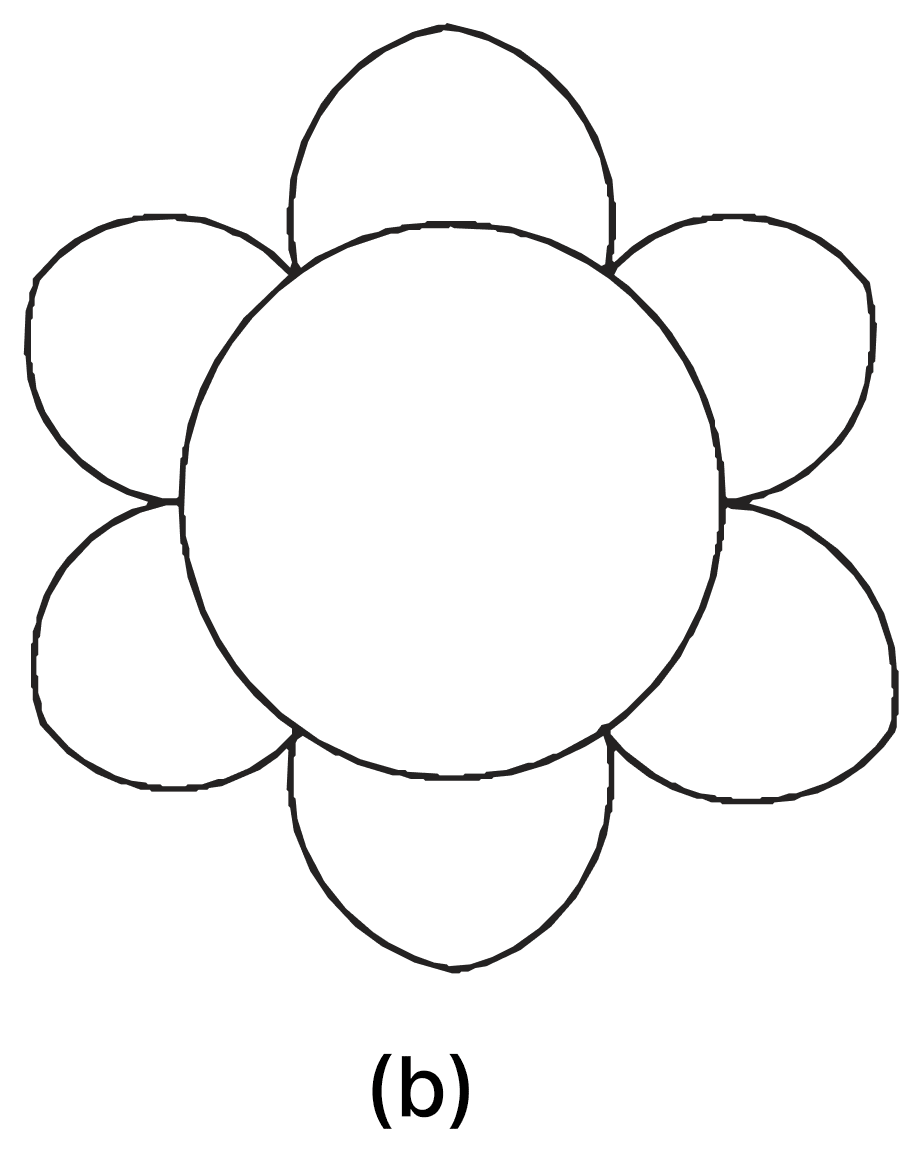
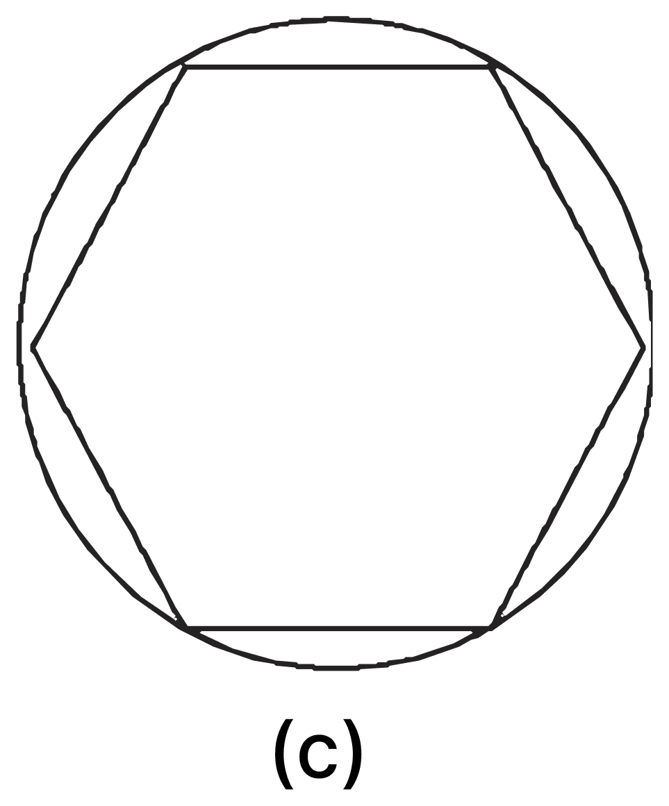
Answer
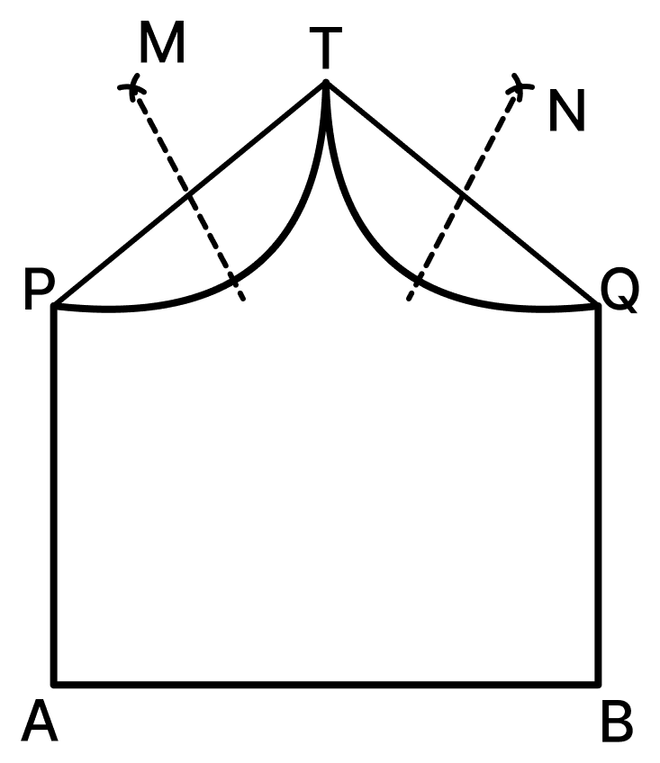
(a) An Inflexed Arc
The supporting lines are two vertical segments of equal length with two equal slanting segments above them, as in Fig. 6.11.
Steps of construction:
Draw a line segment AB for the width of the figure.
At A and B, construct perpendiculars to AB and mark P and Q on them such that AP = BQ.
Join P and Q to a point T above, taking PT = QT. PT and QT are the supporting lines.
Taking a radius more than half of PT, draw arcs from P and from T cutting each other at M, on the right of PT. With M as centre and radius MP, draw the arc from P to T.
Taking a radius more than half of QT, draw arcs from Q and from T cutting each other at N, on the right of QT. With N as centre and radius NQ, draw the arc from Q to T.
Rub out the supporting lines PT and QT, and darken AP, BQ and the two arcs.
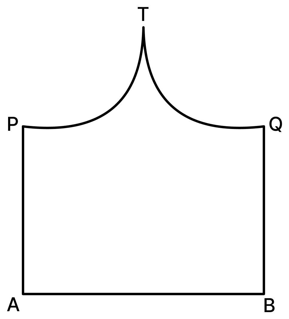
Different arches are obtained by changing the radii of the arcs.
(b) A six-petalled flower
This design can be constructed with one fixed compass opening.
Steps of construction:
- Draw a circle with centre O and radius r.
- Mark a point A on the circle. With A as centre and the same radius r, cut the circle at B. Continuing in the same way, mark C, D, E and F.
- With each of A, B, C, D, E and F as centre and the same radius r, draw a complete circle.
- Each pair of neighbouring circles meets in a lens-shaped region. Darken the part of each such region lying outside the first circle — these are the six petals — and darken the first circle.
- Rub out the remaining arcs.
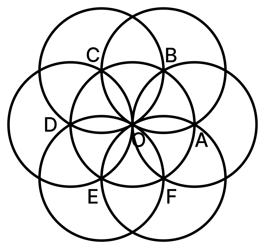
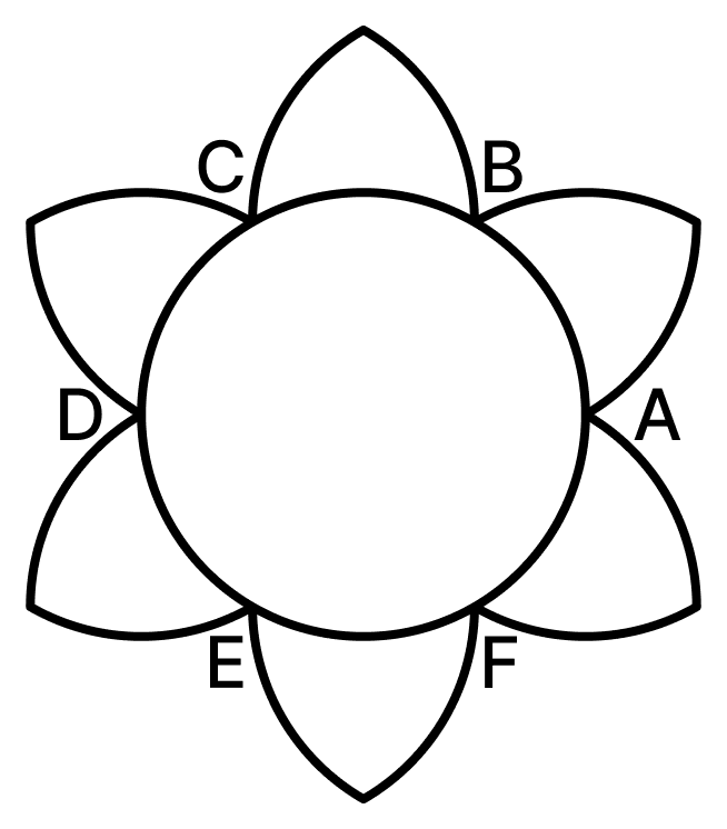
Hence, the six-petalled flower can be constructed using one fixed compass setting.
(c) A regular hexagon inscribed in a circle
Steps of construction:
- Draw a circle with centre O and radius r.
- Mark any point A on the circle.
- Keeping the compass opening equal to r, step off six points A, B, C, D, E and F successively around the circle.
- Join AB, BC, CD, DE, EF and FA.
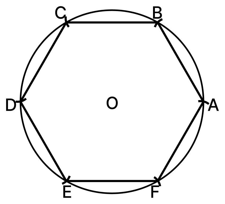
Hence, ABCDEF is the required regular hexagon inscribed in the circle.
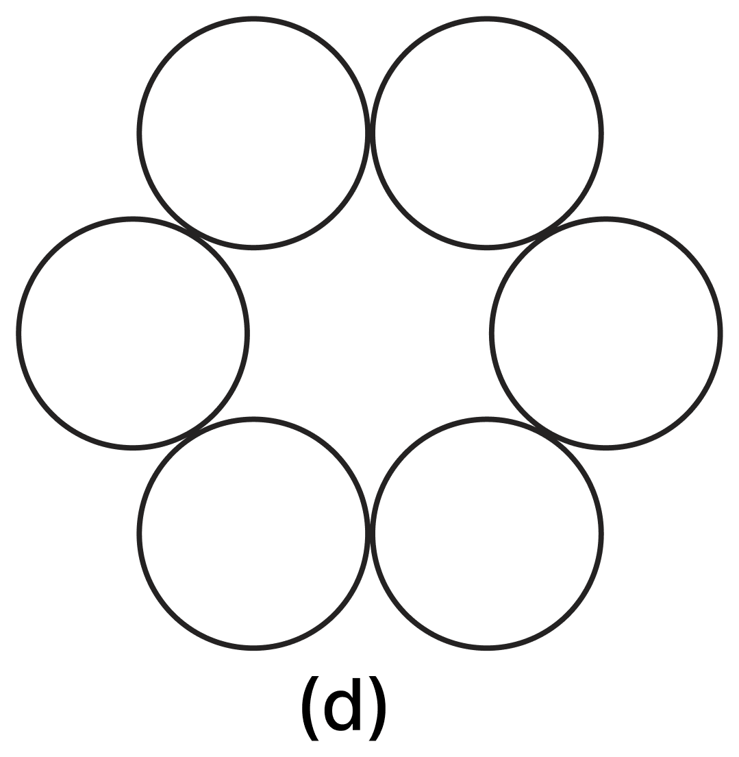
(d) A ring of six equal circles
Steps of construction:
- Draw a supporting circle with centre O and radius R.
- Mark six points A, B, C, D, E and F on it at intervals of R, as in the hexagon construction.
- Construct the perpendicular bisector of OA to get a length equal to .
- With each of A, B, C, D, E and F as centre and radius , draw a circle.
- Rub out the supporting circle.
Two neighbouring centres are R apart and each circle has radius , and
so every circle just touches its two neighbours.
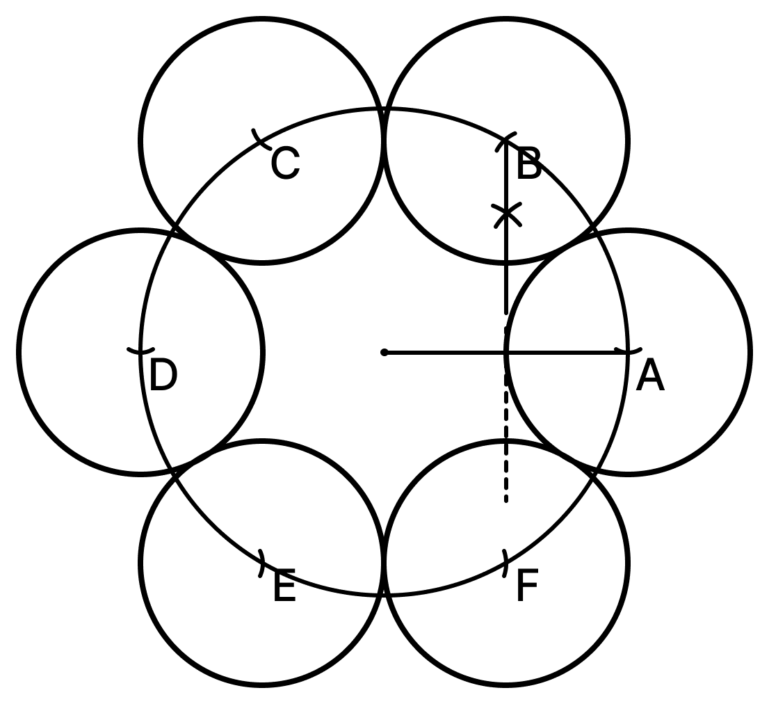
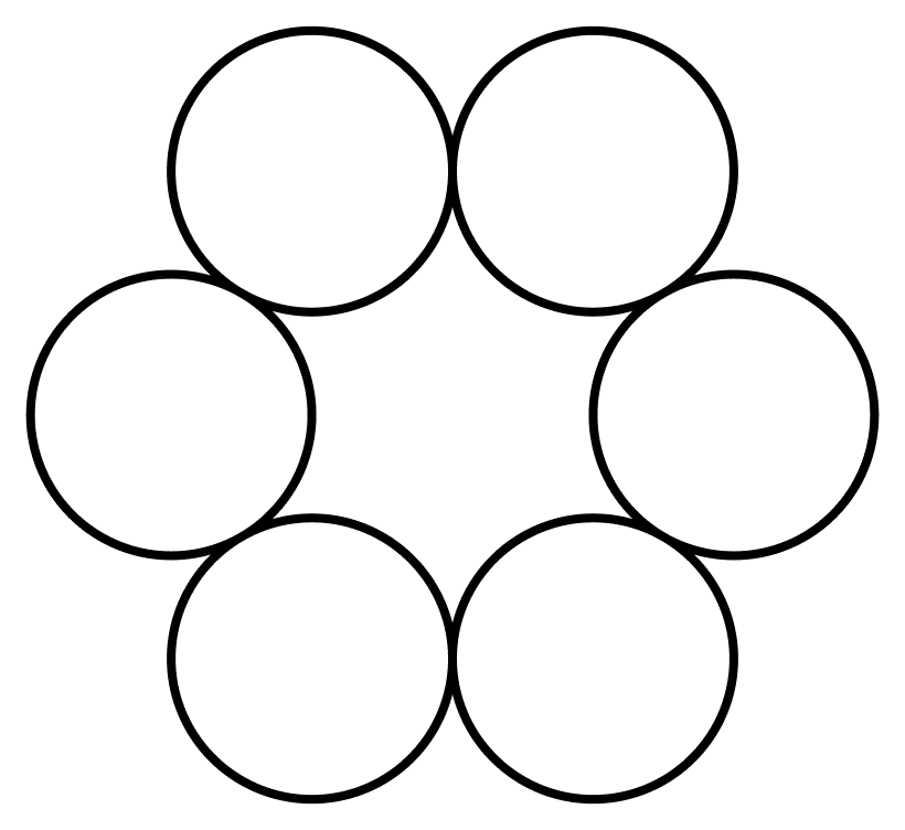
Hence, six equal circles are obtained, each touching the next.
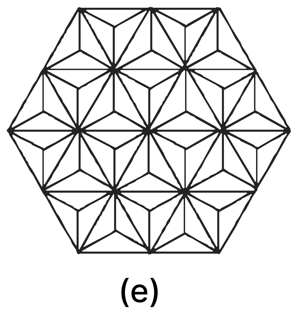
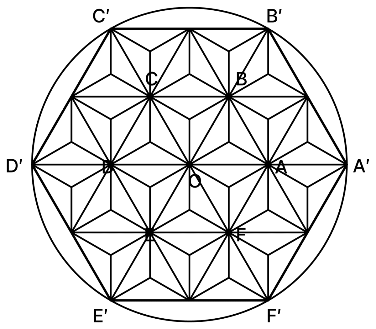
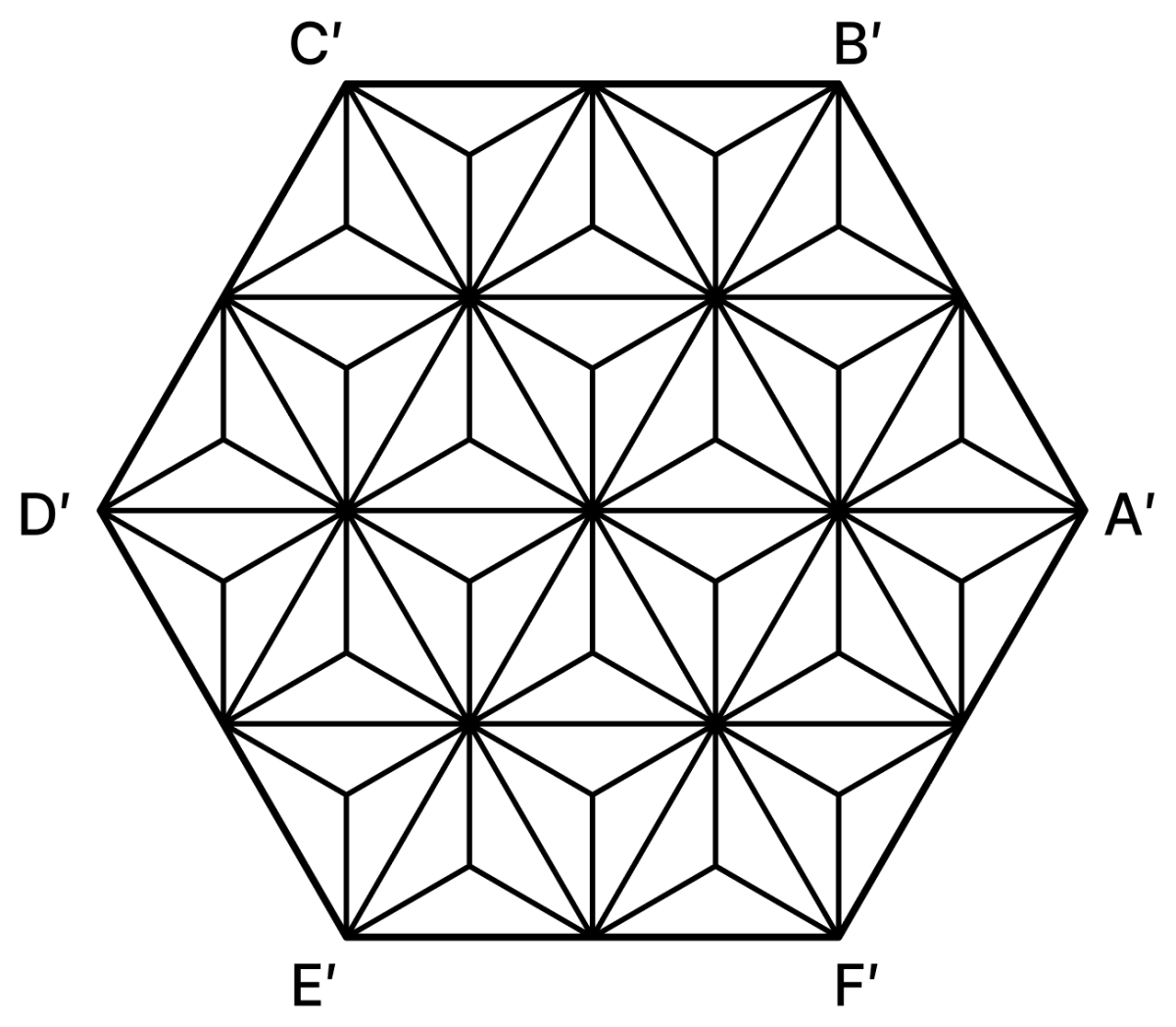
(e) A hexagon filled with a triangular star pattern
Steps of construction:
- Draw a circle with centre O and any convenient radius.
- Mark any point A on the circle. With A as centre and radius OA, draw an arc cutting the circle at B.
- With B as centre and the same radius, draw an arc cutting the circle at C. Continue in the same way to obtain the equally spaced points D, E and F on the circle.
- Join the points A, B, C, D, E and F successively to obtain a regular hexagon.
- Join the opposite vertices AD, BE and CF. These three diagonals meet at the centre O.
- Draw a circle with centre O and radius twice OA. Join OA and extend it to intersect the outer circle at A'. Similarly, draw other extended lines. Join the lines as shown in the figure.
- There are 5, 7, 7 and 5 triangles in the 1st, 2nd, 3rd and 4th rows respectively.
- Join the vertices of each triangle to the centre of the respective triangle.
- Erase the unnecessary construction lines, the outer circle and the point labels, and darken the required lines.
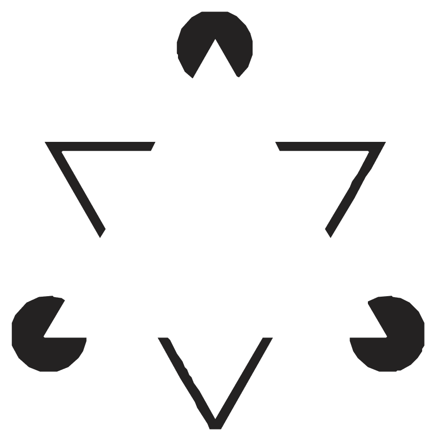
Optical Illusion: Do you notice anything interesting about the following figure? How does this happen? Recreate this in your notebook.
Answer
What we notice:
We seem to see a bright white triangle pointing upwards, lying on top of a second triangle that points downwards. But neither triangle has actually been drawn — no side of the white triangle is present in the figure.
How this happens:
The three black circles each have a 60° wedge cut out of them, and the three open corners each show a 60° angle. Our eyes join the ends of these cut edges and 'complete' the missing sides. Such imagined edges are called illusory contours, and they make the white triangle look brighter than the paper around it, even though it is exactly the same white.
Steps of construction (to recreate it):
- Draw a circle with centre O and any convenient radius. Mark six points A, B, C, D, E and F on it at intervals of the radius.
- Join A, C, E to get an equilateral triangle pointing upwards, and B, D, F to get one pointing downwards. These are only supporting lines.
- At A, C and E, draw three equal small circles. From each of them, cut out the wedge lying inside the angle of △ACE — the arms of the wedge are the 60° angle of the triangle. Shade the rest of each circle black.
- Erase all the supporting lines.
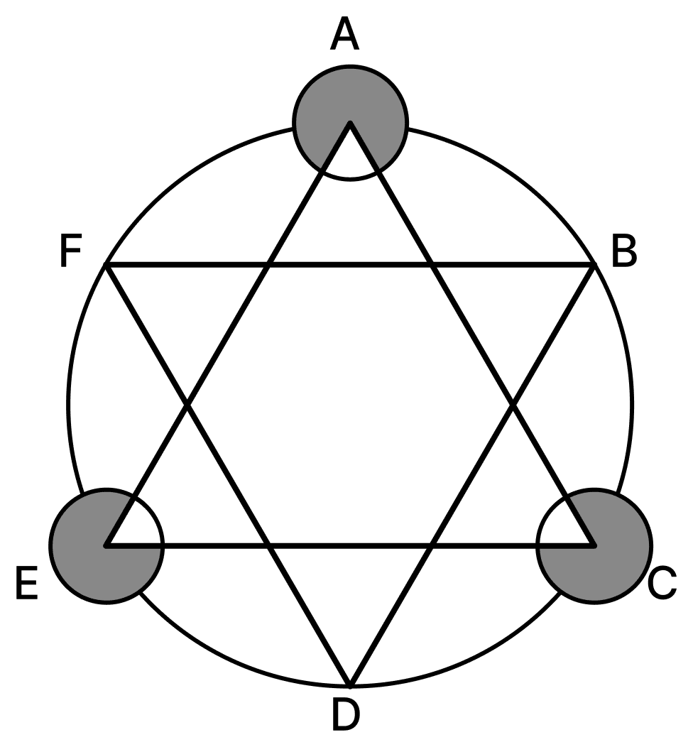
Hence, the white triangle that we 'see' is created entirely by our eyes.
Construct this figure.
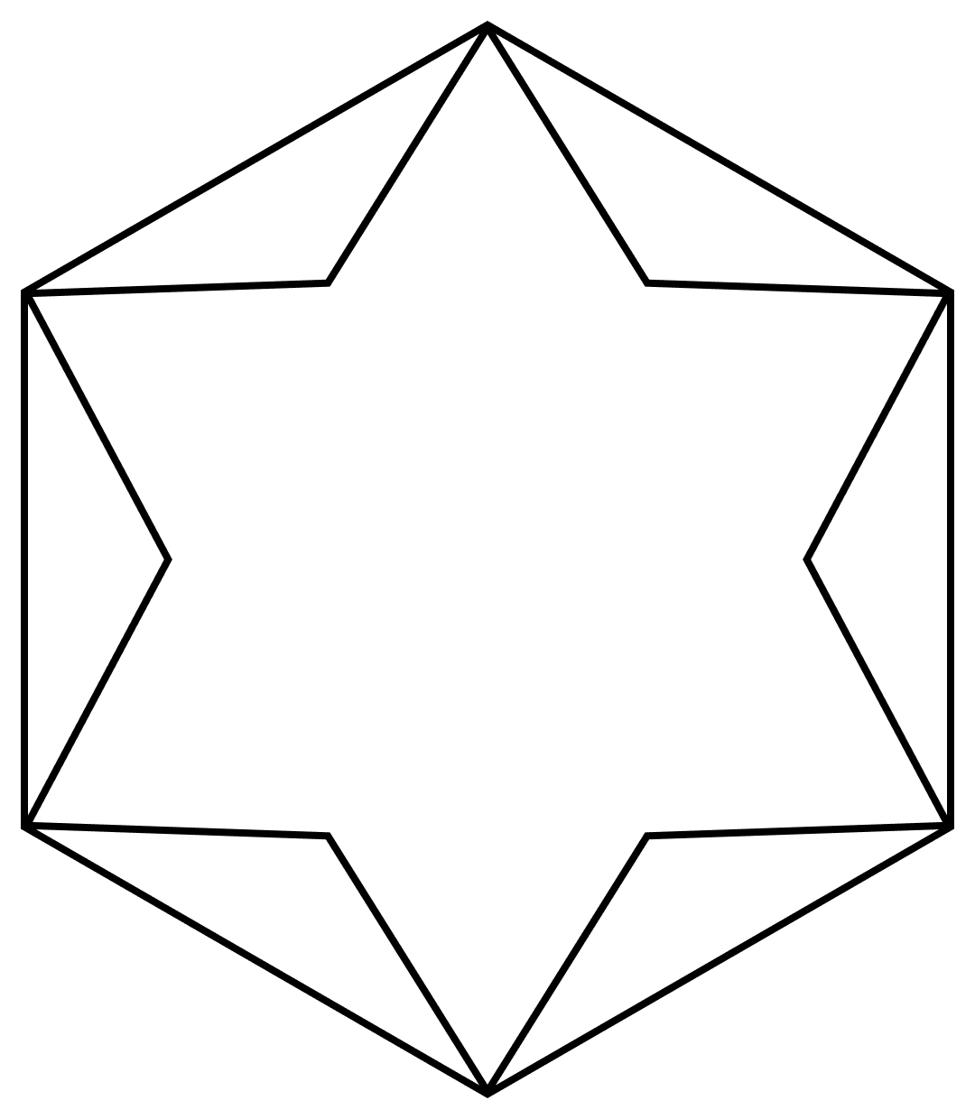
[Hint: Find the angles in this figure.]
Answer
The figure is a regular hexagon with a 6-pointed star inside it, the six points of the star touching the six vertices of the hexagon.
The angles needed are:
- each interior angle of the regular hexagon = 120°,
- each angle of the two big triangles of the star = 60°.
Steps of construction:
- Draw a circle with centre O and any convenient radius r.
- Mark a point A on the circle and, with the same radius r, step off B, C, D, E and F round the circle.
- Join AB, BC, CD, DE, EF and FA to get the regular hexagon ABCDEF.
- Join A, C, E to get one equilateral triangle and B, D, F to get the other. Together they form the 6-pointed star, whose points are exactly the vertices of the hexagon.
- Erase the supporting circle and if the plain star is wanted inside, the six sides of the inner hexagon formed by the crossing lines.
Hence, the required figure is constructed with a ruler and a compass alone.
Draw a line l and mark a point P anywhere outside the line. Construct a perpendicular to the given line l through P.
[Hint: Find a line segment on l whose perpendicular bisector passes through P.]
Answer
Steps of construction:
- Draw a line l and mark a point P outside it.
- With P as centre and any radius large enough, draw an arc cutting the line l at two points M and N.
- With M as centre and a radius more than half of MN, draw an arc on the other side of l.
- With N as centre and the same radius, draw another arc cutting the previous arc at Q.
- Join P and Q, meeting l at R.
PR ⟂ l, so PQ is the required perpendicular through P.
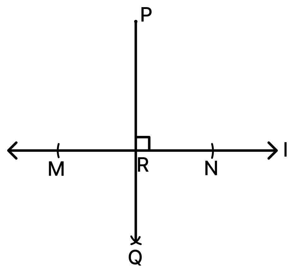
Why this works:
By construction PM = PN, so P is at the same distance from M and from N. Also QM = QN, so Q is at the same distance from M and from N. Any point that is at the same distance from M and N lies on the perpendicular bisector of MN. So both P and Q lie on the perpendicular bisector of MN, and two points fix a line.
Hence, PQ is the perpendicular bisector of MN and is therefore perpendicular to the line through P.
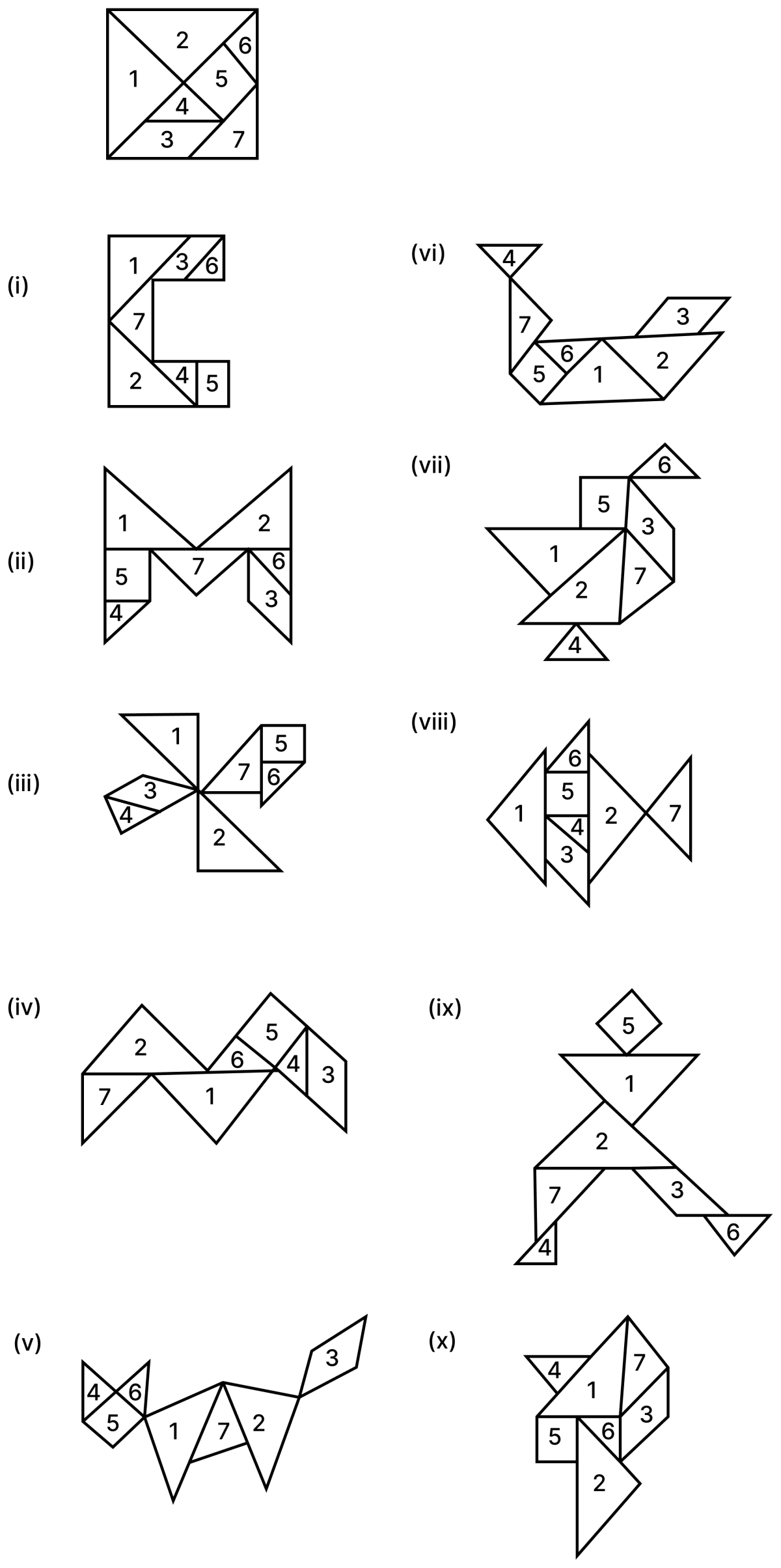
How can the tangram pieces be rearranged to form each of the following figures?
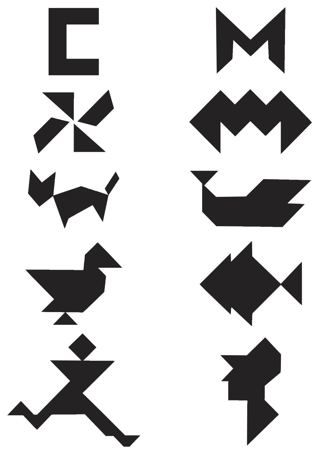
Answer
The square is cut into these 7 pieces:
- two large right-angled isosceles triangles,
- one medium right-angled isosceles triangle,
- two small right-angled isosceles triangles,
- one square,
- one parallelogram.
Two useful facts while solving these puzzles:
- Every figure uses all the 7 pieces, with no gaps and no overlaps. So each figure has exactly the same area as the original square, however different the figures may look.
- The two large triangles together cover half of the square. So it helps to place the two large triangles first, into the biggest parts of the outline, and then fit the medium triangle, the square and the parallelogram, keeping the two small triangles for the last narrow corners.
The pieces may be turned round or flipped over while being placed.
One arrangement for each figure is shown below.
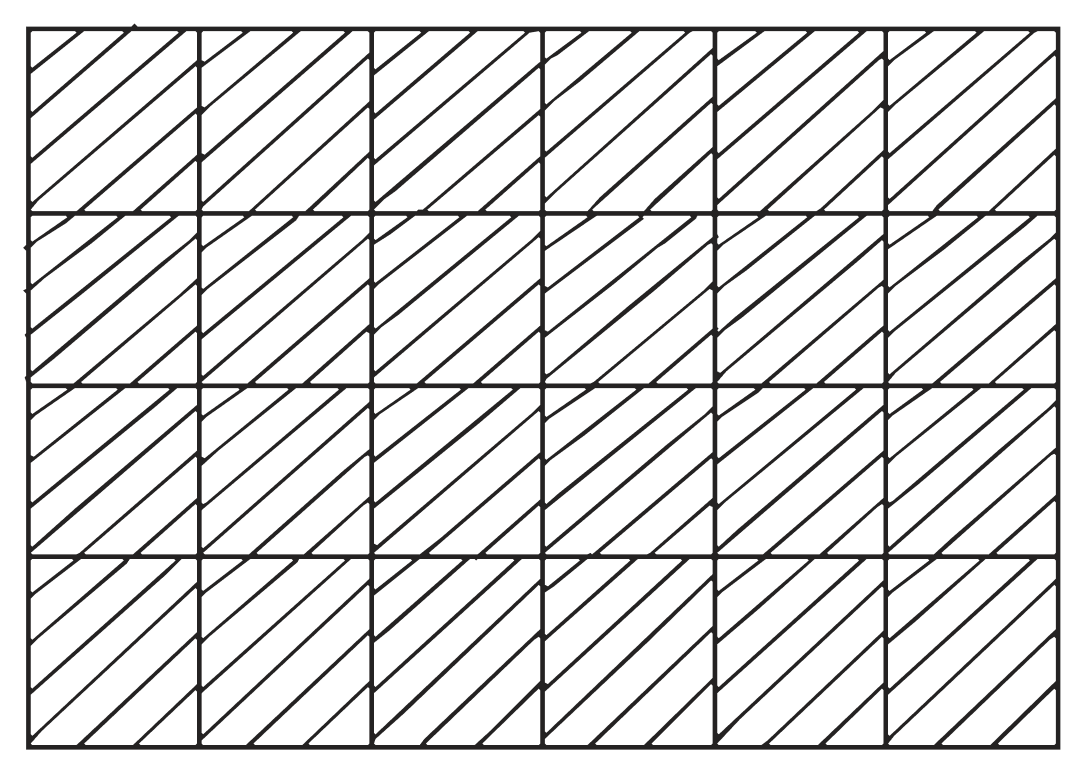
Can a 4 × 6 grid be tiled using multiple copies of 2 × 1 tiles? We are allowed to rotate a 2 × 1 tile and use it.
Answer
Yes, a 4 × 6 grid can be tiled using 2 × 1 tiles.
Number of unit squares in the grid = 4 × 6 = 24
Each tile covers 2 unit squares.
Number of tiles needed =
⇒ Number of tiles needed = 12
One simple way of tiling:
The grid has 4 rows, and 4 is an even number. So each column of 4 unit squares can be completely covered by 2 vertical tiles, one above the other. Doing this for all the 6 columns uses
2 × 6 = 12 tiles
and covers the whole grid without any gaps or overlaps.
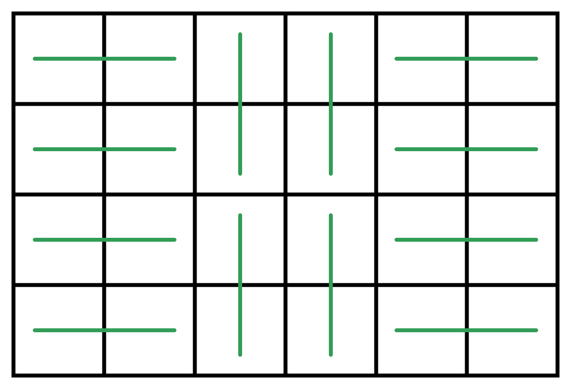
Hence, a 4 × 6 grid can be tiled with 12 tiles of size 2 × 1. This is of course not the only tiling possible.
Can a 4 × 7 grid be tiled using 2 × 1 tiles?
Answer
Yes, a 4 × 7 grid can be tiled using 2 × 1 tiles.
A 4 × 7 grid has 4 rows and 7 columns.
Since the number of rows is 4, which is even, every column of the grid contains an even number of unit squares. So each column can be completely covered by placing vertical tiles one below the other.
Number of unit squares in one column = 4
Number of vertical tiles needed for one column = 4 ÷ 2 = 2
Number of columns = 7
Total number of tiles = 2 × 7 = 14
These 14 tiles cover 14 × 2 = 28 unit squares, which is exactly the number of unit squares in the grid, since 4 × 7 = 28.
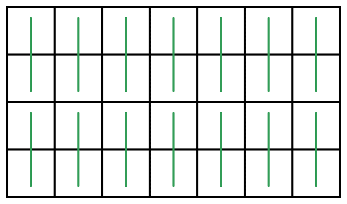
Hence, a 4 × 7 grid can be tiled using 14 tiles of size 2 × 1.
What about a 5 × 7 grid? Complete the justification.
Answer
A 5 × 7 grid cannot be tiled using 2 × 1 tiles.
Number of unit squares in the grid = 5 × 7 = 35
Number of unit squares covered by one tile = 2
Every tile covers exactly 2 unit squares, so any number of tiles will always cover an even number of unit squares. But 35 is an odd number.
Hence, a 5 × 7 grid cannot be tiled using 2 × 1 tiles.
Justification:
The 5 × 7 grid has 5 × 7 = 35 unit squares, and each tile covers exactly 2 unit squares.
Suppose the grid could be tiled using k tiles, where k is a whole number. Since the tiles do not overlap and leave no gaps, the number of unit squares covered by them must be exactly 35.
Number of unit squares covered by k tiles = 2k
⇒ 2k = 35
⇒ k =
But is not a whole number, so no such k exists.
In other words, 2k is always an even number, while 35 is an odd number, and an even number can never be equal to an odd number.
∴ There is no way to tile a 5 × 7 grid using 2 × 1 tiles.
Is an m × n grid tileable with 2 × 1 tiles, if one of m and n is even and the other is odd? If yes, come up with a general strategy to tile it.
Answer
Yes, the grid is tileable in this case as well. Only one of the two numbers needs to be even.
Case 1: m (the number of rows) is even and n (the number of columns) is odd
Each column has m unit squares, and m is even. So cover each column completely with vertical tiles, and repeat this for all n columns.
Total number of tiles =
Case 2: m (the number of rows) is odd and n (the number of columns) is even
Each row has n unit squares, and n is even. So cover each row completely with horizontal tiles, and repeat this for all m rows.
Total number of tiles =
In both cases mn is even, so is a whole number.
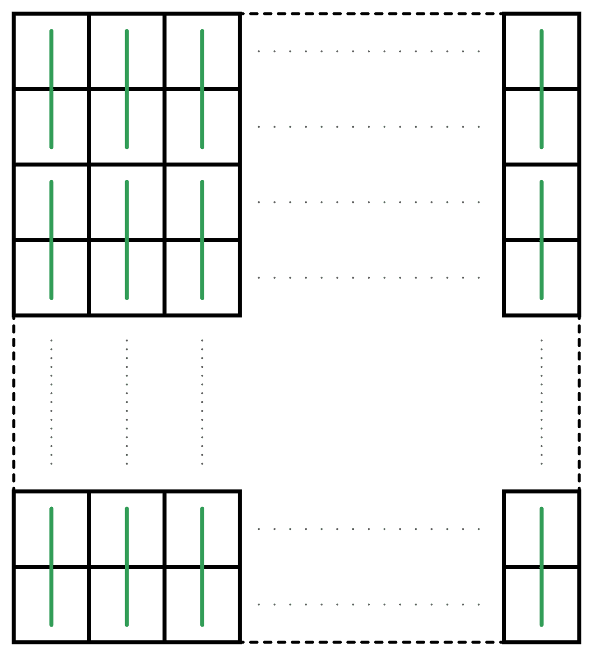
Hence, if at least one of m and n is even, the m × n grid can be tiled using tiles of size 2 × 1.
Is an m × n grid tileable with 2 × 1 tiles, if both m and n are odd? Give reasons.
Answer
No, an m × n grid is not tileable with 2 × 1 tiles when both m and n are odd.
Reason:
Number of unit squares in the grid = m × n
m is odd and n is odd
⇒ mn is odd (product of two odd numbers is odd)
Now, suppose the grid could be tiled using k tiles. Each tile covers exactly 2 unit squares, so the tiles together cover 2k unit squares, which is always an even number.
⇒ 2k = mn
This is impossible, because 2k is even while mn is odd.
∴ When both m and n are odd, the m × n grid can never be tiled with 2 × 1 tiles.
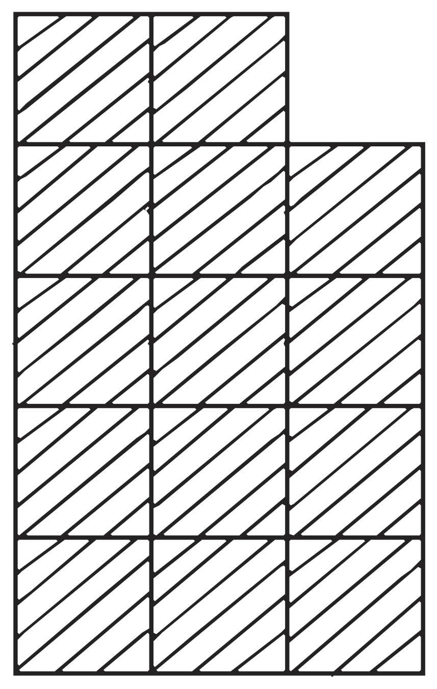
Here is a 5 × 3 grid, with a unit square removed. Now, it has an even number of unit squares. Is it tileable with 2 × 1 tiles?
Answer
Yes, this region is tileable with 2 × 1 tiles.
Number of unit squares in the 5 × 3 grid = 5 × 3 = 15
Number of unit squares removed = 1
Number of unit squares in the region = 15 - 1 = 14
Number of tiles required = 14 ÷ 2 = 7
Here, the square removed is the corner square of the top row. So the region can be tiled as follows.
- In the top row, only 2 unit squares are left, side by side. Cover them with 1 horizontal tile.
- The remaining part of the region is a complete rectangle of 4 rows and 3 columns. Since the number of rows, 4, is even, cover each of its 3 columns with 2 vertical tiles each, that is, with 2 × 3 = 6 vertical tiles.
Total number of tiles used = 1 + 6 = 7
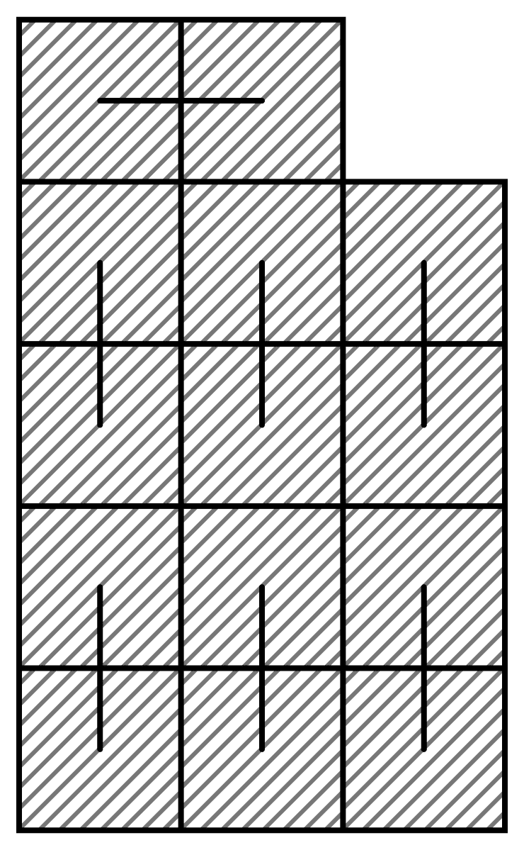
Hence, the given region can be tiled using 7 tiles of size 2 × 1.
Is the following region tileable with 2 × 1 tiles?
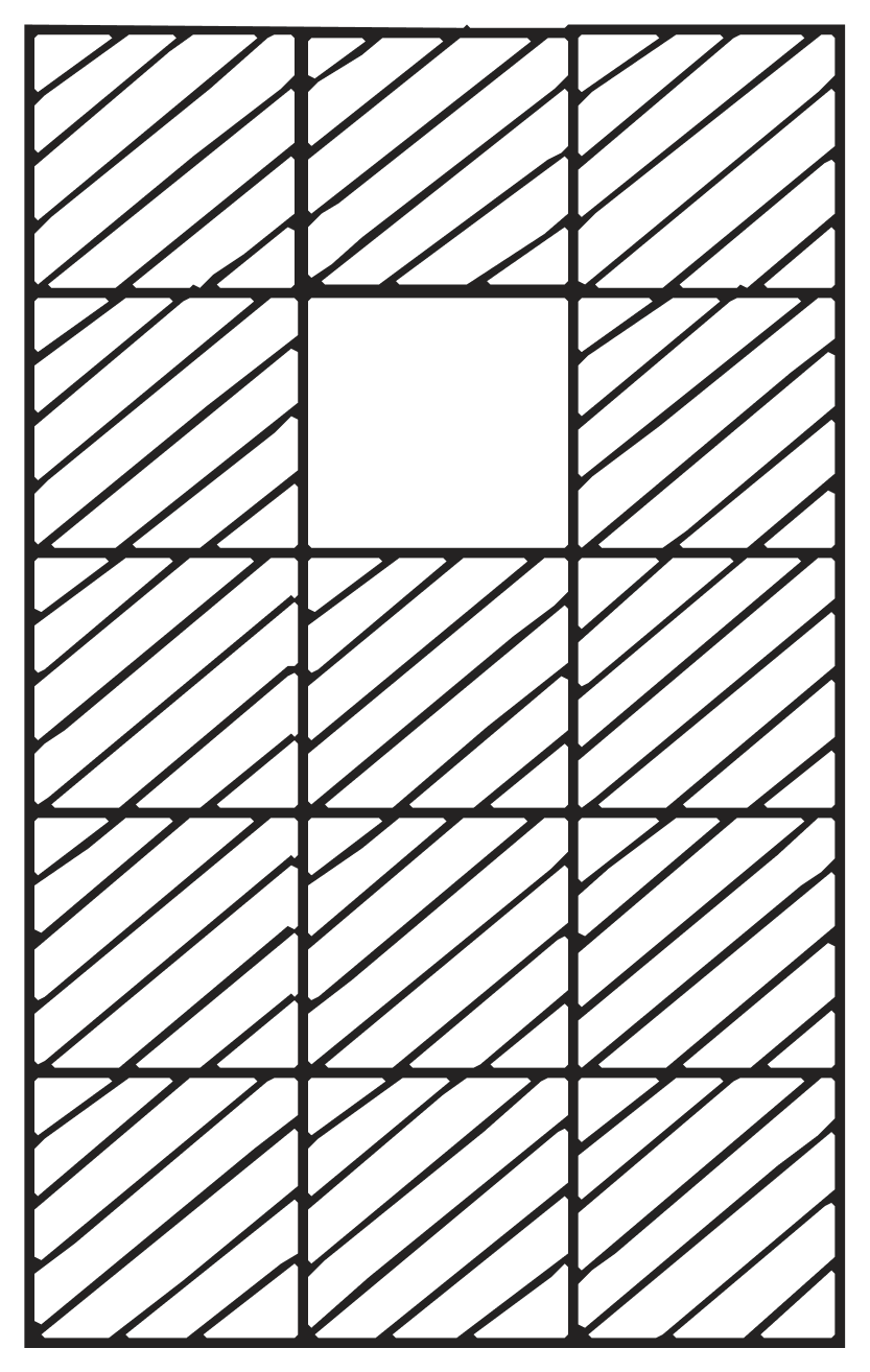
Answer
Yes, this region is tileable with 2 × 1 tiles.
Here, the square removed from the 5 × 3 grid is the middle square of the second row.
Number of unit squares in the region = 15 − 1 = 14
Number of tiles required = 14 ÷ 2 = 7
One way of tiling it is given below. (Rows are counted from the top and columns from the left.)
- A horizontal tile on the 1st and 2nd squares of row 1.
- A vertical tile on the 3rd squares of rows 1 and 2.
- A vertical tile on the 1st squares of rows 2 and 3.
- A horizontal tile on the 2nd and 3rd squares of row 3.
- A horizontal tile on the 1st and 2nd squares of row 4.
- A vertical tile on the 3rd squares of rows 4 and 5.
- A horizontal tile on the 1st and 2nd squares of row 5.
All 14 unit squares get covered, with no gaps and no overlaps.
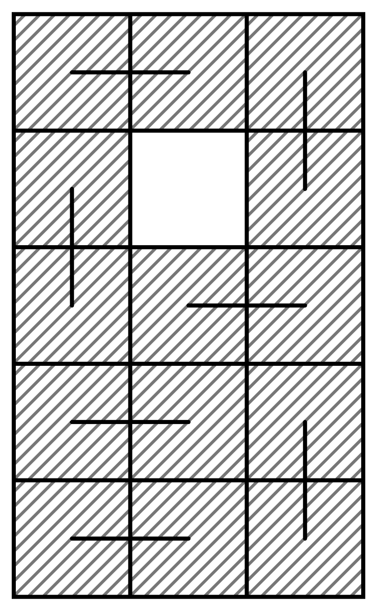
Hence, the given region can be tiled using 7 tiles of size 2 × 1.
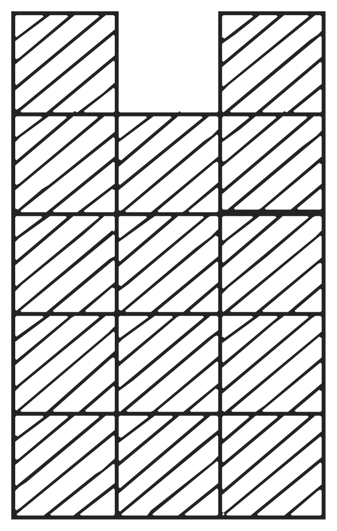
What about this one? Were you able to tile this? How can we be sure that this is not tileable?
Answer
No, the region in Fig. 6.13 is not tileable with 2 × 1 tiles.
Here, the square removed from the 5 × 3 grid is the middle square of the top row.
Number of unit squares in the region = 15 - 1 = 14
So the region has an even number of unit squares, and 7 tiles would be needed. Yet, however we try, one unit square is always left uncovered.
Having an even number of unit squares is only a necessary condition for tiling — it is not enough by itself. The reason why this particular region cannot be tiled is explained by the black-and-white colouring argument taken up in the next question.
Hence, the region in Fig. 6.13 cannot be tiled with 2 × 1 tiles.
Can you find another unit square that, when removed from a 5 × 3 grid, makes it non-tileable?
Answer
No, the region could not be tiled. We can be sure of this by colouring the grid.
Colouring the grid
Colour the 15 unit squares of the 5 × 3 grid black and white like a chessboard, so that every black square has only white neighbours and every white square has only black neighbours. Let the four corner squares be white.
Number of white squares = 8
Number of black squares = 7
Total = 8 + 7 = 15 ✓
Why the region cannot be tiled
A 2 × 1 tile, whether placed horizontally or vertically, always covers two neighbouring unit squares. Neighbouring squares have opposite colours.
⇒ Every tile covers exactly 1 white square and 1 black square.
So, if a region can be tiled using k tiles, then that region must contain exactly k white squares and k black squares, that is, equal numbers of black and white squares.
In Fig. 6.13, the square removed is the middle square of the top row, which is a black square.
White squares left = 8
Black squares left = 7 - 1 = 6
8 ≠ 6
Since the numbers of white and black squares are not equal, the region can never be tiled.
Another such unit square
Removing any black square of the 5 × 3 grid leaves 8 white squares and 6 black squares, and so makes the region non-tileable. The 7 black squares are:
| Row (from top) | Column (from left) |
|---|---|
| 1 | 2 |
| 2 | 1 |
| 2 | 3 |
| 3 | 2 |
| 4 | 1 |
| 4 | 3 |
| 5 | 2 |
For example, if the centre square of the grid (row 3, column 2) is removed, the region again has 8 white and 6 black squares, and so it cannot be tiled.
On the other hand, removing a white square — such as a corner square leaves 7 white and 7 black squares, and such regions were indeed found to be tileable.
Hence, the region of Fig. 6.13 is not tileable, and removing any one of the 7 black squares of the 5 × 3 grid makes it non-tileable.
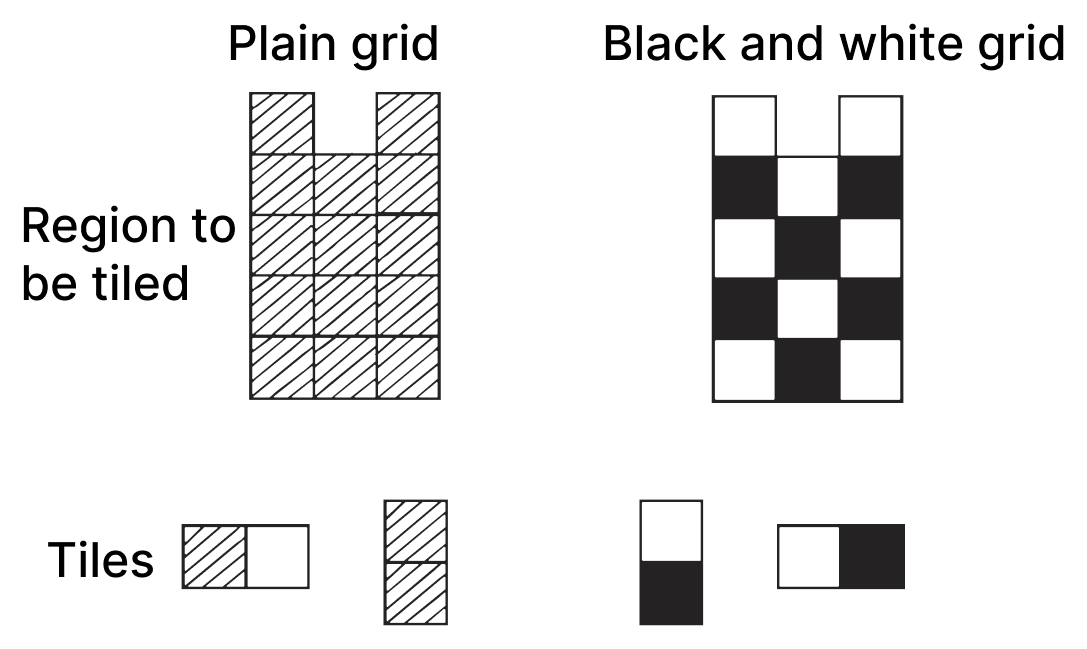
In the black-and-white region, the problem is to tile the region with the 2 × 1 black-and-white tiles so that each black square of a tile sits on a black square of the grid, and each white square sits on a white square.
If the plain grid is tileable, is the black-and-white-grid tileable?
Answer
Yes. If the plain grid is tileable, then the black-and-white grid is also tileable.
Suppose the plain region has been tiled using ordinary 2 × 1 tiles, with no gaps and no overlaps. Now colour the unit squares of the region in a chessboard pattern.
Each 2 × 1 tile covers two neighbouring unit squares. Since neighbouring squares in a chessboard colouring always have opposite colours, every tile covers exactly one black square and one white square.
Now colour each tile so that the half lying on the black square is black and the half lying on the white square is white. Thus every ordinary tile becomes a black-and-white tile placed correctly on the coloured grid.
Since only the colours of the tiles have been changed and their positions remain the same, the entire region is still covered without gaps or overlaps.
Hence, if the plain grid is tileable, the black-and-white grid is also tileable.
If the black-and-white grid is tileable, is the plain grid tileable?
Answer
Yes, it is.
Suppose the black-and-white grid has been completely tiled using the black-and-white 2 × 1 tiles, so that every black square of a tile sits on a black square of the grid and every white square of a tile sits on a white square of the grid.
Now remove the colouring from both the region and the tiles.
- Each black-and-white tile becomes an ordinary 2 × 1 tile.
- The black-and-white region becomes the plain grid.
- The tiles have not been moved at all, so they still cover every unit square exactly once, with no gaps and no overlaps.
Thus the very same arrangement of tiles is a tiling of the plain grid.
In other words, colouring only puts an extra condition on the tiles; removing that condition can never spoil a tiling.
Hence, if the black-and-white grid is tileable, then the plain grid is also tileable.
Use this idea to find another unit square that, when removed from a 5 × 3 grid, makes it non-tileable?
Answer
Colour the 5 × 3 grid black and white like a chessboard, so that neighbouring squares always get different colours. Let the four corner squares be white.
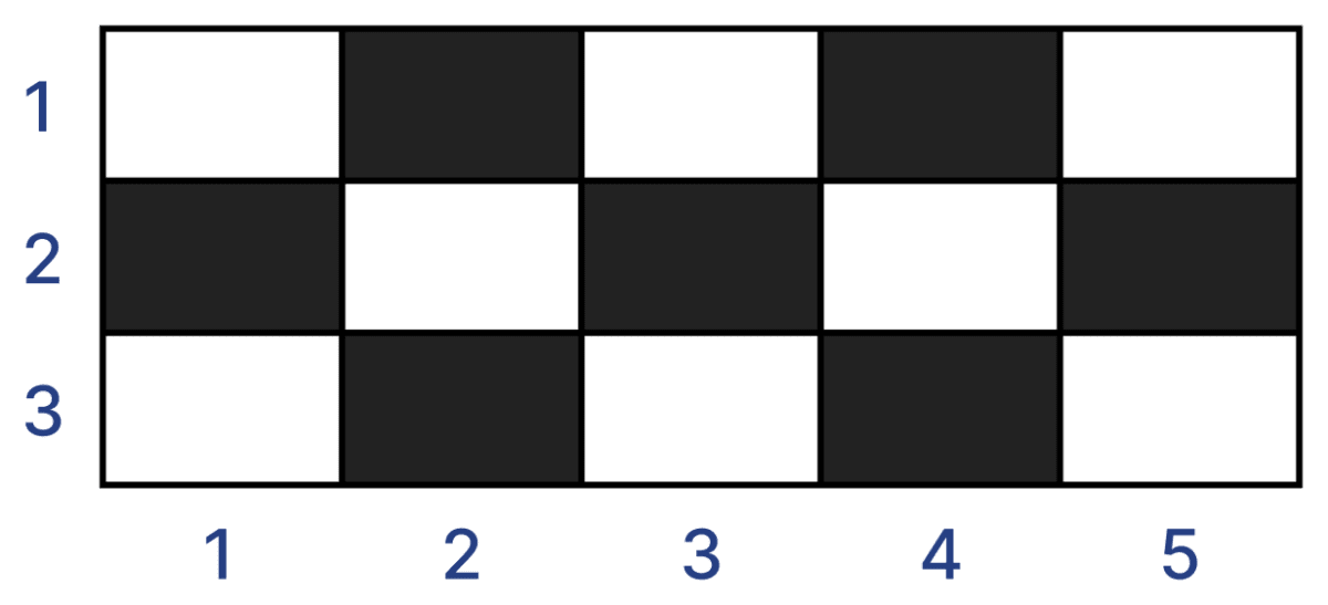
Rows 1, 3 and 5 then have 2 white and 1 black square each, while rows 2 and 4 have 1 white and 2 black squares each.
Number of white squares = 3 × 2 + 2 × 1 = 6 + 2 = 8
Number of black squares = 3 × 1 + 2 × 2 = 3 + 4 = 7
Total number of squares = 8 + 7 = 15
When one unit square is removed, 14 squares are left. Since each 2 × 1 tile covers 2 squares, we would need 14 ÷ 2 = 7 tiles, and these 7 tiles must cover 7 black and 7 white squares.
Case 1: A white square is removed.
White squares left = 8 - 1 = 7
Black squares left = 7
The counts are equal, so tiling is not ruled out.
Case 2: A black square is removed.
White squares left = 8
Black squares left = 7 - 1 = 6
Since 8 ≠ 6, tiling is impossible.
∴ Removing any black square makes the grid non-tileable. There are 7 such squares in all.
Are the following tilings possible?
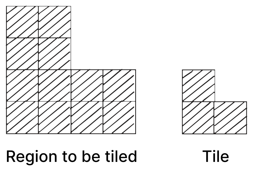
Answer
Here the region is made of a 2 × 2 block of unit squares sitting on top of a 2 × 4 block, and the tile is an L-shaped tile made of 3 unit squares.
Number of unit squares in the region = 2 × 2 + 2 × 4
= 4 + 8 = 12
Each tile covers 3 unit squares.
Number of tiles needed =
So 4 tiles are needed, and the tiling turns out to be possible.
Number the rows 1 to 4 from the top and the columns 1 to 4 from the left, and write (r, c) for the square in row r and column c. The four L-shaped tiles can be placed as follows.
- Tile 1 covers (1, 1), (1, 2), (2, 1).
- Tile 2 covers (2, 2), (3, 2), (3, 3).
- Tile 3 covers (3, 1), (4, 1), (4, 2).
- Tile 4 covers (3, 4), (4, 3), (4, 4).
Every one of the 12 unit squares is covered exactly once, and no tile sticks out of the region.
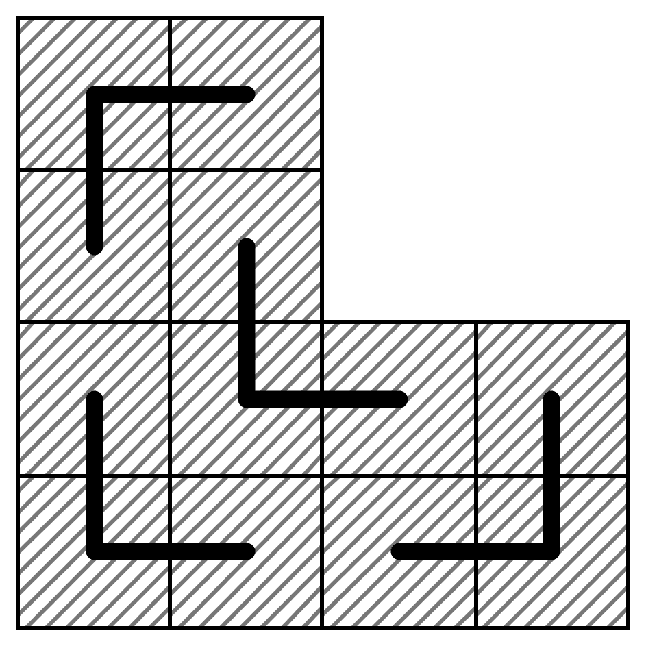
Hence, the given tiling is possible; the region can be tiled using 4 copies of the L-shaped tile.
Are the following tilings possible?
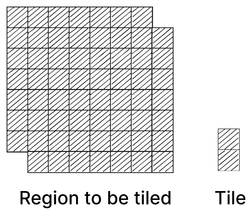
Answer
The region here is an 8 × 8 grid from which two unit squares have been removed — the square at the top right corner and the square at the bottom left corner. The tile is a 2 × 1 tile.
Number of unit squares in the region = 8 × 8 - 2
= 64 - 2 = 62
This is an even number, so counting the squares alone does not rule out a tiling; tiles would be needed. Let us therefore use the colouring idea.
Colour the 8 × 8 grid black and white like a chessboard.
Black squares in the 8 × 8 grid = 32
White squares in the 8 × 8 grid = 32
The top right corner and the bottom left corner lie at the two ends of the same diagonal, so they are of the same colour. Let both of them be black. Removing them leaves
Black squares left = 32 − 2 = 30
White squares left = 32
Now, wherever a 2 × 1 tile is placed, it always lies on two neighbouring squares, and neighbouring squares have different colours.
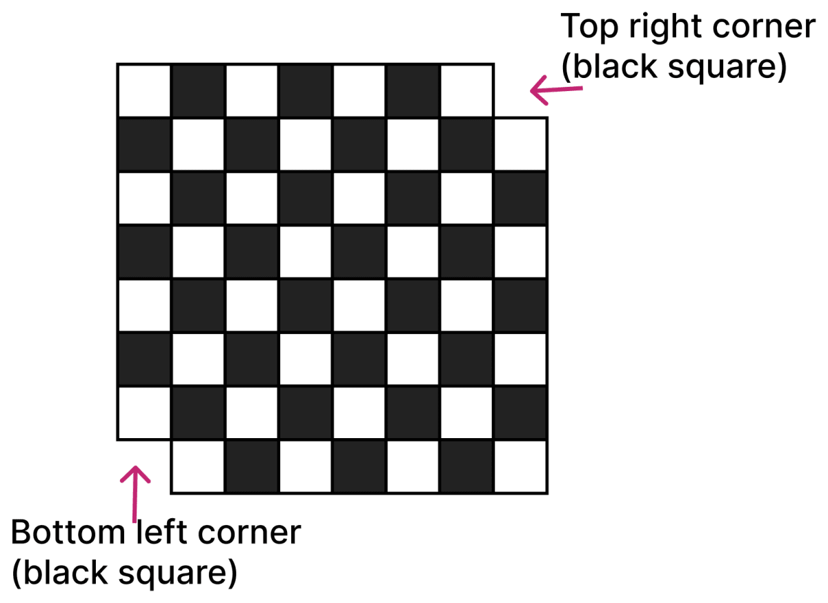
⇒ Every tile covers exactly 1 black square and 1 white square.
⇒ 31 tiles would cover 31 black squares and 31 white squares.
But the region has 30 black squares and 32 white squares, and 30 ≠ 32.
Hence, the given tiling is not possible; this region cannot be tiled with 2 × 1 tiles.
Can you think of a shape whose copies can tile the entire plane?
Answer
Yes, there are many such shapes.
Square — copies of a square tile the plane, as we see in an endless sheet of squared paper. Four squares meet at every corner and 4 × 90° = 360°, so there is no gap and no overlap.
Equilateral triangle — each angle is 60°, and six of them can be placed around a point since 6 × 60° = 360°.
Regular hexagon — each angle is 120°, and three of them fit around a point since 3 × 120° = 360°. This is the pattern seen on the front face of a beehive.

Besides these, any rectangle, any parallelogram — in fact any triangle and any quadrilateral — can also tile the plane.
A regular pentagon, however, cannot tile the plane, because each of its angles is 108° and
which is not a whole number, so copies of a regular pentagon can never fit exactly around a point.
Hence, squares, equilateral triangles and regular hexagons are examples of shapes whose copies can tile the entire plane.