
Read the excerpt from a story and answer the questions that follow:
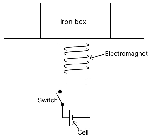
On stage, a soft iron box sits atop a hidden copper coiled platform, conductive to electricity. I summoned a man who fancied himself a modern-day Hercules onto the stage and challenged him to lift the iron box. With ease, he lifted it up. Then, with a wave of my magic wand and a hidden switch activated, I said, "I'm going to take away your strength." When I asked him to lift the box again, he struggled, unable to budge it.
(a) Explain the secret behind the magic.
(b) If you are asked to design the same magic in your science lab, give the necessary circuit diagram.
(c) Give any one device that works on the same principle.
Answer
(a) When the switch is turned on, electricity flows through the insulated copper wire beneath the platform, creating a magnetic field. This causes the coil to become an electromagnet, which then attracts the iron box.
(b) Given below is the circuit diagram
(c) Electric bell
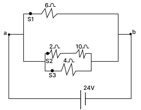
Which one of the switches, S1, S2 or S3, should be opened so that:
(a) total resistance is equal to 4 ohms.
(b) the total resistance is equal 3 ohms.
(c) the current through 4 ohms is 3⁄5th of the total current.
Answer
(a) S3
(b) S1
(c) S2
Explanation:
Let R1= 6 Ω, R2= 2 Ω, R3= 10 Ω, R4= 4 Ω
If S3 is open: then R2 and R3 are in series
then Rs and R1 are in parallel
Total resistance is 4 Ω
If S1 is open: then R2 and R3 are in series
and Rs and R4 are in parallel:
Total resistance is 3 Ω
If S2 is open: then R1 and R4 are in parallel
Total resistance is 2.4 Ω
Total current drawn in circuit
Voltage across 4 Ω is 24 V
so, current through 4 Ω is
So, the current through 4 ohms is 3⁄5th of the total current.
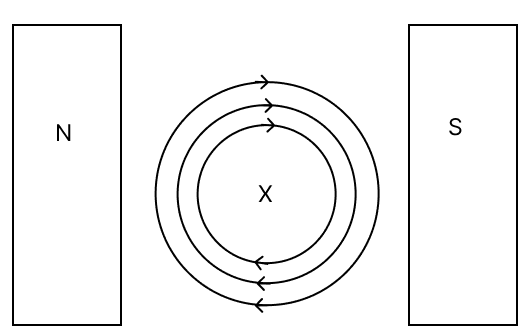
In the given diagram, X represents a conductor carrying current into the plane of the paper and kept in a magnetic field. N & S represent the poles of a magnet and concentric circles of the magnetic field produced by the conductor.
(a) State the direction of the force experienced by the conductor.
(b) Explain the cause of the above-said force.
(c) Name the law used to determine the direction of the force in the conductor.
Answer
(a) Downwards
(b) The external magnetic field runs from the north pole (left) to the south pole (right). Around the wire, concentric circles of magnetic field lines indicate the current is going into the page. According to Fleming's Left-Hand Rule, the force acts downward, toward the bottom of the page.
- Thumb indicating the force (F) direction.
- Index finger with the magnetic field (B),
- Middle finger with the current (I),
(c) Fleming’s left-hand rule.
Study the diagram and answer the following:
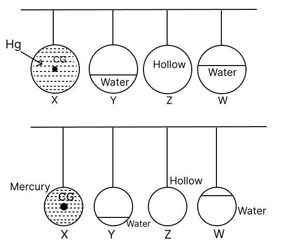
(a) Arrange the following pendulums according to their natural frequencies (use < > =).
(b) If Pendulum Z is initiated into oscillation, which pendulum among the others will exhibit the highest amplitude of vibration?
(c) Give reasons for your answer.
Answer
(a) Y < W < Z = X
(b) X
(c) As Z and X share identical natural frequencies, Z will resonate and vibrate with greater amplitude.
Explanation:
(a) Effective length = length of the thread + distance of center of gravity from point of contact of sphere.
Let, effective length of pendulum X = lx
effective length of pendulum Y = lY
effective length of pendulum Z = lZ
effective length of pendulum W = lW
For pendulum X, which is completely filled with water, and pendulum Z, which is completely hollow, the center of gravity will be at the center of the sphere due to uniform mass distribution.
For pendulum W, where water fills more than half of the sphere, the center of gravity will be below the geometric center of the sphere. Conversely, for pendulum Y, where water fills less than half of the sphere, the center of gravity will be even lower than that of pendulum W (or, "further below the geometric center").
Here, lY > lW > lZ = lX
"Greater the effective length, smaller the frequency."
Y < W < Z = X
(b) If pendulum Z is set into oscillation, pendulum X will exhibit the highest amplitude of vibration due to resonance
(c) When the natural frequency of Z matches the natural frequency of X, X will vibrate with a higher amplitude due to resonance.
In the physics laboratory, various blocks of materials labelled A and B, each with masses ranging from 10 grams to 50 grams, are utilised to determine their respective heat capacities. Subsequently, a graph is plotted to depict the relationship between the heat capacity and the mass of the materials, as shown.
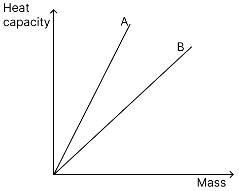
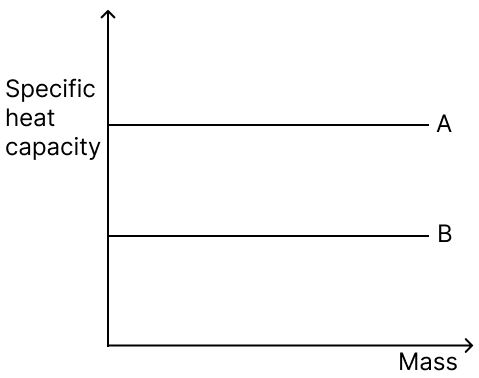
(a) Plot a graph illustrating the relationship between the mass and specific heat capacity of materials A and B.
(b) Which material is a relatively better conductor?
Answer
(a)
(b) B
Explanation:
Generally, materials with lower specific heat capacity heat up more quickly when thermal energy is applied. Hence, Material B, with the lower specific heat capacity, would be a better thermal conductor.
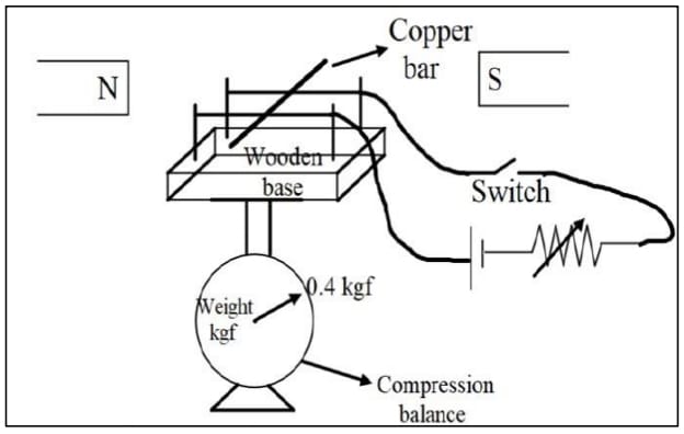
The above circuit diagram illustrates a copper bar placed on two copper wires stretched over a wooden base placed between two poles of magnets. This entire setup is placed on a compression balance, which shows a weight of 0.4 kgf.
(a) What will be the observation of the compression balance when we close the switch?
(b) How will this observation change, when we increase the current in the circuit?
(c) Name the rule used to come to the conclusion in (a).
Answer
(a) The reading on the compression balance will increase.
(b) The reading on the compression balance will increase.
(c) Fleming’s left-hand rule.
Explanation:
When the switch is closed, current flows through the copper bar in a magnetic field. This causes a Lorentz force (also called the magnetic force) to act on the conductor. This force is perpendicular to both the direction of current and the magnetic field. Due to this, the copper bar experiences a downward force, causing the compression balance reading to increase.
Bandish and Parag, on a trek to Sandakpu, halted at a tea house in Tumbling. The picture above shows the entrance door of the tea house. They saw the tumbrel filled with water hanging from top rigid support passing through the door. On enquiring about the tumbrel, the owner of the tea house, he said that it acts as a pullback (door closure) after opening and releasing the door.
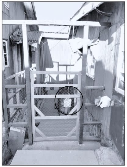
(a) Explain how the tumbrel helps to close the door on its own.
(b) Name the principle involved.
Answer
(a) Initially, the center of gravity of the tumbrel is vertically below the fixed support, so the torque on the door is zero as the torque arm is zero.
But when we push the door to open it, the tumbrel moves away and now there is some torque arm which acts on the door to bring it back to its original position.
(b) Principle of moments.
A convex lens of power +5 D has an object placed at a distance of 50 cm in front of the lens.
(a) State the nature of the image formed.
(b) What is the definite distance, towards or away from the lens, the object should move so that the image is not seen?
Answer
Given, power (P) = +5 D
Object distance = u = -50 cm
Let, image distance = v
Focal length = f =
Focal length = f = +20 cm
Here, object is placed beyond 2F (twice the focal length) of a convex lens, the image will be formed between F and 2F on the opposite side of the lens. Hence, Image is real and diminished.
(b) The object is at 50 cm. If we move the object 30 cm towards the lens, it will be at the focal point (20 cm), so the rays will emerge parallel, and a real image will not be formed.
So, the new position of object = 50 - 30 = 20 cm
∴ The object should be moved 30 cm towards the lens.
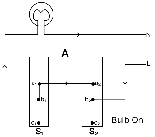
The diagram below shows a bulb connected by dual control switches. Observe the diagrams and answer the questions that follow.
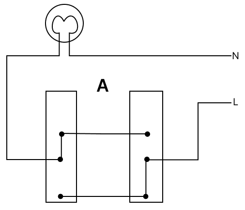
(a) Which of the above circuits will be able to switch ON or switch OFF the bulb using both switches?
(b) At present, in which circuit is the bulb glowing?
(c) If we interchange the L and N wires in circuit B, will the circuit work?
Answer
(a) Both circuits will be able to switch ON and switch OFF the bulb using both switches.
(b) Circuit B
(c) Yes, the circuit will function.
Explanation:
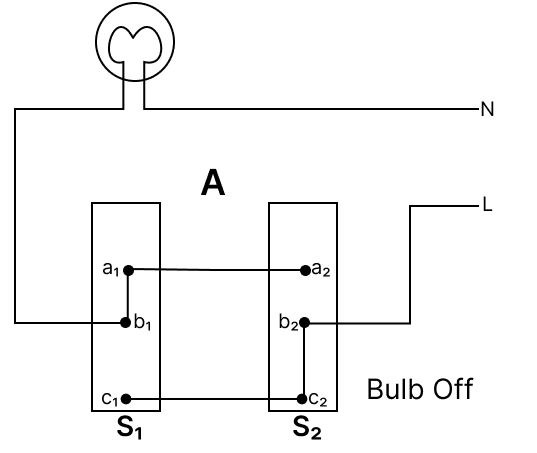
(a) Circuit A : Figure illustrate the dual control switch in an electric circuit. Two such switches S1 and S2 are used. The figure A shows the 'off' position of the bulb.
Figure A
The bulb can now be switched 'on' independently by either the switch S1 or the switch S2.
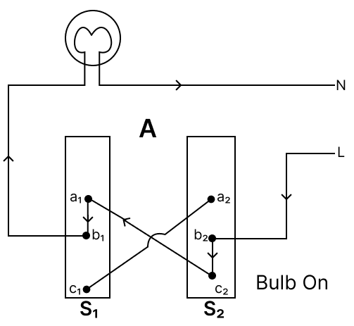
If the switch S1 is operated, the connection 'b1a1' is changed to 'b1c1', which completes the circuit and the bulb lights up and by reversing the process it can turn off.
Figure A1
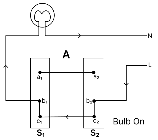
Similarly, If the switch S2 is operated from the position shown in figure A the connection 'b2c2' changes to 'b2a2', which again completes the circuit and the bulb lights up and by reversing the process it can turn off.
Figure A2
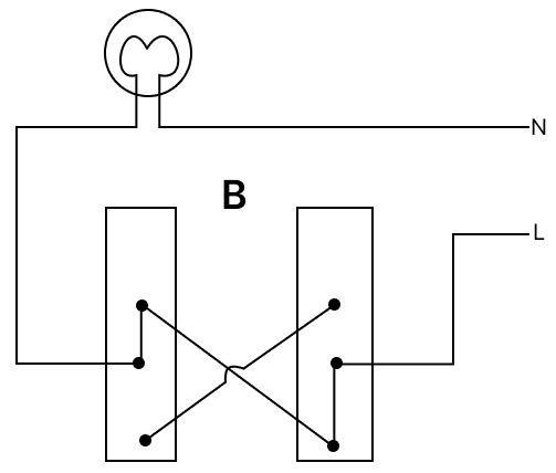
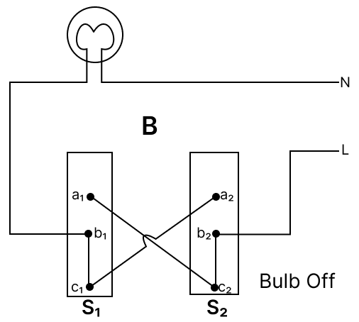
Circuit B : This figure also illustrate the dual control switch in an electric circuit. Two such switches S1 and S2 are used, and the Figure B shows the 'on' position of the bulb.
Figure B
The bulb can now be turned 'off' independently by either the switch S1 or the switch S2.
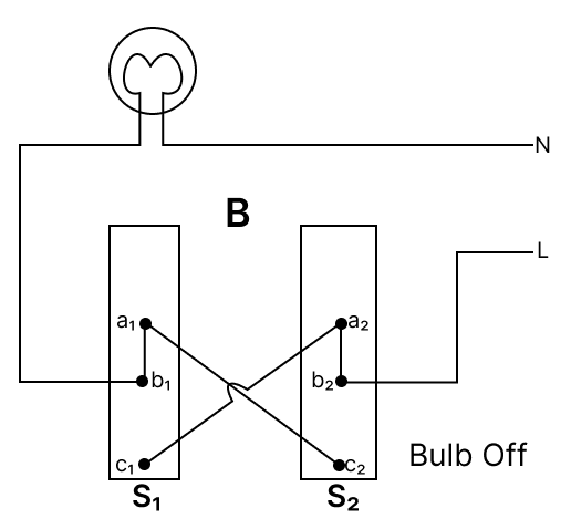
If the switch S1 is operated, the connection changes from 'b1a1' to 'b1c1', which breaks the circuit and turns the bulb off. Reversing the process restores the connection, turning the bulb on.
Figure B1
Similarly, when the switch S2 is operated from the position shown in Figure B, the connection changes from 'b2c2' to 'b2a2', breaking the circuit and turning the bulb off. Reversing the process reconnects the circuit, allowing the bulb to turn on.
Figure B2
(b) In circuit A current flows from:
live wire ⟶ b2 ⟶ c2 ⟶ c1
Hence, it does not complete the circuit.
In circuit B current flows from:
live wire ⟶ b2 ⟶ c2 ⟶ a1 ⟶ b1 ⟶ bulb ⟶ Neutral wire
Hence, it completes the circuit.
(c) A standard incandescent light bulb is NOT dependent on the polarity of the connection for its basic operation (lighting up). So by changing L and N wires, the circuit will function.
Observe the electric circuit below and answer the questions that follow.
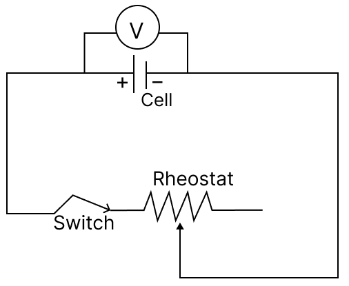
(a) If we increase the current in the above circuit using a rheostat, will the reading of the voltmeter decrease or increase?
(b) Give a reason for your answer in ‘a’.
(c) The present reading of the voltmeter is 2 V, and the current in the circuit is 0.8 A. Calculate the potential drop when the current in the circuit becomes 1 A. Given E = 3 V.
Answer
(a) Decrease.
(b) This is because the voltmeter shows terminal voltage. Increase in current increases potential drop which decreases terminal voltage.
(c) Potential drop = EMF - Terminal voltage
Potential drop = 3 - 2 = 1 V
Let internal resistance = r
New current = 1 A
New potential drop = 1 × 1.25 = 1.25 V
Pavel took an earthen pot which was filled with water up to its brim. The earthen pot was conical in shape and kept with its apex in downward direction.
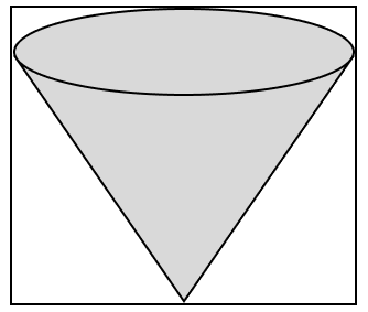
(a) If the vertical height of the earthen pot is 12 cm, where does its centre of gravity lie?
(b) Pavel poured out all the water from the pot. How will its centre of gravity shift towards the open end or towards its apex?
(c) Pavel wanted to grow a plant in the given pot. So, he filled it completely again with some soil. What will be the new position of its centre of gravity?
Answer
(a) Centre of gravity of solid cone = cm from the base
= cm from the base
= 3 cm from the base
= 12 - 3 = 9 cm from the apex
∴ Centre of gravity lies 3 cm from the base or 9 cm from the apex.
(b) Centre of gravity of hollow cone = cm from the base
= cm from the base
= 4 cm from the base
∴ Centre of gravity shifts towards the apex.
(c) Since the mass distribution is uniform and the body behaves like a solid cone, the center of mass will remain at its original position i.e., 3 cm from the base or 9 cm from the apex.
The mass of the block P is 5 kg. It is to be moved along an inclined plane AC of length 8 m, which makes an angle of 30° with the horizontal. A force of 50 N is applied on the block to move it through the inclined plane AC, as shown in the diagram.
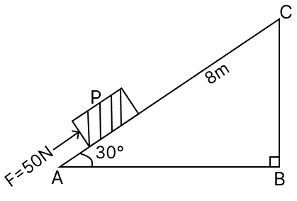
(a) What is the work done by the force along the inclined plane?
(b) Find the gain in potential energy of block P if it is directly lifted to C from the ground. (g = 10 ms-2)
(c) We know that potential energy is gained due to the work done on the body against gravity. Then, in this case, why is the work done on the block and the increase in the potential energy of the block different?
Answer
(a) W = F x S = 50 x 8 = 400 J
(b) Given, ∠ A = 30 °, AC = 8 cm
in △ABC,
Potential energy gained = mgh = 5 x 10 x 4 = 200 J
(c) This is because while pushing the block along the inclined plane, some energy is wasted to overcome the friction between the block and the inclined plane.
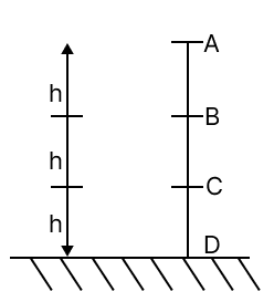
A ball of mass m is dropped freely from point A. It is given that AB = BC = CD = h. If the acceleration due to gravity at the given place is g, then what will be its
(a) potential energy at point A?
(b) kinetic energy at point C?
Answer
(a) Height of point A = 3h
So, potential energy PA = mg x 3h = 3mgh
(b) At point A, initial velocity = u = 0
At point C, final velocity = v
So, from third equation of motion:
v2 = u2 + 2g x 2h = u2 + 4gh
v2 = 4gh ...............(i)
Kinetic energy at C point, KC =
KC = 2mgh
In a science exhibition, boys of a Secondary school made two types of periscopes. In one of the periscopes, ordinary glass was used as the reflecting material, while in the other, a prism was used. When Anushka put her eyes on the eyepiece of the periscope, she saw that the image formed in one of the periscopes was quite bright, while in the other, it was a little blurred.
(a) In which of the two periscopes, mirror or prism, Anushka saw the image brighter?
(b) Why is one of the images brighter than the other?
Answer
(a) Image is brighter in the prism periscope.
(b) This is due to the phenomenon of total internal reflection of light. During TIR, there is no absorption of light energy by the prism.
ABC is a glass block whose two sides, AB and BC, are at right angles to each other. A ray of light is incident on the surface AB, as shown in the diagram, and suffers total internal reflection before falling on the surface BC. Finally, the light ray emerges out along the surface BC.
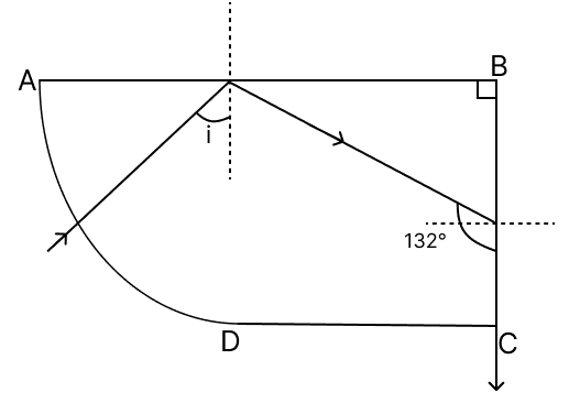
(a) What is the angle of incidence at the surface AB?
(b) What is the critical angle for the glass block BC?
(c) What would happen to the critical angle if the temperature of the glass block is increased?
Answer
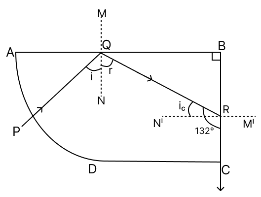
(a)
∠r = ∠NQR = ∠QRB (alternate angle)
∠QRC + ∠QRB = 180°
∠QRB = 180° - ∠QRC
∠r = 180° − 132° = 48°
∠i = ∠r [∵ Law of reflection]
∴ ∠i = 48°
(b) ∠ic = ∠QRN' = 132° − 90° = 42°
(c) On increasing the temperature of a medium, its refractive index decreases, therefore the critical angle increases with the increase in temperature.
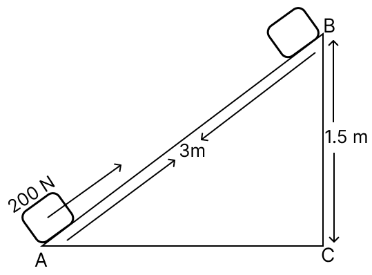
A block of mass 30 kg is pulled up a slope (diagram below) with a constant speed by applying a force of 200 N parallel to the slope. A and B are the initial and final positions of the block. Calculate the force of friction offered by the surface AB.
Answer
Given, mass of block (m) = 30 kg
Force applied (F) = 200 N
Work done along AB :
WAB = F x SAB
= 200 x 3 = 600 N m = 600 J
Work done along CB:
WCB = m x g x SCB
= 30 x 10 x 1.5 = 450 J
Let, friction force = f
Work done by friction WF =f x 3
Hence, the force of friction offered by the surface AB is 50 N.
A roller with a diameter of 0.2 m is raised over a pavement AB by applying forces F1 and F2, as shown in the diagram.
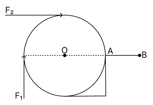
If the magnitude of both forces is 20 N, then compare the magnitudes of the torques produced by the two forces.
Answer
Anticlockwise torque is taken as positive, while clockwise torque is taken as negative according to the standard sign convention used in rotational motion analysis.
Here, for force F1, the axis of rotation will pass through point A.
Perpendicular distance = Diameter of roller = 0.2 m
So,
Clockwise torque due to F1 = -20 x 0.2 = -4 N m
For force F2, the axis of rotation will pass through point O.
Perpendicular distance = Radius of roller = = 0.1 m
So,
Clockwise torque due to F2 = -20 x 0.1 = -2 N m
Ratio of torques =
Ratio of torques = F1 : F2 = 2 : 1