
The number of electrons in 1 C charge is :
- 6.25 x 10¹⁸
- 6.25 x 10¹⁹
- 6.25 x 1025
- 1.6 x 10⁻¹⁹
Answer
6.25 x 10¹⁸
Reason — The number of electrons in 1 C charge is 6.25 x 10¹⁸.
The current in a circuit is measured by ............... by connecting it in ...............
- voltmeter, series
- voltmeter, parallel
- ammeter, series
- ammeter, parallel
Answer
ammeter, series
Reason — By connecting the ammeter in series, the entire current flowing through the circuit also flows through the ammeter, allowing it to measure the current accurately.
If n electrons pass through a cross-section of a conductor in time t, then current in conductor is :
- I =
- I =
- I =
- I =
Answer
I =
Reason — If n electrons pass through a cross-section of a conductor in time t, then current in conductor is I =
If W joule of work is done in bringing a test charge Q coulomb from infinity to the point P, then electric potential V at point P is :
- V = WQ
- V = Q/W
- V = W/Q
- none of the above
Answer
V = W/Q
Reason — If W joule of work is done in bringing a test charge Q coulomb from infinity to the point P, then electric potential V at point P is V = W/Q .
The potential difference between two points in an electric circuit is measured by a ............... which is connected in ............... with the circuit.
- voltmeter, series
- voltmeter, parallel
- ammeter, series
- ammeter, parallel
Answer
voltmeter, parallel
Reason — Connecting the voltmeter in parallel ensures that it measures the potential difference accurately because it doesn't affect the current flow in the circuit.
According to Ohm's law :
- I ∝ V
- V/I = constant
- V = IR
- All of the above
Answer
All of the above
Reason — According to Ohm's Law : V = IR
Hence, I ∝ V and V/I = constant
Hence, all are correct.
1 ohm is equal to:
- 1 volt
- Volt x ampere
- volt/ampere
- all of the above
Answer
volt/ampere
Reason — 1 ohm = volt/ampere
The unit of conductance is :
- volt
- ohm
- ohm-1
- ampere
Answer
ohm-1
Reason — The unit of conductance is ohm-1.
Out of the following, non-ohmic resistor is :
- nichrome
- copper sulphate solution with copper electrodes and dil sulphuric acid.
- solar cell
- silver
Answer
solar cell
Reason — Nichrome, Copper sulphate solution with copper electrodes and dil sulphuric acid, Silver, all the three follow Ohm's Law i.e., V = IR, hence they are ohmic conductors whereas a solar cell is a non-ohmic conductor.
The resistance of a conductor depends on :
- the temperature of the conductor
- the thickness of the conductor
- the length of the conductor
- all of the above
Answer
all of the above
Reason — The three factors on which the resistance of wire depends are —
- Dependence on length of the wire — the resistance of a wire is directly proportional to the length of the wire.
R ∝ l - Dependence on the thickness of the wire — the resistance of a wire is inversely proportional to it's area of cross section (a) normal to the direction of flow of current.
R ∝ - Dependence on the temperature of the wire — the resistance of conductor increases with an increase in it's temperature.
The specific resistance of a rod of aluminium as compared to that of a thin wire of aluminium is :
- Less
- More
- Same
- Depends upon the area of cross section and length of both.
Answer
Same
Reason — Specific resistance of an object is an intrinsic property which is independent of it's dimensions but does depend upon nature of material and temperature. Since both rod and thin wire are of same material i.e., aluminium so both will have same specific resistance.
If the length l of wire is increased to 3l by stretching, its resistance R increases to ...............
- 3R
- 4R
- 6R
- 9R
Answer
9R
Reason — When the wire is stretched to thrice it's length, it's area of cross section becomes 1/3 and it's length becomes 3l.
Let, a be the area of initial cross section and ρ be the specific resistance of the material of wire.
Then,
- length = l,
- Resistance = R Ω,
- New length = 3l,
- New area =
From relation
R = ρ = ρ
Initial resistance (R1) = R = ρ [Equation 1]
New resistance (Rn) = ρ = ρ [Equation 2]
On dividing eqn (ii) by (i), we get,
Hence, the new resistance = 9R.
Which of the following is an ohmic resistor?
- LED
- junction diode
- filament of a bulb
- nichrome wire
Answer
nichrome wire
Reason — The conductors which obey the Ohm's law are called the ohmic resistors or linear resistances. A Nichrome wire obeys Ohm's law hence it is an ohmic resistor.
For which of the following substances, resistance decreases with increase in temperature :
- copper
- mercury
- carbon
- platinum
Answer
carbon
Reason — Resistance decreases with increase in temperature for carbon.
Standard resistors are made of :
- Copper
- Aluminium
- Constantan
- Carbon
Answer
Constantan
Reason — Standard resistors are made of constantan as it has high specific resistance and the effect of change in temperature on its resistance is negligible.
The properties for which nichrome wire is used in heating appliances is/are :
- Specific resistance is high
- Resistance decreases with an increase in temperature
- Resistance increases with an increase in temperature
- Both its high resistivity and its increase in resistance with rise in temperature
Answer
Both its high resistivity and its increase in resistance with rise in temperature
Reason — Nichrome wire is commonly used in heating appliances due to its following properties:
- Specific resistance is high — Nichrome wire has a relatively high specific resistance, which means it resists the flow of electric current efficiently, resulting in heating when current passes through it.
- Resistance increases with an increase in temperature — This property is desirable for heating elements because it helps maintain a consistent level of heating even as the temperature rises.
A super conductor is a substance of :
- infinite conductance
- infinite resistance
- zero resistance
- both zero resistance and infinite conductance
Answer
both zero resistance and infinite conductance
Reason — A superconductor exhibits both infinite conductance and zero resistance, allowing electric current to flow through it without any loss of energy due to resistance.
Write an expression connecting the resistance of a wire and specific resistance of its material. State the meaning of the symbols used.
Answer
The expression is —
R = ρ
where
- R = resistance of wire
- ρ = specific resistance of the material of wire
- l = length of wire
- a = area of cross section of wire
State the order of specific resistance of (i) a metal, (ii) a semiconductor, and (iii) an insulator.
Answer
The order of specific resistance is as follows:
- The specific resistance is very low for metals, because it allows most of current to pass through it.
- The specific resistance is low for semiconductor.
- The specific resistance is very high for insulators, as the current won't pass through it.
Name a substance of which the specific resistance remains almost unchanged by the increase in temperature.
Answer
The substance whose specific resistance remains almost unchanged with increase in temperature is manganin.
Name the material used for (i) filament of an electric bulb, and (ii) heating element of a room heater.
Answer
(i) The material used for the filament of an electric bulb is a tungsten wire because it has a high melting point.
(ii) The material used for the heating element of a room heater is nichrome because the specific resistance of nichrome is high and it's resistance increases to a great extent with the increase in temperature.
A substance has zero resistance below 1 K. What is such a substance called ?
Answer
A substance of zero resistance (or infinite conductance) at a very low temperature is called a superconductor.
Define the term current and state its S.I. unit.
Answer
Current is defined as the rate of flow of charge. The S.I. unit of charge is coulomb and therefore current is measured in coulomb per second which has been given the name ampere (A).
Define the term electric potential. State its S.I. unit.
Answer
The electric potential at a point is defined as the amount of work done per unit charge in bringing a positive test charge from infinity to that point. The S.I. unit of electric potential is volt.
How is the electric potential difference between two points defined? State its S.I. unit.
Answer
The potential difference (p.d.) between two points is equal to the work done per unit charge in moving a positive test charge from one point to the other. It's S.I. unit is volt. It is a scalar quantity.
Explain the statement 'the potential difference between two points is 1 volt'.
Answer
The potential difference between two points is said to be 1 volt if the work done in moving 1 coulomb charge from one point to other is 1 joule i.e.,
1 volt = = 1 J C-1
(a) State whether the current is a scalar or vector? What does the direction of current convey?
(b) State whether the potential is a scalar or vector? What does the positive and negative sign of potential convey?
Answer
(a) Current is a scalar quantity.
By stating the direction of current in a conductor we mean that the direction of motion of electrons is opposite to it.
(b) Potential is a scalar quantity.
When the potential is positive at a point in the vicinity of a positive charge since work has to be done on the positive test charge against the repulsive force due to the positive charge in bringing it from infinity, while it is negative at a point in the vicinity of a negative charge since the attractive force on test charge due to the negative charge does work by itself.
Define the term resistance. State its S.I. unit.
Answer
The obstruction offered to the flow of current by the conductor (or wire) is called it's resistance.
The S.I. unit of resistance is Ohm.
(a) Name the particles which are responsible for the flow of current in a metallic wire.
(b) Explain the flow of current in a metallic wire on the basis of movement of the particles named by you above in part (a).
(c) What is the cause of resistance offered by the metallic wire in the flow of current through it?
Answer
(a) The particles which are responsible for the flow of current in a metallic wire are free electrons.
(b) In a metallic wire, the moving charges are the free electrons which constitute the current.
If n electrons pass through the cross section of a conductor in time t, then total charge passed through the conductor is given as
Q (charge) = n × e
and the current in conductor is
(c) When the ends of a metal wire are connected to a cell, the electrons inside it experience a force in direction from the end at negative potential to positive, due to which they began to move as shown in the diagram below.
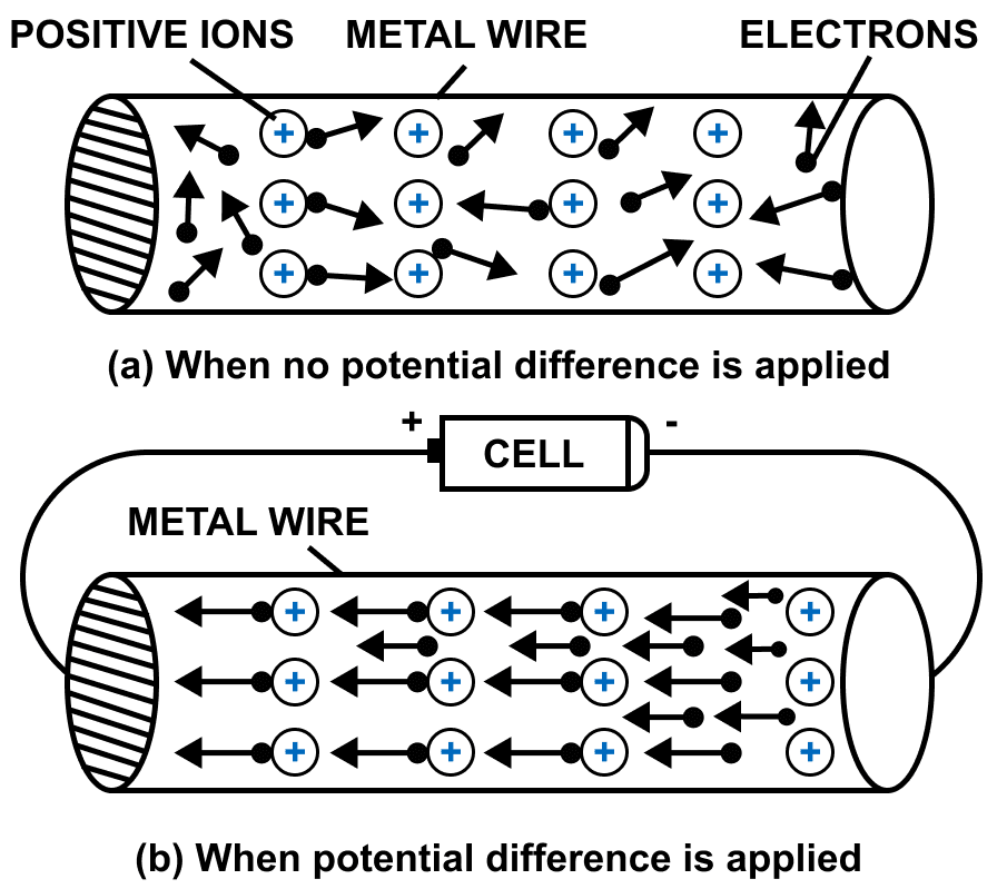
Due to force, their speed increases but during the movement they collide with the fixed positive ions and loose some of their kinetic energy due to which their speed decreases. This lost energy heats up the wire.
After the collision, they are again accelerated towards the positive potential due to the existing potential difference so their speeds again increases and then again in collision with the positive ions, their speed decreases. This process continues. As a result, the electrons do not move in bulk with a continuously increasing speed, but their is a drift of electrons towards the positive terminal. Thus, a metal wire offers some resistance to the flow of electrons through it.
(a) Name and state the law which relates the potential difference and current in a conductor.
(b) What is the necessary condition for a conductor to obey the law named above in part (a)?
Answer
(a) The law which relates the potential difference and current in a conductor is known as Ohm's law.
Ohm's law states that the current flowing through the conductor is directly proportional to the potential difference across it's ends provided that the physical conditions and the temperature of the conductor remain constant.
(b) The necessary condition for a conductor to obey Ohm's law is that the physical conditions and the temperature should remain constant.
Give two differences between an ohmic and non-ohmic resistor.
Answer
| Ohmic resistor | Non-ohmic resistor |
|---|---|
| It obeys the Ohm's law i.e., is constant for all values of V and I. | It does not obey the Ohm's law i.e., is not same for all values of V and I. |
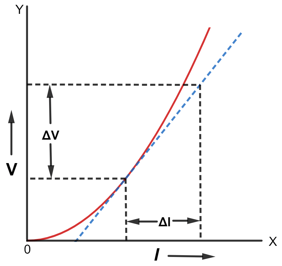
| The graph for potential difference V versus current I is a straight line passing through the origin. | The graph for potential difference V versus current I is not a straight line, but is a curve which may not pass through the origin. |
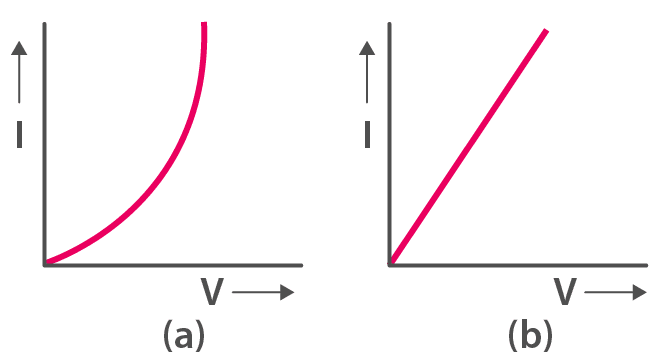
Below figure shows the I-V curves for two resistors. Identify the ohmic and non-ohmic resistors. Give a reason for your answer.
Answer
Graph (a) is non-ohmic resistor and
Graph (b) is ohmic resistor.
The I-V graph for (b) is a straight line or linear while for (a), the graph is a curve.
How does the resistance of a wire depend on its length ? Give a reason for your answer.
Answer
Resistance of a wire is directly proportional to the length of the wire.
R ∝ l
In a long conductor, the number of collisions of free electrons with the positive ions will be more as compared to a shorter one. Therefore, a longer conductor offers more resistance. Hence, the resistance of a conductor is directly proportional to the length of the wire.
How does the resistance of a metallic wire depend on its temperature? Explain with reason.
Answer
With the increase in temperature of a conductor, the random motion of electrons increases. As a result, the number of collisions of electrons with the positive ions increase. Hence, the resistance of a conductor increases with an increase in it's temperature.
Two wires, one of copper and the other of iron, are of the same length and same radius. Which will have more resistance? Give reason.
Answer
The iron wire will have more resistance.
Iron wire has more resistance as compared to copper because specific resistance of iron is more than that of copper.
Name three factors on which resistance of a given wire depends and state how it is affected by the factors stated by you?
Answer
The three factors on which the resistance of wire depends are —
- Dependence on length of the wire — the resistance of a wire is directly proportional to the length of the wire.
R ∝ l - Dependence on the thickness of the wire — the resistance of a wire is inversely proportional to it's area of cross section (a) normal to the direction of flow of current.
R ∝ - Dependence on the temperature of the wire — the resistance of conductor increases with an increase in it's temperature.
Define the term specific resistance and state its S.I. unit.
Answer
Specific resistance of a material is the resistance of a wire of that material of unit length and unit area of cross section.
The S.I. unit of specific resistance is ohm × metre or (Ω m)
(a) Name two factors on which the specific resistance of a wire depends?
(b) Two wires A and B are made of copper. The wire A is long and thin, while the wire B is short and thick. Which will have more specific resistance?
Answer
(a) Two factors on which the specific resistance of a wire depends are —
- Material of the substance — It is a characteristic property of the substance. It is different for different substances.
- Temperature of the substance — It increases with the increase in temperature for metals, but it decreases with the increase in temperature for the semiconductor.
(b) Both the wires will have the same specific resistance because the specific resistance is a characteristic property of the material and as both the wires are of copper hence both will have same specific resistance.
How does the specific resistance of a semi-conductor change with the increase in temperature?
Answer
The specific resistance of a semi-conductor decreases with the increase in temperature.
How does (a) resistance, and (b) specific resistance of a wire depend on its (i) length, and (ii) radius?
Answer
(a) Dependency of resistance of a wire is as follows:
- Resistance of a wire is directly proportional to length of the wire.
- Resistance of a wire is inversely proportional to the square of radius of the wire.
(b) Dependency of specific resistance of a wire is as follows:
- Specific resistance of a wire does not depend on length of the wire as it is a characteristic property of the material of wire.
- Specific resistance of a wire does not depend on radius of the wire as it is a characteristic property of the material of wire.
(a) Name the material used for making connection wires. Give a reason for your answer.
(b) Why should a connection wire be thick?
Answer
(a) Copper or aluminium materials are used for making connection wires because their specific resistance is very low and hence they possess least possible resistance.
Due to low (or negligible) resistance of connection wires, the current in circuit remains unaffected, and the loss of energy due to heating is prevented. Hence, they are made of materials such as copper or aluminium, whose specific resistance is very small.
(b) The connection wires are made thick so that their resistance becomes low.
Name a material which is used for making a standard resistor. Give a reason for your answer.
Answer
Standard resistors are made of magnanin, constantan etc. for which the specific resistance is high and the effect of change in temperature on their resistance is negligible.
Name the material used for making a fuse wire. Give a reason.
Answer
The material used for making fuse wire is an alloy of lead and tin because it's melting point is low and it's specific resistance is more than that of copper or aluminium so that the resistance of a short and thin fuse wire is more than that of the connecting wire. It permits current upto it's safe limit to pass through it, but an excessive current melts it so that it blows off and the circuit is broken.
What is a superconductor ? Give one example of it.
Answer
A superconductor is a substance of zero resistance (or infinite conductance) at a very low temperature.
Example — Mercury below 4.2 K, lead below 7.25 K and niobium below 9.2 K
Resistances of these substances decrease tremendously with the decrease in temperature and become almost zero in the low temperature range near absolute zero. Zero resistance of a superconductor means it's infinite conductivity (i.e., once a current starts flowing in a superconductor, it persists even when there is no potential across it).
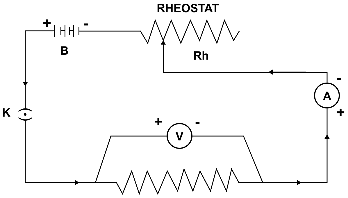
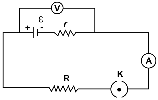
State Ohm's law and draw a neat labelled circuit diagram containing a battery, a key, a voltmeter, an ammeter, a rheostat and an unknown resistance to verify it.
Answer
According to Ohm's law, the current flowing in a conductor is directly proportional to the potential difference applied across it's ends provided that the physical conditions and the temperature of the conductor remain constant.
If a current I flows in a conductor when the potential difference across it's ends is V and R is the resistance, then according to Ohm's law V = IR
Below circuit diagram shows the setup for verifying Ohm's law:
(a) Draw a V-I graph for a conductor obeying Ohm's law.
(b) What does the slope of V-I graph for a conductor represent?
Answer
(a) V-I graph for a conductor obeying Ohm's law is shown below:
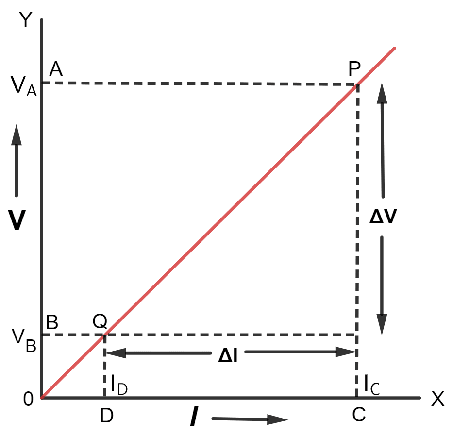
(b) Slope of V-I graph for a conductor represents resistance.
Draw an I-V graph for a linear resistor. What does its slope represent?
Answer
I-V graph for a linear resistor
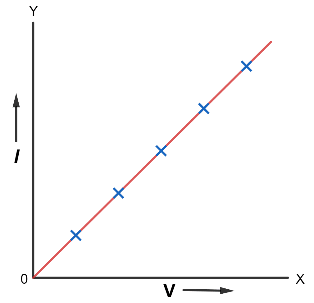
Slope of I-V graph — The slope of I-V graph is which is the reciprocal of resistance of the conductor i.e.,
Slope = =
What is an ohmic resistor? Give one example of an ohmic resistor. Draw a graph to show its current–voltage relationship. How is the resistance of the resistor determined from this graph?
Answer
The conductors which obey the Ohm's law are called the ohmic resistors or linear resistances. Examples are all metallic conductors (such as Silver, Aluminium, Copper, Iron etc.)
Current–Voltage relationship of an ohmic resistor is shown in the below graph:
Resistance is determined in the form of slope from the graph.
What are non-ohmic resistors? Give one example and draw a graph to show it's current-voltage relationship.
Answer
The conductors which do not obey the Ohm's law are known as the non-ohmic resistors (or non-linear resistances). Examples — LED, solar cell, junction diode, etc.
Current-Voltage relationship of non-ohmic resistors is shown in the graph below:
Draw a V-I graph for a conductor at two different temperatures. What conclusion do you draw from your graph for the variation of resistance of the conductor with temperature?
Answer
V-I graph of a conductor at two different temperatures T1 and T2 is shown below:
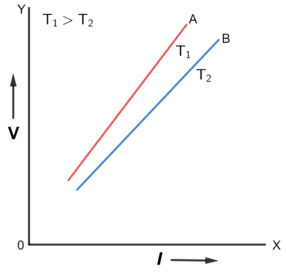
Figure shows two straight lines A and B on the V-I graph for a conductor at two different temperatures T1 and T2 (T1 > T2) respectively.
The straight line A is more steeper than the line B because the resistance of conductor is more at high temperature T1 than at low temperature T2
(a) How does the resistance of a wire depend on it's radius? Explain your answer.
(b) Two copper wires are of the same length, but one is thicker than the other. Which will have more resistance?
Answer
(a) In a thick conductor, electrons get a larger area of cross section to flow as compared to a thin conductor, therefore a thick wire offers less resistance. The resistance of a conductor is inversely proportional to it's area of cross section (a), normal to the direction of flow of current i.e.,
R ∝
Hence,
R ∝
where r is the radius of the wire.
Hence, resistance of a wire is inversely proportional to the square of the radius of the wire.
(b) As we have seen above that the resistance of a conductor is inversely proportional to it's area of cross section (a), normal to the direction of flow of current. Hence, the thin wire, will offer more resistance as it's area of cross section is less.
In a conductor, 6.25 × 10¹⁶ electrons flow from its end A to B in 2 s. Find the current flowing through the conductor. (e = 1.6 × 10⁻¹⁹ C)
Answer
Given,
- Number of electrons flowing (n) = 6.25 × 10¹⁶
- Time taken (t) = 2 s
- e = 1.6 × 10⁻¹⁹ C
Current in conductor is given by,
Substituting the values in the formula above we get,
Hence, the current flowing through the conductor is 5 mA from B to A.
A current of 3.2 mA flows through a conductor. If charge on an electron is -1.6 x 10⁻¹⁹ coulomb, find the number of electrons that will pass each second through the cross section of that conductor.
Answer
Given,
- Current (I) = 3.2 mA = 3.2 × 10⁻³ A
- Charge of one electron = -1.6 × 10⁻¹⁹ coulomb
- t = 1 s
Charge flowing through the conductor is given by,
Charge (Q) = current (I) x time (t)
Substituting the values in the formula above we get,
Q = 3.2 x 10-3 x 1 = 3.2 x 10⁻³ C
Hence,
Therefore, the number of electrons that will pass each second through the cross section of that conductor is 2 x 10¹⁶.
Find the potential difference required to flow a current of 300 mA in a wire of resistance 20 Ω.
Answer
Given,
- Current (I) = 300 mA = 0.3 A
- Resistance (R) = 20 Ω
- Potential difference (V) = ?
From Ohm's law
V = IR
Substituting the values in the formula above, we get,
V = 0.3 × 20
V = 6 V
Hence, the required potential difference is 6 V.
A car bulb connected to a 12 volt battery draws 2 A current when glowing. What is the resistance of the filament of the bulb? Will the resistance be more, same or less when the bulb is not glowing.
Answer
Given,
- Potential difference (V) = 12 V
- Current (I) = 2 A
- Resistance = ?
From Ohm's law
V = IR
Substituting the values in the formula above, we get,
12 = 2 x R
⇒ R =
⇒ R = 6 Ω
Hence, the resistance of the filament of the bulb is 6 Ω.
The resistance will be less when the bulb is not glowing.
In an experiment of verification of Ohm's law, following observations are obtained.
| Potential difference V (in volt) | 0.5 | 1.0 | 1.5 | 2.0 | 2.5 |
|---|---|---|---|---|---|
| Current I (in ampere) | 0.2 | 0.4 | 0.6 | 0.8 | 1.0 |
Draw a V-I graph and use this graph to find :
(a) the potential difference V when the current I is 0.5 A,
(b) the current I when the potential difference V is 0.75 V,
(c) the resistance in circuit.
Answer
V-I graph for the readings is shown below:
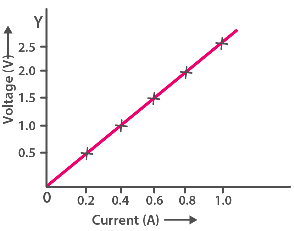
(a) We can observe from the graph that when current is 0.5 A then potential difference is 1.25 V.
(b) We can observe from the graph that when potential difference is 0.75 V, then current is 0.3 A.
(c) Slope of the graph gives the resistance, and as the graph is linear
So, if potential difference (V) = 1.0 V
current (I) = 0.4 A
From Ohm's law
V = IR
Substituting the values in the formula above, we get,
1.0 = 0.4 x R
⇒ R =
⇒ R =
⇒ R = 2.5 Ω
Hence, the resistance in circuit = 2.5 Ω
Two wires of the same material and same length have radii 1 mm and 2 mm respectively. Compare : (i) their resistances, (ii) their specific resistance.
Answer
(i) R = ρ = ρ
Resistance for wire of radius 1 mm,
R1 = ρ = ρ
Resistance for wire of radius 2 mm,
R2 = ρ = ρ
Hence, ratio between the two is :
Hence, the ratio of resistance between the two wires = 4 : 1
(ii) The specific resistance of the two wires will be same because the specific resistance is a characteristic property of the material, hence it does not change with radius.
Therefore, ratio of specific resistance between the two wires = 1 : 1
A given wire of resistance 1 Ω is stretched to double its length. What will be its new resistance?
Answer
When the wire is stretched to double it's length, it's area of cross section becomes half and it's length becomes double.
Let, a be the area of initial cross section and ρ be the specific resistance of the material of wire.
Then,
- Initial length = l
- R = 1 Ω
- New length = 2l
- New area =
From relation
R = ρ = ρ
Initial resistance (R1) = 1 = ρ [Equation 1]
New resistance (R2) = ρ = ρ [Equation 2]
On dividing eqn (2) by (1), we get,
Hence, the new resistance = 4 Ω.
A wire of resistance 3 ohm and length 10 cm is stretched to length 30 cm. Assuming that it has a uniform cross section, what will be its new resistance?
Answer
Given,
- Resistance (R) = 3 Ω
- Length (l) = 10 cm
Let, a be the area of initial cross section and ρ be the specific resistance of the material of wire.
Then,
- New length = 30 cm
- New area a =
From relation
R = ρ = ρ
Initial resistance (R1) = 3 = ρ [Equation 1]
New resistance (R2) = ρ = ρ [Equation 2]
On dividing eqn (1) by (2), we get,
Hence, the new resistance = 27 Ω
A wire of resistance 9 ohm having length 30 cm is tripled on itself. What is its new resistance?
Answer
Given,
- Resistance (R) = 9 Ω
When the wire is tripled on itself, it's area of cross section becomes thrice and it's length becomes .
Let, a be the area of initial cross section and ρ be the specific resistance of the material of wire.
Then,
- Length = 30 cm,
- New length = = = 10 cm,
- New area a2 = 3a
From relation
R = ρ
Initial resistance (R1) = 9 = ρ [Equation 1]
New resistance (R2) = ρ [Equation 2]
On dividing eqn (2) by (1), we get,
Hence, the new resistance = 1 Ω.
What length of copper wire of specific resistance 1.7 x 10⁻⁸ Ω m and radius 1 mm is required so that its resistance is 2 Ω.
Answer
Given,
- Specific resistance (ρ) = 1.7 × 10⁻⁸ Ω m
- Radius (r) = 1 mm = 10-3m
- Resistance (R) = 2 Ω
- Length (l) = ?
From relation
R = ρ = ρ
Substituting the values in the formula above we get,
Hence, the length of the copper wire is 369.4 m.
The filament of a bulb takes a current 100 mA when potential difference across it is 0.2 V. When the potential difference across it becomes 1.0 V, the current becomes 400 mA. Calculate the resistance of filament in each case and account for the difference.
Answer
Case 1 —
- Current (I) = 100 m A = 0.1 A
- Potential Difference (V) = 0.2 V
From Ohm's law
V = IR
Substituting the values in the formula above, we get,
0.2 = 0.1 x R
⇒ R =
⇒ R = 2 Ω
Hence, resistance of filament of bulb = 2 Ω
Case 2 —
- Current (I) = 400 m A = 0.4 A
- Potential Difference (V) = 1.0 V
From Ohm's law
V = IR
Substituting the values in the formula above, we get,
1.0 = 0.4 x R
⇒ R =
⇒ R = 2.5 Ω
Hence, resistance of filament of bulb = 2.5 Ω
Therefore, we observe that with increase in temperature resistance of the wire increases.
Hence, resistance of filament increases with the increase in temperature.
The specific resistance of copper, silver and constantan are 1.78 x 10⁻⁶ Ω cm, 10-6 Ω cm and 48 x 10-6 Ω cm respectively.
(i) Identify the best conductor.
(ii) Give reason for your answer above.
Answer
(i) The best conductor is silver because it has the lowest specific resistance among the three given materials.
(ii) Specific resistance (resistivity) indicates how strongly a material opposes the flow of electric current. A lower value of resistivity means less opposition to current flow and hence better conductivity.
Since silver has the smallest resistivity compared to copper and constantan, it allows electric current to pass most easily, making it the best conductor.
The current flowing through a conductor is 2 A at 50 V and 3 A at 60 V. Identify whether the conductor is ohmic or not.
Answer
Given,
- I1 = 2 A
- V1 = 50 V
- I2 = 3 A
- V2 = 60 V
To determine whether the conductor is ohmic, we check if it obeys Ohm’s law, which requires the ratio to remain constant.
On applying Ohm's law i.e, V = IR,
At 50 V and 2 A :
At 60 V and 3 A :
Since the resistance is not constant (25 Ω ≠ 20 Ω), the conductor does not obey Ohm’s law.
Therefore, the conductor is non-ohmic.
The emf of a cell depends on :
- the material of electrodes
- the shape of electrodes
- the distance between the electrodes
- the amount of electrolyte in the cell
Answer
the material of electrodes
Reason — The emf of a cell depends on :
- the material of electrodes and
- the electrolyte used in the cell.
Emf of a cell is ............... the terminal voltage when cell is not in use, while ............... the terminal voltage when cell is in use.
- greater than, smaller than
- smaller than, greater than
- equal to, greater than
- equal to, smaller than
Answer
equal to, greater than
Reason — Emf of a cell is equal to the terminal voltage when cell is not in use and when the current starts to flow in the circuit, then there is a voltage drop due to internal resistance, thus we get, V = E - Ir. Hence, Emf is greater than the terminal voltage when cell is in use.
Current drawn from the cell :
Answer
Reason — The current drawn from the cell
In series combination of resistances :
- p.d. is the same across each resistance
- total resistance is reduced
- current is same in each resistance
- all of the above are true
Answer
current is same in each resistance
Reason — Current is same in each resistance in series combination of resistances. The current has a single path to flow, hence, same current passes through each resistor.
In parallel combination of resistances :
- p.d. is the same across each resistance
- current is the same in each resistance
- total resistance is increased
- all of the above are true
Answer
p.d. is the same across each resistance
Reason — Potential difference is same across each resistor in parallel combination of resistances, which is equal to the potential difference across the terminals of the battery (or source).
For parallel combination of resistances, which of the statements are correct ?
- On I-V graph, the slope of line is more.
- The potential difference across each resistance is same.
- The current in a resistor is inversely proportional to the resistance.
- All of the above
Answer
All of the above
Reason — For parallel combination of resistances :
- On I-V graph, the slope of line is more because resistance in parallel combination is less than series combination.
- The potential difference across each resistance is same because, the ends of each resistor are connected to the ends of the same source of potential.
- According to Ohm's Law V = IR. Hence, the current in a resistor is inversely proportional to the resistance.
Assertion (A): The terminal voltage of a cell is always less than its e.m.f.
Reason (R): More the current drawn from the cell, the less is the terminal voltage.
- both A and R are true and R is the correct explanation of A
- both A and R are true and R is not the correct explanation of A
- assertion is false but reason is true.
- assertion is true but reason is false.
Answer
assertion is false but reason is true..
Explanation
Assertion (A) is false. E.m.f. is greater than the terminal voltage only when the cell delivers the current to the external circuit.
Reason (R) is true. When a heavy current is drawn from the cell, a large number of charge carriers flow through the electrolyte and hence more work is done. This results in more voltage drop v, and hence less terminal voltage V. Thus, terminal voltage V of a cell depends on the amount of current I drawn from it.
Write the expressions for the equivalent resistance R of three resistors R1, R2 and R3 joined in (a) parallel, and (b) series.
Answer
(a) Equivalent resistance R of three resistors R1, R2 and R3 joined in parallel is given by —
= + +
(b) Equivalent resistance R of three resistors R1, R2 and R3 joined in series is given by —
R = R1 + R2 + R3
State how are the two resistors joined with a battery in each of the following cases when :
(a) same current flows in each resistor,
(b) potential difference is same across each resistor,
(c) equivalent resistance is less than either of the two resistances, and
(d) equivalent resistance is more than either of the two resistances.
Answer
(a) When same current flows in each resistor, then the two resistors are joined in series
(b) When potential difference is same across each resistor, then the two resistors are joined in parallel
(c) When equivalent resistance is less than either of the two resistances, then the two resistors are joined in parallel
(d) When equivalent resistance is more than either of the two resistances, then the two resistors are joined in series
Which of the following combinations have the same equivalent resistance between X and Y?
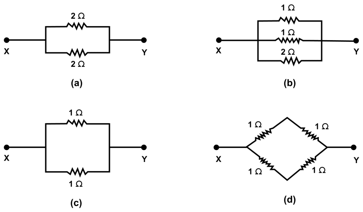
Answer
(a) In the circuit, two resistors of 2 Ω each are connected in parallel. In parallel, the equivalent resistance is RP, then
Hence, RP = 1 Ω
(b) In the circuit, three resistors of 1 Ω, 1 Ω and 2 Ω are connected in parallel. In parallel, the equivalent resistance is RP, then
Hence, RP = 0.4 Ω
(c) In the circuit two resistors of 1 Ω each are connected in parallel. In parallel, the equivalent resistance is RP, then
Hence, RP = 0.5 Ω
(d) In the circuit there are three parts. In the first part two resistor of 1 Ω each are connected in series. In series, the equivalent resistance is R'S, then
R'S = (1 + 1) Ω = 2 Ω
In the second part two resistor of 1 Ω each are connected in series. In series, the equivalent resistance is R''S, then
R''S = (1 + 1) Ω = 2 Ω
In the third part,R'S and R''S are in parallel, the equivalent resistance is RP, then
Hence, RP = 1 Ω
Therefore, on observing the values we can say that (a) and (d) have same equivalent resistances i.e., 1 Ω.
State two differences between the e.m.f. and terminal voltage of a cell.
Answer
| E.m.f of cell | Terminal voltage of cell |
|---|---|
| It is measured by the amount of work done per unit change in moving a positive test charge in the complete circuit inside and outside the cell. | It is measured by the amount of work done per unit charge in moving a positive test charge in the circuit outside the cell. |
| It is the the characteristic of the cell, i.e., it does not depend on the amount of current drawn from the cell. | It depends on the amount of current drawn from the cell. More the current drawn from the cell, less is the terminal voltage. |
Name two factors on which the internal resistance of a cell depends and state how does it depend on the factors stated by you.
Answer
The factors on which the internal resistance of a cell depends are —
- The surface area of the electrodes — larger the surface area of electrodes, less is the internal resistance.
- The distance between the electrodes — more the distance between the electrodes, greater is the internal resistance.
A cell of e.m.f. ε and internal resistance r is used to send current to an external resistance R. Write expressions for (a) the total resistance of circuit, (b) the current drawn from the cell, (c) the p.d. across the cell, and (d) voltage drop inside the cell.
Answer
Given,
- e.m.f. = ε
- internal resistance = r
- external resistance = R
(a) The total resistance of circuit = R + r
(b) The current drawn from the cell
(c) the p.d. across the cell = V = IR
Substituting from above,
(d) Voltage drop inside the cell V = Ir
Substituting from above,
A cell is used to send current to an external circuit. (a) How does the voltage across its terminals compare with its e.m.f.? (b) Under what condition is the e.m.f. of the cell equal to its terminal voltage?
Answer
(a) When a cell is used to send current to an external circuit, it's terminal voltage V is less than it's e.m.f.
Hence, terminal voltage < e.m.f.
(b) The emf of the cell is equal to it's terminal voltage when no current is drawn.
The V-I graph for a series combination and for a parallel combination of two resistors is shown in figure. Which of the two, A or B, represents the parallel combination? Give a reason for your answer.
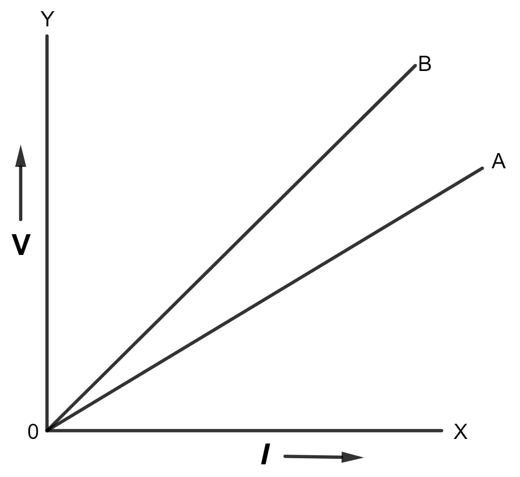
Answer
The slope of V-I graph gives the resistance. Since the straight line A is less steeper than B, so the straight line A represents small resistance. In parallel combination, the equivalent resistance is less than in series combination so A represents the parallel combination.
Explain the meaning of the terms e.m.f., terminal voltage, and internal resistance of a cell.
Answer
e.m.f — e.m.f of a cell is defined as the energy spent (or the work done) per unit charge in taking a positive test charge around the complete circuit of the cell. (i.e., in the circuit outside the cell as well as in the electrolyte inside the cell).
Terminal voltage — The terminal voltage of a cell is defined as the work done per unit charge in carrying a positive test charge around the circuit connected across the terminals of the cell.
Internal resistance — The resistance offered by the electrolyte inside the cell, to the flow of current, is known as the internal resistance of the cell.
Explain why is the p.d. across the terminals of a cell is more in an open circuit and reduced in a closed circuit.
Answer
In a closed circuit, the current flows through the circuit. There is a fall of potential across the internal resistance of the cell. Hence, the p.d. across the terminals in a closed circuit is less than the p.d. across the terminals in an open circuit by an amount equal to the potential drop across the internal resistance of the cell.
Hence, the p.d. across the terminals of a cell is more in an open circuit and reduced in a closed circuit.
How would you connect two resistors in series? Draw a diagram. Calculate the total equivalent resistance.
Answer
Below diagram shows two resistors connected in series:
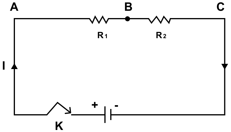
If current I is drawn from the battery, the current through each resistor will also be I.
By Ohm's law,
p.d. between A and B is V1 = VA - VB = IR1
p.d. between B and C is V2 = VB - VC = IR2
Adding these we get,
V = V1 + V2
= VA - VB + VB - VC
= VA - VC
= IR1 + IR2
= I (R1 + R2) [Equation 1]
If the equivalent resistance between the points A and C is RS, then the potential difference between the points A and C is
V = VA - VC = IRS [Equation 2]
Therefore from equation 1 and 2,
IRS = I (R1 + R2)
⇒ RS = R1 + R2
Thus, in the series combination, the equivalent resistance is equal to the sum of the individual resistances.
Show by a diagram how two resistors R1 and R2 are joined in parallel. Obtain an expression for the total resistance of combination.
Answer
Below diagram shows two resistors connected in parallel:
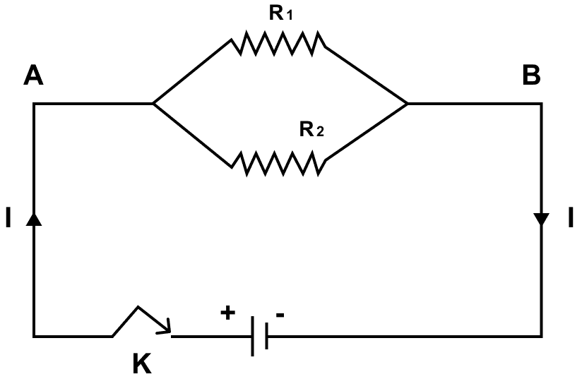
Let I1 and I2 be the currents through the resistances R1 and R2 respectively, then total current drawn from the battery is
I = I1 + I2 [Equation 1]
If potential difference between the two ends A and B is V, then by Ohm's law
current in R1 is I1 =
current in R2 is I2 =
On adding these,
I1 + I2 = + [Equation 2]
If the equivalent resistance of the combination between the points A and C is Rp, then total current drawn from the source is
I = [Equation 3]
Substituting the values of I and I1 + I2 from equation 3 and 2 in 1, we get,
Thus, in the parallel combination, the reciprocal of the equivalent resistance is equal to the sum of the reciprocals of the individual resistances.
The diagram in below figure shows a cell of e.m.f. ε = 4 volt and internal resistance r = 2 ohm connected to an external resistance R = 8 ohm. The ammeter A measures the current in the circuit and the voltmeter V measures the terminal voltage across the cell. What will be the readings of the ammeter and voltmeter when (i) the key K is open, and (ii) the key K is closed.
Answer
Given,
- e.m.f. (ε) = 4 volt
- Internal resistance (r) = 2 ohm
- External resistance (R) = 8 ohm
(i) When the key is open then no current is flowing in the circuit and hence the ammeter reading = 0
From relation,
Voltage (V) = ε – Ir
Substituting the values in the formula we get,
V = 4 – (0 × 2)
V = 4 volt
Hence, voltmeter reading is 4 volt.
(ii) When key is closed, current drawn from the cell,
Substituting the values in the formula above we get,
I =
⇒ I =
⇒ I = 0.4 ampere
Thus, ammeter reading = 0.4 ampere
From relation,
Voltage (V) = ε – Ir
Substituting the values in the formula we get,
V = 4 - (0.4 x 2) = 3.2 V
Hence, voltmeter reading is 3.2 volt.
A battery of e.m.f. 6.0 V supplies current through a circuit in which the resistance can be changed. A high resistance voltmeter is connected across the battery. When the current is 3 A, the voltmeter reads 5.4 V. Find the internal resistance of the battery.
Answer
Given,
- E.m.f. (ε) = 6.0 V
- Current (I) = 3 A
- Potential difference (V) = 5.4 V
- Internal resistance (r) = ?
From relation,
V = ε – Ir
Substituting the values in the formula above we get,
5.4 = 6 - (3r)
⇒ r = 6 - 5.4
⇒ 3r = 0.6
⇒ r =
⇒ r =
⇒ r =
⇒ r = 0.2 Ω
Hence, internal resistance of the battery is 0.2 Ω.
A cell of emf 1.8 V and internal resistance 2 Ω is connected in series with an ammeter of resistance 0.7 Ω and resistance of 4.5 Ω as shown in below figure.
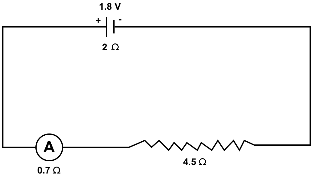
(a) What would be the reading of the ammeter?
(b) What is the potential difference across the terminals of the cell ?
Answer
(a) Given,
- e.m.f. (ε) = 1.8 V
- Internal resistance (r) = 2 Ω
- I = ?
Total resistance of arrangement = 2 + 0.7 + 4.5 = 7.2 Ω
From relation,
Substituting the values in the formula above we get,
I =
⇒ I = 0.25 A
Hence, reading of ammeter = 0.25 A
(b) Current (I) = 0.25 A
total resistance (excluding internal resistance) = 4.5 + 0.7 = 5.2 ohm
Using ohm's law
V = IR
Substituting the values in the formula above we get,
V = 0.25 × 5.2
V = 1.3 V
Hence, potential difference across the terminals of the battery is 1.3 V.
The music system draws a current of 400 mA when connected to a 12 V battery.
(a) What is the resistance of the music system ?
(b) The music system if left playing for several hours and finally the battery voltage drops and the music system stops playing when the current drops to 320 mA. At what battery voltage does the music system stop playing.
Answer
(a) Given,
- I = 400 mA = 400 x 10-3 = 0.4 A
- V = 12 V
From Ohm's law,
V = IR
Substituting the values in the formula we get,
12 = 0.4 x R
⇒ R =
⇒ R = 30 Ω
Hence, the resistance of the music system is 30 Ω.
(b) Given,
- I = 320 mA = 320 x 10-3 A = 0.32 A
- R = 30 Ω
From Ohm's law,
V = IR
Substituting the values in the formula we get,
V = 0.32 x 30 = 9.6V
Hence, the battery voltage when the music system stops playing is 9.6 V.
A cell of e.m.f. ε and internal resistance r sends a current of 1.0 A when it is connected to an external resistance of 1.9 ohm. But it sends a current of 0.5 A when it is connected to an external resistance of 3.9 ohm. Calculate the values of ε and r.
Answer
Given,
- e.m.f. = ε
- Internal resistance = r
- Current (I) = 1.0 A
- External resistance (R) = 1.9 ohm
Case 1 :
From relation,
ε = I(R + r)
Substituting the value in the formula above we get,
ε = 1 x (1.9 + r)
ε = 1.9 + r [Equation 1]
Case 2 :
- I = 0.5 A
- R = 3.9 Ω
Substituting the value in the formula above we get,
ε = 0.5 x (3.9 + r)
ε = 1.95 + 0.5r [Equation 2]
Equating 1 and 2 we get,
Now, substituting the value of r in equation 1, we get,
ε = 1.9 + 0.1
ε = 2 V
Hence, ε = 2 V , r = 0.1 Ω
You have three resistors of values 2 Ω, 3 Ω, and 5 Ω. How will you join them so that the total resistance is less than 1 Ω ? Draw a diagram and find the total resistance.
Answer
In order to get a total resistance less than 1 Ω, the three resistors of values 2 Ω, 3 Ω and 5 Ω, should be connected in parallel as shown in the diagram below:

In parallel, if the equivalent resistance is RP, then
Hence, the three resistors should be connected in parallel and total resistance is 0.97 Ω.
Three resistors each of 2 Ω are connected together so that their total resistance is 3 Ω. Draw a diagram to show this arrangement and check it by calculation.
Answer
When two resistors (2 Ω each) in parallel combination are connected to the third resistor (2 Ω) in series connection then the resultant resistance is 3 Ω. The below diagram shows this arrangement of resistors:
To verify,
Total resistance of two resistors in parallel,
In parallel, if the equivalent resistance is RP, then
Thus, RP = 1 Ω
In series connection,
Equivalent resistance = RE = RP + R3 = 1 + 2 = 3 Ω
Hence, equivalent resistance = 3 Ω
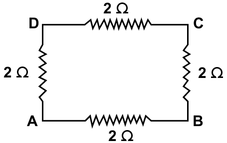
Calculate the equivalent resistance between the points A and B in bewlo figure if each resistance is 2.0 Ω.
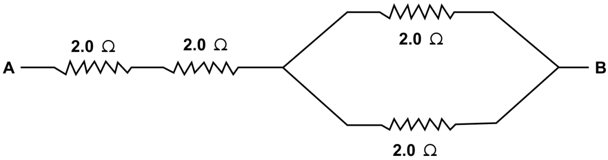
Answer
Let the resistors be R1, R2, R3, R4 each of 2.0 Ω.
In parallel, if the equivalent resistance is RP, then
Thus, RP = 1 Ω
In series connection,
Equivalent resistance = RE = R1 + R2 + RP = 2 + 2 + 1 = 5 Ω
Hence, equivalent resistance = 5 Ω
A combination consists of three resistors in series. Four similar sets are connected in parallel. If the resistance of each resistor is 2 ohm, find the resistance of the combination.
Answer
Let the four set of resistors be R1, R2, R3, R4 .
As each set consists of three resistors of 2 Ω each in series:
Resistance of each set = 2 + 2 + 2 = 6 Ω
As four similar sets of equivalent resistance 6 Ω are arranged in parallel, so the equivalent resistance (RP) will be:
Hence, equivalent resistance = 1.5 Ω
In the circuit shown below in figure, calculate the value of x if the equivalent resistance between the points A and B is 4 Ω.
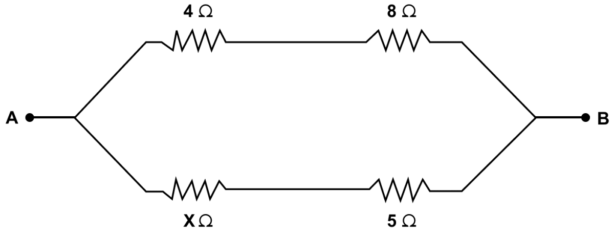
Answer
In the circuit, there are three parts. In the first part, resistors of 4 Ω and 8 Ω are connected in series. If the equivalent resistance of this part is R's then
R's = 4 + 8 = 12 Ω
In the second part, resistors of x Ω and 5 Ω are connected in series. If the equivalent resistance of this part is R''s then
R''s = (x + 5) Ω
In the third part, the two parts of resistance R's = 12 Ω and R''s = (x + 5) Ω are connected in parallel. If the equivalent resistance between points A and B is Rp then
But it is given that equivalent resistance between points A and B is 4 Ω
∴ Rp = 4 Ω
Putting value of Rp in the equation above and solving for x:
Hence, the value of x = 1 Ω
Calculate the effective resistance between the points A and B in the circuit shown in below figure.
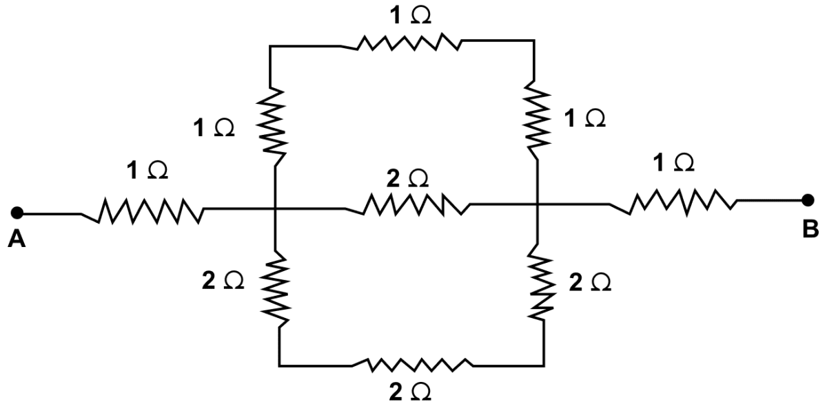
Answer
In the circuit, there are four parts. In the first part, three resistors of 1 Ω each are connected in series. If the equivalent resistance of this part is R's then
R's = (1 + 1 + 1) Ω = 3 Ω
In the second part, three resistors of 2 Ω each are connected in series. If the equivalent resistance of this part is R''s then
R''s = (2 + 2 + 2) Ω = 6 Ω
In the third part, the two parts of resistance R's = 3 Ω and R''s = 6 Ω and 2 Ω are connected in parallel. If the equivalent resistance is Rp then
∴ Rp = 1 Ω
In the fourth part 1 Ω, (Rp = 1 Ω) and 1 Ω are connected in series in between points A and B.
Hence, the equivalent resistance is (1 + 1 + 1) Ω = 3 Ω
A uniform wire with a resistance of 27 Ω is divided into three equal pieces and then they are joined in parallel. Find the equivalent resistance of the parallel combination.
Answer
Given,
- Uniform wire with a resistance of 27 Ω is divided into three equal pieces. Hence, resistance of each piece = 9 Ω.
Three such pieces are joined in parallel.
In parallel, if the equivalent resistance is RP, then
Hence, equivalent resistance = 3 Ω
A circuit consists of a resistor of 1 ohm in series with a parallel arrangement of resistors of 12 ohm and 6 ohm. Calculate the total resistance of the circuit. Draw a diagram of the arrangement.
Answer
Below diagram shows the arrangement of resistors:

In the circuit, there are two parts. In the first part, two resistors of 6 Ω and 12 Ω are connected in parallel. If the equivalent resistance is Rp then
Thus, RP = 4 Ω
In the second part, 1 Ω and (RP = 4 Ω) are connected in series. If the equivalent resistance is Rs then
Rs = 1 + RP = 1 + 4 = 5 Ω
Hence, total resistance of the circuit = 5 Ω
Calculate the effective resistance between the points A and B in the network shown below in figure.
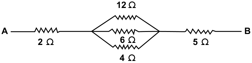
Answer
In the circuit, there are two parts. In the first part, resistors of 12 Ω, 6 Ω and 4 Ω are connected in parallel. If the equivalent resistance of this part is R'p then
Thus, R'P = 2 Ω
In the second part, resistors of 2 Ω, (R'p = 2Ω) and 5 Ω are connected in series. If the equivalent resistance of this part is Rs then
Rs = (2 + 2 + 5) Ω = 9 Ω
Hence, effective resistance between A and B = 9 Ω
Calculate the equivalent resistance between the points A and B in below figure.
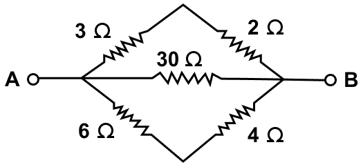
Answer
In the circuit, there are three parts. In the first part, two resistors of 3 Ω, 2 Ω are connected in series. If the equivalent resistance is R's then
R's = 3 + 2 = 5 Ω
In the second part, two resistors of 6 Ω, 4 Ω are connected in series. If the equivalent resistance is R''s then
R''s = 6 + 4 = 10 Ω
In the third part R's, 30 Ω and R''s are connected in parallel. If the equivalent resistance is Rp then
Hence, RP = 3 Ω
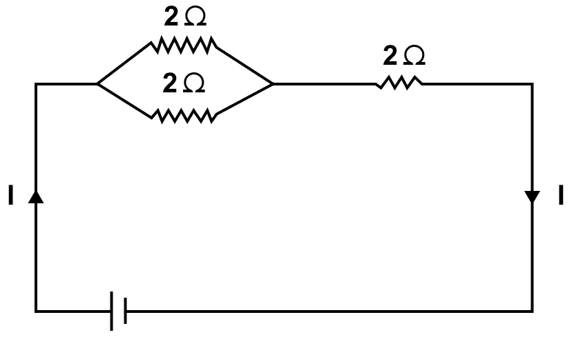
In the network shown in below figure, calculate the equivalent resistance between the points (a) A and B, and (b) A and C.
Answer
In the circuit, there are two parts. In the first part, three resistors of 2 Ω each are connected in series. If the equivalent resistance of this part is R's then
R's = (2 + 2 + 2) Ω = 6 Ω
In the second part, the resistance of first part (R's = 6 Ω ) and 2 Ω are connected in parallel. If the equivalent resistance of this part is Rp then
∴ Rp = 1.5 Ω
(b) In the circuit, there are three parts. In the first part, two resistors of 2 Ω each are connected in series. If the equivalent resistance of this part is R's then
R's = (2 + 2) Ω = 4 Ω
In the second part, two resistors of 2 Ω each are connected in series. If the equivalent resistance of this part is R''s then
R''s = (2 + 2) Ω = 4 Ω
In the third part, the two parts of resistance R's = 4 Ω and R''s = 4 Ω are connected in parallel. If the equivalent resistance between points A and C is Rp then
∴ Equivalent Resistance between A and C = 2 Ω
Five resistors, each of 3 ohm, are connected as shown in below figure. Calculate the resistance (a) between the points P and Q, and (b) between the points X and Y.
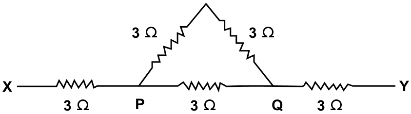
Answer
(a) In the circuit, there are two parts. In the first part, two resistors of 3 Ω each are connected in series. If the equivalent resistance of this part is R's then
R's = (3 + 3) Ω = 6 Ω
In the second part, resistance R's = 6 Ω and 3 Ω are connected in parallel. If the equivalent resistance between points P and Q is Rp then
∴ Equivalent resistance between the points P and Q = 2 Ω
(b) In the circuit, 3 Ω, Rp = 2 Ω and 3 Ω are connected in series. If the equivalent resistance of this part is Rs then
Rs = (3 + 2 + 3) Ω = 8 Ω
∴ Equivalent resistance between the points X and Y = 8 Ω
Two resistors of resistance 2 Ω and 3 Ω are connected in parallel to a cell to draw 0.5 A current from the cell.
(a) Draw a labelled diagram of the arrangement.
(b) Calculate the current in each resistor.
Answer
(a) Labelled diagram of the arrangement is shown below:

(b) Two resistors of 2 Ω and 3 Ω are connected in parallel. If the equivalent resistance of this part is Rp then
So,
- Equivalent resistance = 1.2 Ω
- Current (I) = 0.5 A
- Potential Difference (V) = ?
From Ohm's law
V = IR
Substituting the values in the formula above, we get,
V = 0.5 x 1.2 = 0.6 V
Current through 2 Ω = ?
From Ohm's law
V = IR
Substituting the values in the formula above, we get,
0.6 = I x 2
⇒ I = = 0.3 A
Thus, current through 2 Ω resistor = 0.3 A
Current through 3 Ω = ?
From Ohm's law
V = IR
Substituting the values in the formula above, we get,
0.6 = I x 3 ⇒ I = = 0.2 A
Hence, current through 3 Ω resistor = 0.2 A
Calculate the current flowing through each of the resistors A and B in the circuit shown in below figure.
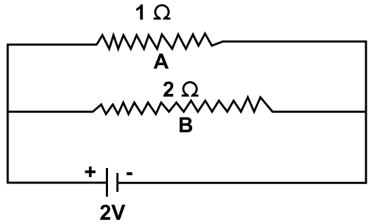
Answer
(a) Given,
- R = 1 Ω
- V = 2 V
- Current through 1 Ω = ?
From Ohm's law
V = IR
Substituting the values in the formula above, we get,
2 = I x 1
⇒ I = 2 A
So, current through Resistor A = 2 A
(b) Given,
- R = 2 Ω
- V = 2 V
- Current through 2 Ω = ?
From Ohm's law
V = IR
Substituting the values in the formula above, we get,
2 = I x 2
⇒ I = = 1 A
Hence, current through Resistor B = 1 A
In bewlo figure, calculate —
(a) the total resistance of the circuit,
(b) the value of R, and
(c) the current flowing in R.
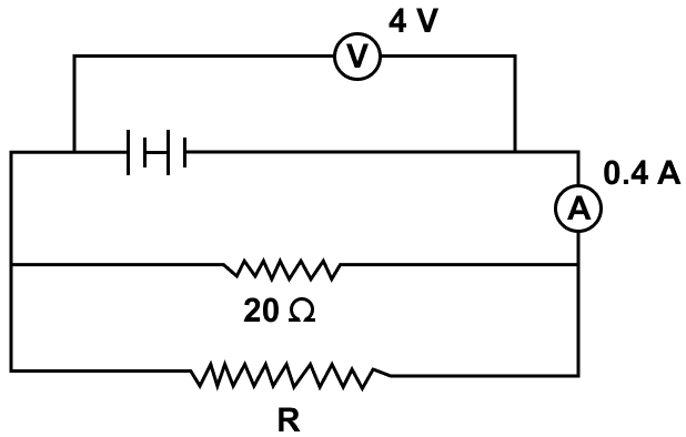
Answer
(a) Given,
- V = 4 V
- I = 0.4 A
From Ohm's law
V = IR
4 = 0.4 x R
⇒ R = = 10 Ω
Hence, total resistance of the circuit = 10 Ω
(b) As total resistance of the circuit is equal to 10 Ω and the two resistors R and 20 Ω are connected in parallel, hence we get,
Hence, the value of R = 20 Ω
(c) current flowing in R = ?
- V = 4 V
- R = 20 Ω
- I = ?
From Ohm's law
V = IR
⇒ 4 = I x 20
⇒ I = = 0.2 A
Hence, the current flowing in R = 0.2 A
A particular resistance wire has a resistance of 3.0 ohm per meter. Find —
(a) The total resistance of three lengths of this wire each 1.5 m long, joined in parallel.
(b) The potential difference of the battery which gives a current of 2.0 A in each of the 1.5 m length when connected in parallel to the battery (assume that the resistance of battery is negligible).
(c) The resistance of 5 m length of a wire of the same material, but with twice the area of cross section.
Answer
(a) Resistance of 1 m of wire = 3 Ω.
Resistance of 1.5 m of wire = 3 x 1.5 = 4.5 Ω. As three such wires are joined in parallel and if the equivalent resistance of this part is Rp then
Hence, total resistance of circuit = 1.5 Ω
(b) I = 2 A
From Ohm's Law
V = IR
Substituting the values in the formula above we get,
V = 2 x 4.5 = 9 V
Hence, potential difference = 9 V
(c) R = 3 Ω for 1 meter wire
Therefore, for 5 m
R = 3 x 5 = 15 Ω
Here the area is twice and resistance is inversely proportional to area.
Thus, resistance becomes half
R = = 7.5 Ω
Hence, resistance = 7.5 Ω
A cell supplies a current of 1.2 A through two resistors each of 2 Ω connected in parallel. When the resistors are connected in series, it supplies a current of 0.4 A. Calculate : (i) the internal resistance, and (ii) e.m.f. of the cell.
Answer
(i) Given,
Two resistors each of 2 Ω connected in parallel. If the equivalent resistance of this part is Rp then
So, equivalent resistance Rp = 1 Ω
Given,
- I = 1.2 A
From relation,
ε = I(R + r)
= 1.2 x (1 + r)
= 1.2 + 1.2r [Equation 1]
When the resistors are connected in series, it supplies a current of 0.4 A,
If the equivalent resistance of this part is Rs then
Rs = 2 + 2 = 4 Ω
Thus, equivalent resistance Rs = 4 Ω
Given,
- I = 0.4 A
From relation,
ε = I(R + r)
= 0.4 x (4 + r)
= 1.6 + 0.4r [Equation 2]
Equating 1 and 2, we get,
1.2 + 1.2r = 1.6 + 0.4r
⇒ 1.2r – 0.4r = 1.6 - 1.2
⇒ 0.8r = 0.4
⇒ r =
⇒ r = 0.5 Ω
Hence, internal resistance r = 0.5 Ω
(ii) Substituting the value in equation 1 we get,
ε = 1.2(1 + r)
= 1.2 x (1 + 0.5)
= 1.2 x 1.5
= 1.8 V
Hence, e.m.f. of the cell = 1.8 V
A battery of e.m.f. 16 V and internal resistance 2 Ω is connected to two resistors 3 Ω and 6 Ω connected in parallel. Find : (a) the current through the battery, (b) the p.d. between the terminals of the battery, (c) the current in 3 Ω resistor, (d) the current in 6 Ω resistor.
Answer
(a) Given,
- e.m.f. = 16 V
- Internal resistance = 2 Ω
- Current through battery = ?
If Rp is the equivalent resistance of resistors 3 Ω and 6 Ω connected in parallel, then
From relation,
ε = I(R + r)
Substituting the value in the formula above we get,
16 = I(2 + 2)
⇒ 16 = I x 4
⇒ I = = 4 A
Hence, current through the battery = 4 A
(b) Potential difference between the terminals of the battery = ?
Using Ohm's law
V = IR
- R = 2 Ω
- I = 4 A
Substituting the values in the formula above we get,
V = 4 x 2 = 8 V
Hence, potential difference between the terminals of the battery = 8 V
(c) Current in 3 Ω resistor = ?
Using Ohm's law
V = IR
- R = 3 Ω
- V = 8 V
- I = ?
Substituting the values in the formula above we get,
8 = I × 3
I =
⇒ I = 2.66 A
Hence, current in 3 Ω resistor is 2.66 A
(d) Current in 6 Ω resistor = ?
Using Ohm's law
V = IR
- R = 6 Ω
- V = 8 V
- I = ?
Substituting the values in the formula above we get,
8 = I × 6
⇒ I = = 1.333 A
Hence, current in 6 Ω resistor is 1.34 A
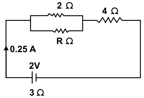
The circuit diagram in below figure shows three resistors 2 Ω, 4 Ω and R Ω connected to a battery of e.m.f. 2V and internal resistance 3 Ω. If main current of 0.25 A flows through the circuit, find :
(a) the p.d. across the 4 Ω resistor,
(b) the p.d. across the internal resistance of the cell,
(c) the p.d. across the R Ω or 2 Ω resistor, and
(d) the value of R.
Answer
(a) Given,
- R = 4 Ω
- I = 0.25 A
- The p.d. across the 4 Ω resistor (V) = ?
Using Ohm's law
V = IR
Substituting the values in the formula above we get,
V = 0.25 x 4 = 1 V
Hence, the p.d. across the 4 Ω resistor (V) = 1 V
(b) Given,
- Internal resistance = 3 Ω
- I = 0.25 A
- The p.d. across the internal resistance of the cell = ?
Using Ohm's law
V = IR
Substituting the values in the formula above we get,
V = 0.25 x 3 = 0.75 V
Hence, the p.d. across the internal resistance (V) = 0.75 V
(c) Potential difference across R Ω or 2 Ω
V = Vnet - Vacross 4 Ω - Vacross 3 Ω
Hence, we get,
V = 2 - 1 - 0.75 = 0.25 V
(d) The p.d. across resistor of R Ω = 0.25 V
Let the equivalent resistance of the resistors of 2 Ω and R Ω connected in parallel be R'p
Using Ohm's law
V = IR
0.25 = 0.25 x R'p
Substituting the value of R'p from above:
Hence, value of R = 2 Ω
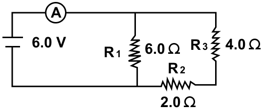
Three resistors of 6.0 Ω, 2.0 Ω and 4.0 Ω are joined to an ammeter A and a cell of e.m.f. 6.0 V as shown in figure. Calculate —
(a) the effective resistance of the circuit, and
(b) the reading of ammeter.
Answer
(a) In the circuit, there are two parts. In the first part, resistors of 2.0 and 4.0 Ω are connected in series. If the equivalent resistance of this part is Rs then
Rs = 2 + 4 = 6 Ω
In the second part, Rs = 6.0 and resistor of 6.0 Ω are connected in parallel. If the equivalent resistance of this part is Rp then
Hence, the effective resistance of the circuit = 3 Ω
(b) The reading of ammeter = ?
- R = 3 Ω
- V = 6.0 V
Using Ohm's law,
V = IR
Substituting the values in the formula above we get,
6 = I x 3
⇒ I = = 2 A
Hence, the reading of ammeter = 2 A
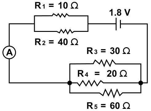
The diagram below in figure shows the arrangement of five different resistances connected to a battery of e.m.f. 1.8 V. Calculate :
(a) the total resistance of the circuit, and
(b) the reading of ammeter A.
Answer
(a) In the circuit, there are three parts. In the first part, resistors of 10 Ω and 40 Ω are connected in parallel. If the equivalent resistance of this part is R'p then
In the second part, resistors of 30 Ω, 20 Ω and 60 Ω are connected in parallel. If the equivalent resistance of this part is R''p then
In the third part, resistors R'p and R''p are connected in series. If the equivalent resistance of this part is Rs then
Hence, the total resistance of the circuit = 18 Ω
(b) Given,
- E.m.f. = 1.8 V
- Effective resistance of the circuit = 18 Ω
- I = ?
From Ohm's law
V = IR
Substituting the values in the formula above, we get,
1.8 = I x 18
I =
⇒ I = 0.1 A
Hence, the reading of ammeter = 0.1 A
A cell of e.m.f. 2 V and internal resistance 1.2 Ω is connected to an ammeter of resistance 0.8 Ω and two resistors of 4.5 Ω and 9 Ω as shown in below figure.
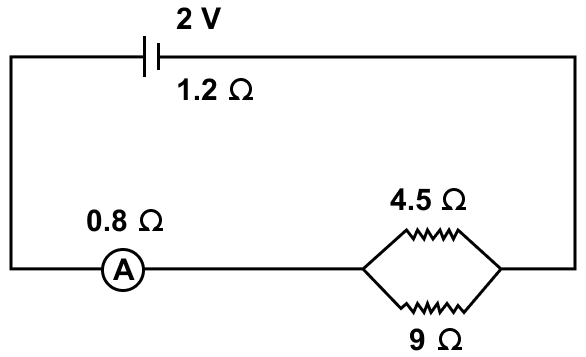
Find :
(a) the reading of the ammeter,
(b) the potential difference across the terminals of the cell, and
(c) the potential difference across the 4.5 Ω resistor.
Answer
(a) Given,
- e.m.f. = 2 V
- I = ?
In the circuit, there are two parts. In the first part, resistors of 4.5 Ω and 9 Ω are connected in parallel. If the equivalent resistance of this part is Rp then
In the second part, 1.2 Ω, 0.8 Ω and Rp = 3 Ω are connected in series. If the equivalent resistance of this part is Rs then
So, the effective resistance of the circuit = 5 Ω
Using Ohm's law,
V = IR
2 = I x 5
⇒ I =
⇒ I = 0.4 A
Hence, the reading of the ammeter = 0.4 A
(b) The potential difference across the ends of the cells = ?
- ε = 2 V
- I = 0.4 A
- r = 1.2 Ω
From relation,
Voltage (V) = ε – Ir
Substituting the values in the formula we get,
V = 2 - (0.4 x 1.2)
⇒ V = 2 - 0.48
⇒ V = 1.52 V
Hence, potential difference across the terminals of the cell = 1.52 V
(c) The potential difference across the 4.5 Ω resistor = ?
Current flowing is I = 0.4 A.
Now the current I divides in two parts.
Let the current in 4.5 Ω resistor be I1 and in 9 Ω resistor be I2.
So,
I = I1 + I2
And
I1 x 4.5 = I2 x 9
On solving,
Alternate Method:
V4.5Ω = Vcell - Vammeter
Hence, p.d. across the 4.5 Ω resistor = 1.2 V
You have installed a new battery of emf 12 V and internal resistance 5.0 x 10⁻² Ω in your car. You self-start your car and it draws a current of 90 A. What would be the teminal voltage of battery when the self-starter is working ?
Answer
- Emf of the battery (ε) = 12 V
- Internal resistance of the battery (r) = 5.0 x 10⁻² Ω
- Current drawn (I) = 90 A
As, terminal voltage (V) of the battery is given by,
Hence, the teminal voltage of battery is 7.5 V.
The electrical energy supplied by a source is given by:
- W = QV
- W = VIt
- W = I2Rt
- All of the above
Answer
All of the above
Reason — We know,
- W = QV
As, Q = It
Hence, substituting we get
- W = VIt
And By Ohm's Law : V = IR
Hence, substituting we get
- W = (IR)It = I2Rt
1 WH is equal to :
- 3600 J
- 360 J
- 36 J
- 3.6 J
Answer
3600 J
Reason — 1 watt-hour = 1 watt x 1 hour = 1 W x (60 x 60 s) = 3600 J
Hence, 1 WH = 3600 J
The amount of heat produced in a wire on passing a current through it depends on:
- the resistance of wire
- the square root of current I passing through the wire.
- the time for which current is passed.
- both the resistance of the wire and the duration for which current flows
Answer
both the resistance of the wire and the duration for which current flows
Reason — The amount of heat produced in a wire on passing current through it, depends on the following three factors.
- The amount of current passing through the wire — The amount of heat H produced in a wire is directly proportional to the square of current I passing through the wire, i.e., H ∝ I2
- The resistance of wire — The amount of heat H produced in the wire is directly proportional to the resistance R of the wire, i.e., H ∝ R.
- The time for which current is passed in the wire — The amount of heat H produced in a wire is directly proportional to the time t for which current is passed in the wire i.e., H ∝ t
An electrical appliance has a rating 100 W, 120 V. The resistance of element of appliance when in use is :
- 1.2 Ω
- 144 Ω
- 120 Ω
- 100 Ω
Answer
144 Ω
Reason — Resistance of an electrical appliance (rating 100 W, 120 V) is :
Substituting the values in the formula above we get,
Hence, the resistance of an electrical appliance is 144 Ω.
A bulb is rated 100 W-220 V. It is being used at 110 V supply. The power consumed by bulb is:
- 100 W
- half of 100 W
- nearly 25 W
- none of the above
Answer
nearly 25 W
Reason — Given,
- Power (P) = 100 W
- Voltage (V) = 220 V
We know that,
Power (P) = VI
Substituting the values in the formula above, we get,
100 = 220 x I
⇒ I =
⇒ I = 0.45 A
Therefore, current through the lamp = 0.45 A
Power consumed when voltage is 110 V = ?
Substituting the values in the formula, we get,
From relation,
Substituting the values in the formula, we get,
Hence, the power consumed is 25 W.
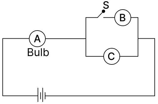
Three bulbs A, B and C are connected as shown in the figure. What changes are seen in brightness of the bulbs if switch S is closed?
- The brightness of bulb A decreases and that of C increases.
- The brightness of bulb A increases but that of C decreases.
- The brightness of both bulbs A and C decreases.
- The brightness of both bulbs A and C remains the same.
Answer
The brightness of bulb A increases but that of C decreases.
Reason — When switch S is open, bulb B is out of the circuit, so bulbs A and C are in series. When the switch is closed, bulbs B and C form a parallel combination. This reduces the equivalent resistance of that part of the circuit, so the total resistance of the circuit decreases.
As a result, the current in the main circuit increases. Since bulb A is in series with the whole circuit, it gets more current and glows brighter.
But after closing the switch, the current in the right-hand part divides between bulbs B and C. Therefore, the current through bulb C decreases, so its brightness decreases.
Hence, the brightness of bulb A increases while that of bulb C decreases.
A bulb B1 100 W, bulb B2 60 W and bulb B3 40 W are connected as shown in the figure. The output powers of these would be :

- W1 < W2 < W3
- W1 = W2 > W3
- W1 > W2 > W3
- W1 > W2 = W3
Answer
W1 < W2 < W3
Reason — The bulbs B1 and B2 are connected in series in the upper branch, while bulb B3 is connected in a parallel branch directly across the 240 V supply.
For bulbs of the same voltage rating,
So, resistance is inversely proportional to power.
Thus,
- 100 W bulb has the least resistance
- 60 W bulb has greater resistance
- 40 W bulb has the greatest resistance
Hence,
R1 < R2 < R3
Since B1 and B2 are in series, the same current flows through both. Power in a series circuit is given by:
P=I2R
Therefore, the bulb with greater resistance in that branch will consume more power.
So,
W2 > W1
Bulb B3 is connected directly across the mains, so it gets the full 240 V and works at its rated power, i.e. 40 W.
But B1 and B2, being in series, share the voltage, so each consumes less power than B3.
Therefore, the output powers are in the order : W1 < W2 < W3.
Assertion (A): In series combination of electric bulbs, the bulb of lower power emits more light than that of the higher power.
Reason (R): The lower power bulb in series gets more current than the higher power bulb
- both A and R are true and R is the correct explanation of A
- both A and R are true and R is not the correct explanation of A
- assertion is false but reason is true
- assertion is true but reason is false
Answer
assertion is true but reason is false.
Explanation
In a series circuit, the same current flows through all the bulbs.
For bulbs of the same voltage rating,
So, the bulb of lower power rating has higher resistance.
Now, the power consumed in a series circuit is:
P=I2R
Since the current I is the same through each bulb, the bulb having greater resistance consumes more power and therefore glows brighter.
Hence, the lower power bulb emits more light than the higher power bulb in series. So, the Assertion is true.
The Reason is false because the lower power bulb does not get more current. In series combination, current is the same through every bulb.
Hence, assertion is true but reason is false.
Assertion (A): In parallel combination of electrical appliances, total power consumption is equal to the sum of the power of individual appliances.
Reason (R): In parallel combination, the voltage across each appliance is the same.
- both A and R are true and R is the correct explanation of A
- both A and R are true and R is not the correct explanation of A
- assertion is false but reason is true
- assertion is true but reason is false
Answer
both A and R are true and R is the correct explanation of A
Explanation
Assertion (A) is true because in a parallel combination, each appliance operates independently and draws its own current. The total current supplied by the source is the sum of currents in all branches. Since total power is given by P = VI, the total power consumed becomes the sum of the individual powers of all appliances.
Reason (R) is true because in a parallel circuit, each appliance is connected directly across the source, so the same potential difference (voltage) is applied across each appliance.
Hence, both A and R are true and R is the correct explanation of A.
Write an expression for the electrical energy spent in flow of current through an electrical appliance in terms of current, resistance and time.
Answer
The expression for electrical energy spent in flow of current through an electrical appliance in terms of current, resistance and time is:
W = I2Rt
Write an expression for the electrical power spent in flow of current through a conductor in terms of (a) resistance and potential difference, (b) current and resistance.
Answer
(a) Expression for electrical power spent in flow of current through a conductor in terms of resistance and potential difference is —
(b) Expression for electrical power spent in flow of current through a conductor in terms of current and resistance is —
State the S.I. unit of electrical power.
Answer
The S.I. unit of electrical power is volt x ampere (VA) or watt (W) or J s-1
One watt is the electric power consumed when a current of 1 ampere flows through a circuit having a potential difference of 1 volt.
Name the physical quantity which is measured in (i) kW, (ii) kWh and (iii) Wh.
Answer
(i) The physical quantity measured in kW is electrical power.
(ii) The physical quantity measured in kWh is electrical energy. kWh is commercial unit of electrical energy.
(iii) The physical quantity measured in Wh is electrical energy. Wh is commercial unit of electrical energy.
Complete the following —
Answer
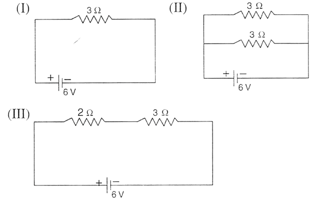
You are given three circuits. Identify the circuit with the minimum dissipation of heat.
Answer
For circuit (I) :
- Net Resistance (R) = 3 Ω
- Voltage (V) = 6 V
.......... (1)
For circuit (II) :
As resistances are in parallel combination and also have equal value then
So, net resistance (R) = Ω
Voltage (V) = 6V
Heat Dissipated = P = W .......... (2)
For circuit (III) :
As resistances are in series combination then
So, net resistance (R) = 5 Ω
Voltage (V) = 6V
Heat Dissipated = P = W .......... (3)
From (1), (2) and (3) it is clearly visible that in circuit (iii) heat dissipation is minimum.
Electrical power P is given by the expression P = (Q × V) ÷ time.
(a) What do the symbols Q and V represent?
(b) Express the power P in terms of current and resistance explaining the meaning of symbols used there in.
Answer
(a) In the expression,
Symbol Q represents charge and the symbol V represents voltage.
(b) The expression for power P in terms of current and resistance is:
where,
- I represents current and
- R represents resistance.
Name the S.I. unit of electrical energy. How is it related to Wh?
Answer
The S.I. unit of electrical energy is Joule.
The relation between Wh and Joule is as follows —
1 Wh = 3600 J
Explain the meaning of the statement 'the power of an appliance is 100 W'.
Answer
The statement 'the power of an appliance is 100 W' means that 100 J of electrical energy is consumed by the appliance in 1 second.
(i) State and define the household unit of electricity.
(ii) What is the voltage of the electricity that is generally supplied to a house?
(iii) What is consumed while using different electrical appliances, for which electricity bills are paid?
Answer
(i) The household unit of electricity is Kilowatt hour (kWh).
One kilowatt-hour (kWh) is the electrical energy consumed by an electrical appliance of power 1 kilowatt when it is used for 1 hour.
(ii) The voltage of the electricity that is generally supplied to a house is 220 volt.
(iii) The electrical energy is consumed by various appliances in our houses (or industries) and it's cost is paid to the electrical company.
Define the term kilowatt-hour and state its value in S.I. unit.
Answer
One kilowatt-hour (kwh) is the electrical energy consumed by an electrical appliance of power 1 kilowatt when it is used for 1 hour.
Value of kilowatt-hour (kWh) in S.I. unit is —
1 kWh = 3.6 × 10⁶ J
How do kilowatt and kilowatt-hour differ?
Answer
Kilowatt is the unit of electrical power. i.e., one kilowatt is the electric power consumed when a current of 1 ampere flows through a circuit having a potential difference of 1 volt.
Kilowatt-hour is the unit of electrical energy i.e., One kilowatt - hour (kwh) is the electrical energy consumed by an electrical appliance of power 1 kilowatt when it is used for 1 hour.
What do you mean by power rating of an electrical appliance? How do you use it to calculate (a) the resistance of the appliance, and (b) the safe limit of the current in it, while in use ?
Answer
An electrical appliance such as electric heater, geyser etc is rated with it's power and voltage.
For example, an electric bulb is rated as 100 W - 220 V. It means that if the bulb is lighted on a 220 V supply, the electric power consumed by it is 100 W (i.e., 100 J of electric energy is consumed by the bulb in 1 s).
(a) Resistance of element of appliance while in use is —
(b) The safe limit of current in it, while in use is —
If current exceeds this value, the power supplied at voltage V will exceed the rated power of the appliance and the appliance may get damaged. So this value of current is called the safe current which can flow through the appliance at voltage V.
An electric bulb is rated '100 W, 250 V'. What information does this convey ?
Answer
When an electric bulb is rated '100 W, 250 V' it means that if the bulb is lighted on a 250 V supply, the electric power consumed by it is 100 W (i.e., 100 J of electrical energy is consumed by the bulb in 1 s).
List the names of three electrical gadgets used in your house. Write their power, voltage rating and approximate time for which each one is used in a day. Hence find the electrical energy consumed by each in a month of 30 days.
Answer
| Appliance | Power (in kilowatt) | Voltage (V) | Time (t) | Electrical energy (E = P × t) in (kWh) |
|---|---|---|---|---|
| Fluorescent tube | 0.04 | 220 | 6 | 0.24 |
| Television set | 0.12 | 220 | 3 | 0.36 |
| Room heater | 1 | 220 | 2 | 2 |
(i) Energy consumed by fluorescent tube in one day = 0.24 kWh
Hence, energy consumed in 30 days = 0.24 x 30 = 7.2 kWh.
(ii) Energy consumed by television set in one day = 0.36 kWh
Hence, energy consumed in 30 days = 0.36 x 30 = 10.8 kWh.
(iii) Energy consumed by room heater in one day = 2 kWh
Hence, energy consumed in 30 days = 2 x 30 = 60 kWh.
Two lamps, one rated 220 V, 50 W and the other rated 220 V, 100 W, are connected in series with mains of voltage 220 V. Explain why does the 50 W lamp consume more power.
Answer
Resistance of lamp A (rating 220 V, 50 W) is —
Substituting the values in the formula above we get,
Resistance of lamp B (rating 220 V, 100 W) is —
Substituting the values in the formula above we get,
From formula, we get, P = I2 R
As we observe that RA > RB and same current is flowing in both the lamps as both are connected in series therefore PA > PB.
Hence, 50 W lamp consumes more power than 100 W lamp.
Name the factors on which the heat produced in a wire depends when current is passed in it, and state how does it depend on the factors stated by you.
Answer
The amount of heat produced in a wire on passing current through it, depends on the following three factors.
- The amount of current passing through the wire — The amount of heat H produced in a wire is directly proportional to the square of current I passing through the wire, i.e., H ∝ I2
- The resistance of wire — The amount of heat H produced in the wire is directly proportional to the resistance R of the wire, i.e., H ∝ R.
- The time for which current is passed in the wire — The amount of heat H produced in a wire is directly proportional to the time t for which current is passed in the wire i.e., H ∝ t
An electric bulb of resistance 500 Ω draws current 0.4 A from the source. Calculate : (a) the power of bulb and (b) the potential difference at its end.
Answer
(a) Given,
- Resistance (R) = 500 Ω
- Current (I) = 0.4 A
- Power = ?
From Ohm's law,
V = IR
Substituting the values in the formula above, we get,
V = 0.4 x 500 = 200 V
Power (P) = VI
Substituting the values in the power formula we get,
P = 200 x 0.4 = 80 W
Hence, the power of bulb = 80 W
(b) The potential difference at its end is 200 V.
A current of 3 A is passed through a coil of resistance 75 Ω for 2 minutes. (a) How much heat energy is produced? (b) How much charge is passed through the resistance ?
Answer
(a) Given,
- Current (I) = 3 A
- Resistance (R) = 75 Ω
- Time (t) = 2 min = 120 s
- Heat produced = ?
Using
H = I2Rt
Substituting the values in the formula above, we get,
H = 32 x 75 x 120 = 81000 J
Hence, heat energy produced = 81000 J
(b) Charge passed through the resistance = ?
From relation,
Q = It
Substituting the values in the formula above we get,
Q = 3 x 120 = 360 C
Hence, charge passed through the resistance = 360 C
Calculate the current through a 60 W lamp rated for 250 V. If the line voltage falls to 200 V, how is the power consumed by the lamp affected?
Answer
Given,
- Power (P) = 60 W
- Voltage (V) = 250 V
We know that,
Power (P) = VI
Substituting the values in the formula above, we get,
60 = 250 x I
⇒ I =
⇒ I = 0.24 A
So, current through the lamp = 0.24 A
Power consumed when voltage is 200 V = ?
Resistance of lamp (R) =
Substituting the values in the formula, we get,
From relation,
P =
Substituting the values in the formula, we get,
Hence, the power consumed reduces to 38.4 W.
An electric bulb is rated '100 W, 250 V'. How much current will the bulb draw if connected to a 250 V supply ?
Answer
Given,
- Power (P) = 100 W
- Voltage (V) = 250 V
From relation,
Power (P) = VI
Substituting the values in the formula above, we get,
100 = 250 x I
⇒ I =
⇒ I = 0.4 A
Hence, current drawn = 0.4 A
An electric bulb is rated '220 V, 100 W'. (a) What is its resistance? (b) What safe current can be passed through it?
Answer
(a) Given,
- P = 100 W
- V = 220 volt
We know that,
Power P =
Substituting the values in the formula above, we get,
Hence, resistance of electric bulb = 484 Ω
(b) From relation,
P = VI
Safe current (I) =
Substituting the value we get,
I =
⇒ I = 0.45 A
Hence, safe current limit = 0.45 A
A bulb of power 60 W is used for 12.5 h each day for 30 days. Calculate the electrical energy consumed.
Answer
Given,
- Power (P) = 60 W
- time (t) = 12.5 h for 30 days
As energy consumed is given by,
E = P × t
= 60 x 12.5
= 750 Wh
Therefore, the electrical energy consumed in one day is 750 Wh.
Electrical energy consumed in 30 days = 750 x 30 = 22500 Wh = 22.5 kWh
Hence, the electrical energy consumed in 30 days is 22.5 kWh.
An electric press is rated '750 W, 230 V'. Calculate the electrical energy consumed by the press in 16 hours.
Answer
Given,
- Power (P) = 750 W
- time (t) = 16 h
As energy consumed is given by,
E = P × t
= 750 x 16
= 12000 Wh
= 12 kWh
Hence, the electrical energy consumed in 16 hours is 12 kWh.
An electrical appliance having a resistance of 200 Ω is operated at 200 V. Calculate the energy consumed by the appliance in 5 minutes (i) in joule, (ii) in kWh.
Answer
(i) Given,
- Resistance (R) = 200 Ω
- Voltage (V) = 200 volt
- Time (t) = 5 min = 300 sec
As we know,
Substituting the values in the formula above we get,
= 60,000 J
Hence, energy consumed = 60,000 J
(ii) In kWh = ?
As we know,
1 kWh = 3.6 x 10⁶ J
⇒ 1 J = kWh
⇒ 60,000 J = kWh = 0.0167 kWh
Hence, energy consumed = 0.0167 kWh
A bulb rated 12 V, 24 W operates on a 12 volt battery for 20 minutes. Calculate —
(i) the current flowing through it, and
(ii) the energy consumed.
Answer
(i) Given,
- Voltage (V) = 12 V
- Power (P) = 24 W
- Current (I) = ?
From relation,
Power (P) = VI
Substituting the values in the formula above, we get,
24 = 12 x I
⇒ I =
⇒ I = 2 A
Hence, the current flowing through it is 2 A.
(ii) Energy (E) = P × t
- Time (t) = 20 min = 1200 sec
E = 24 x 1200 = 28,800 J
Hence, energy consumed = 28,800 J
A current of 0.2 A flows through a wire whose ends are at a potential difference of 20 V. Calculate —
(i) the resistance of the wire, and
(ii) the heat energy produced in 1 minute.
Answer
(i) Given,
- Current (I) = 0.2 A
- Potential difference (V) = 20 V
From Ohm's law
V = IR
Substituting the values in the formula above, we get,
20 = 0.2 x R
⇒ R = = 100 Ω
Hence, the resistance of the wire = 100 Ω
(ii) Given,
- Time (t) = 60 sec
- heat energy produced in 1 minute = ?
From relation,
Heat energy (H) = I2Rt
Substituting the values in the formula above, we get,
H = 0.22 x 100 x 60 = 240 J
Hence, the heat energy produced in 1 minute is 240 joules.
What is the resistance, under normal working conditions, of an electric lamp rated '240 V, 60 W'? If two such lamps are connected in series across a 240 V mains supply, explain why each one appears less bright.
Answer
Given,
- Voltage (V) = 240 V
- Power (P) = 60 W
- Resistance (R) = ?
From relation
We get,
So, resistance of the electric lamp = 960 Ω
From the relation for current through the element, we know,
Substituting the values in the formula above, we get,
When one lamp is connected across the mains, it draws 0.25 A current. If two such lamps are connected in series across the mains, current through each bulb becomes —
i.e., current is halved.
Hence, heating (= I2Rt) in each bulb becomes one fourth, so each bulb appears less bright.
Two bulbs are rated '60 W, 220 V' and '60 W, 110 V' respectively. Calculate the ratio of their resistances.
Answer
Given,
- Voltage (V1) = 220 V
- Voltage (V2) = 110 V
- P = 60 W (both bulbs have same power)
- Resistance (R) = ?
From relation
Case 1 :
Case 2 :
Ratio between the two is —
Hence, the ratio of resistances of the two bulbs is 4 : 1.
An electric bulb is rated '250 W, 230 V'. Calculate :
(i) the energy consumed in one hour, and
(ii) the time in which the bulb will consume 1.0 kWh energy when connected to 230 V mains?
Answer
(i) Given,
- Power (P) = 250 W
- Voltage (V) = 230 V
- Time (t) = 1 h = 3600 sec
- Energy (E) = ?
From relation,
E = P × t
Substituting the values in the formula above, we get,
E = 250 x 3600 = 9 x 10⁵ J
Hence, energy consumed in one hour = 9 x 10⁵ J
(ii) Let t be the time in which the bulb will consume 1.0 kWh energy when connected to 230 V mains.
P = 1.0 kWh = 1000 Wh
Substituting the value in the formula, we get,
1000 = 250 x t
⇒ t = = 4 h
Hence, time = 4 h
Three heaters each rated '250 W, 100 V' are connected in parallel to a 100 V supply.
Calculate —
(i) the total current taken from the supply,
(ii) the resistance of each heater, and
(iii) the energy supplied in kWh to the three heaters in 5 hours.
Answer
(i) Given,
- Power (P) = 250 W
- Voltage (V) = 100 V
- Current through each heater (I) = ?
As
P = VI
Substituting the values in the formula above we get,
250 = 100 x I
⇒ I = 250 / 100 = 2.5 A
So, current through each heater = 2.5 A
And
Current for three heaters = 3 x 2.5 = 7.5 A
Hence, total current taken from supply = 7.5 A
(ii) Resistance for each heater (R) = ?
Since,
V = IR
Substituting the values in the formula above we get,
100 = 2.5 x R
⇒ R = = 40 Ω
Hence, resistance of each heater = 40 Ω
(iii) Energy supplied to three heater in 5 h = ?
Energy (E) = P × t
Substituting the values in the formula above, we get,
E = 250 x 5 = 1250 Wh = 1.25 kWh
Now,
Energy for three heaters = 3 × 1.25 = 3.75 kWh
Hence, energy supplied to the three heaters = 3.75 kWh
A bulb is connected to a battery of p.d. 4 V and internal resistance 2.5 ohm. A steady current of 0.5 A flows through the circuit. Calculate —
(i) the total energy supplied by the battery in 10 minutes,
(ii) the resistance of the bulb, and
(iii) the energy dissipated in the bulb in 10 minutes.
Answer
(i) Given,
- Voltage (V) = 4 V
- Internal resistance = 2.5 Ω
- Current (I) = 0.5 A
- time (t) = 10 min = 600 sec
Energy supplied by the battery (E) = V x I x t
Substituting the values in the formula, we get,
E = 4 x 0.5 x 600 = 1200 J
Hence, total energy supplied = 1200 J
(ii) Resistance of the bulb = ?
From relation,
V = I (R + r)
We get,
4 = 0.5 (R + 2.5)
⇒ 4 = (0.5 R) + (0.5 x 2.5)
⇒ 4 = (0.5 R) + 1.25
⇒ 0.5R = 4 - 1.25
⇒ R = = 5.5 Ω
Hence, resistance of the bulb = 5.5 Ω
(iii) Energy dissipated in the bulb in 10 min = ?
From relation
E = I2Rt
Substituting the values in the formula above, we get,
E = 0.5 x 0.5 x 5.5 x 600 = 825 J
Hence, energy dissipated = 825 J
Two resistors A and B of resistance 4 Ω and 6 Ω respectively are connected in parallel. The combination is connected across a 6 volt battery of negligible resistance. Calculate : (i) the power supplied by the battery, and (ii) the power dissipated in each resistor.
Answer
(i) Given,
- Resistance, RA = 4 Ω
- Resistance, RB = 6 Ω
Let equivalent resistance of the two resistors connected in parallel be RP
Thus, equivalent resistance = 2.4 Ω
From relation
We get,
Hence, power supplied = 15 W
(ii) Power dissipation across each resistor = ?
From relation,
P = VI
Current across A (4 Ω) resistor —
IA = = 1.5 A
Power dissipation across A = VIA
Substituting we get,
P = 6 x 1.5 = 9 W
Similarly,
Current across B (6 Ω) resistor —
IB = = 1 A
Power dissipation across B resistor = VIB
Substituting the values in the formula above, we get,
P = 6 x 1 = 6 W
Hence, the power dissipated across A is 9 W and across B is 6 W.
A battery of e.m.f. 15 V and internal resistance 2 Ω is connected to two resistors of resistances 4 Ω and 6 Ω joined in series. Find the electrical energy spent per minute in 6 Ω resistor.
Answer
(i) Given,
- e.m.f. (V) = 15 V
- r = 2 Ω
- R1 = 4 Ω
- R2 = 6 Ω
Electrical energy = ?
As the battery and resistors are connected in series, equivalent resistance is given by
R = 2 + 4 + 6 = 12 Ω
From Ohm's law —
V = IR
Substituting the values in the formula above, we get,
15 = I x 12
⇒ I = = 1.25 A
So, current in circuit = 1.25 A
Now,
Voltage across 6 Ω = IR = 1.25 × 6 = 7.50 V
Voltage across 6 Ω = 7.5 V
Time (t) = 1 min = 60 sec
We know,
Substituting the values in the formula above, we get,
E =
= 7.52 x 10
= 562.5 J
Hence, energy spent across the 6 Ω resistor = 562.5 J
Water in an electric kettle connected to a 220 V supply takes 5 minutes to reach its boiling point. How long will it take if the supply voltage falls to 200 V?
Answer
Given,
- V = 220 V
- time (t) = 5 min = 300 sec
From relation
and
Heat produced (H) —
H = P x t
⇒ H = x t
Case 1 : For V = 220 V
Case 2 : For V = 200 V
Equating 1 and 2 we get,
Hence, time taken = 6.05 min
An electric toaster draws current 8 A in a circuit with source of voltage 220 V. It is used for 2 h. Find the cost of operating the toaster if the cost of electrical energy is ₹4.50 per kWh.
Answer
Given,
- I = 8 A
- V = 220 V
- t = 2 h
- Rate of electricity = 4.50 per kWh
- Cost = ?
From relation,
E = V x I x t
we get,
E = 220 x 8 x 2 = 3520 Wh = 3.52 kWH
As cost of energy for 1 kWh = ₹ 4.50
Therefore, cost of energy for 3.52 kWh = 4.5 x 3.52 = ₹15.84
Hence, cost of electrical energy = ₹15.84
An electric iron is rated 220 V, 2 kW. If the iron is used for 3h daily find the cost of running it for 1 week if it costs ₹ 4.25 per kWh.
Answer
Given,
- Power (P) = 2 kW
- Voltage (V) = 220 V
- Time (t) = 7 x 3 = 21 h
From relation,
E = P × t
Substituting the values in the formula above, we get,
E = 2 x 21 = 42 kWh
Cost for 1 kWh of energy = ₹ 4.25
∴ Cost for 42 kWh of energy = 4.25 x 42 = ₹ 178.50
A geyser is rated '1500 W, 250 V'. This geyser is connected to 250 V mains. Calculate —
(i) the current drawn,
(ii) the energy consumed in 50 hours, and
(iii) the cost of energy consumed at ₹ 4.20 per kWh.
Answer
(i) Given,
- P = 1500 W
- V = 250 volt
Current drawn (I) =
Substituting the values in the formula, we get,
I =
⇒ I = 6 A
Hence, current drawn = 6 A
(ii) energy consumed in 50 hours = ?
- t = 50 h
From relation,
E = P × t
Substituting the values in the formula above, we get,
E = 1500 x 50 = 75000 Wh = 75 kWh
Hence, energy consumed in 50 hours = 75 kWh
(iii) cost of energy consumed at ₹ 4.20 per kWh = ?
- Cost per unit of energy = ₹ 4.20
Cost for 75 kWh of energy = 4.2 x 7.5 = ₹ 315
Hence, cost of energy consumed = ₹ 315