
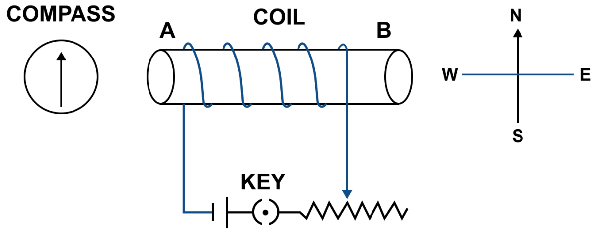
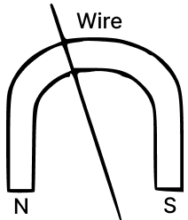
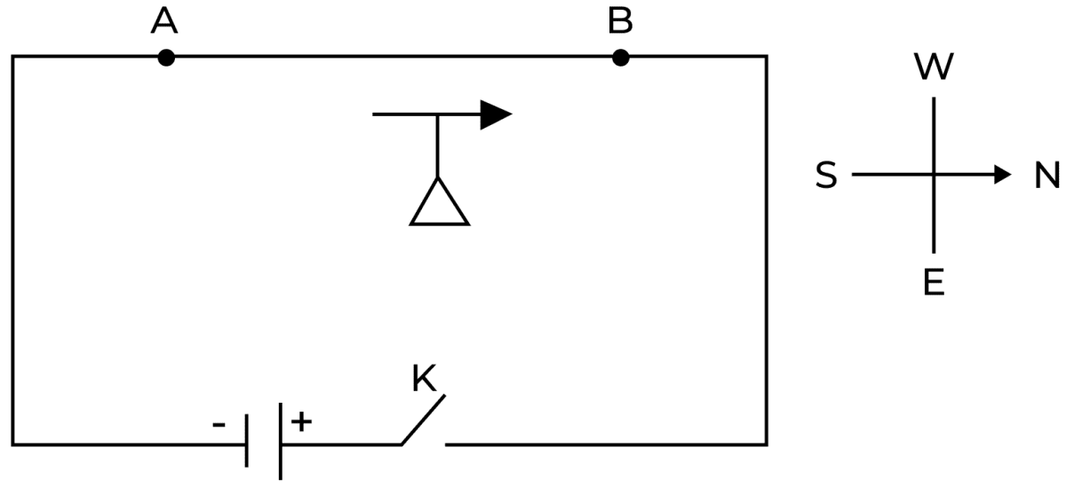
In the figure given below, when the key is pressed, a current passes in the wire in the direction from A to B (i.e., from south to north). The north pole of the compass needle will deflect towards:
- East
- North
- South
- West

Answer
West
Reason — When a current passes through a wire from south to north (A to B), it generates a magnetic field around the wire. According to the right-hand rule for electromagnetism, if you wrap your right-hand fingers around the wire in the direction of the current, your thumb will point in the direction of the magnetic field.
So, with the current flowing from A to B, if you curl your fingers around the wire, your thumb would point towards the west. This indicates that the magnetic field is directed towards the west.
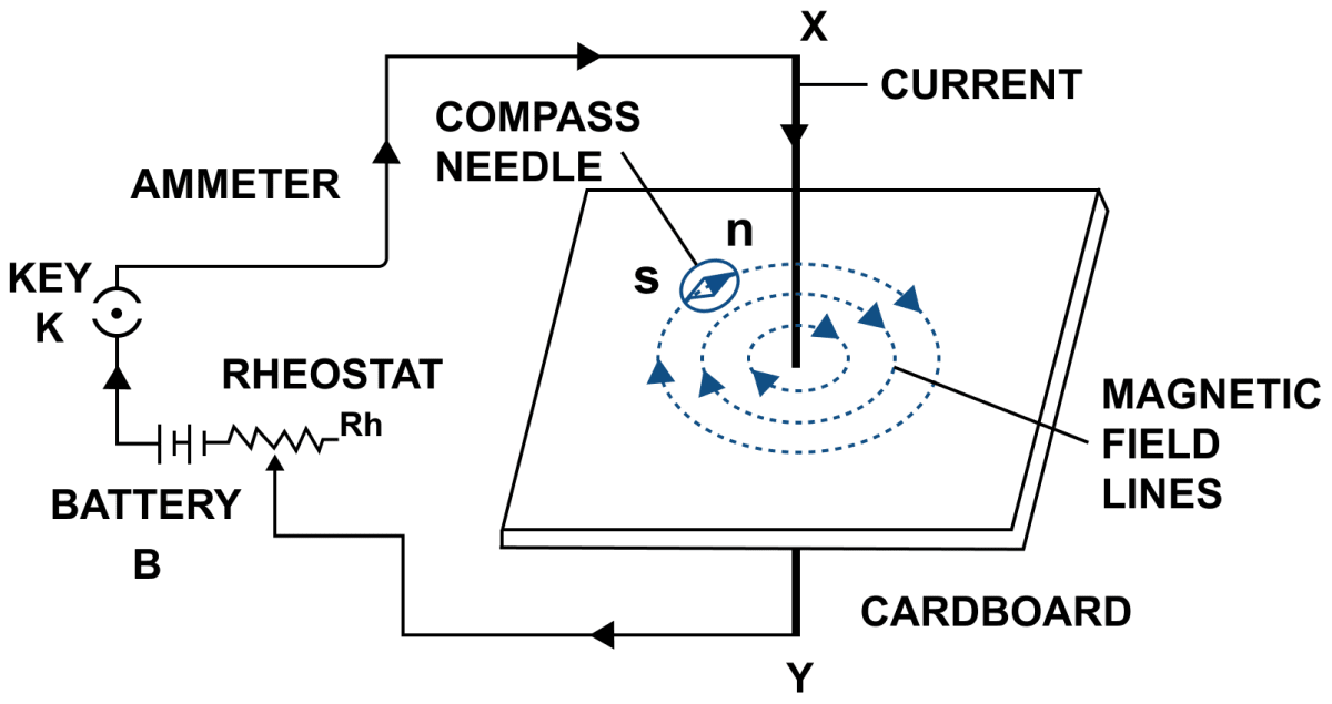
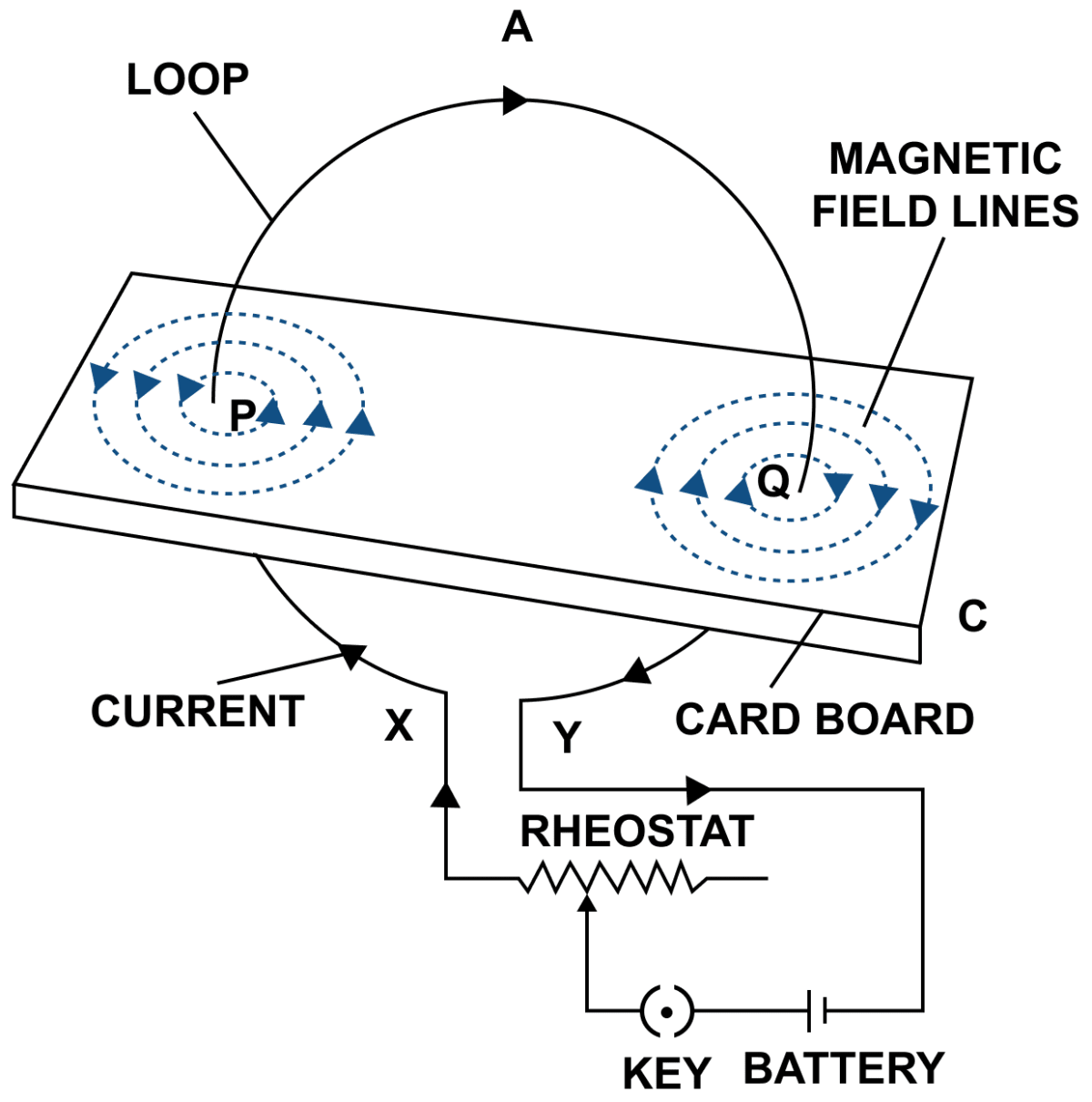
In the figure given below, current is passed in a downward direction through a cardboard. The magnetic field lines would be :

- straight lines
- concentric circles
- elliptical lines
- squares
Answer
concentric circles
Reason — According to the right hand thumb rule, with current passing downward through the cardboard, if we imagine wrapping our right hand around the wire with our fingers pointing downwards, our thumb will point in the direction of the magnetic field lines.
Hence, magnetic field lines would form concentric circles around the wire.
According to the right hand thumb rule, the thumb points in the direction of ............... and fingers encircle the wire in direction of ............... .
- magnetic field lines, current
- electric field lines, current
- current, magnetic field lines
- none of the above
Answer
current, magnetic field lines
Reason — According to the right hand thumb rule, the thumb points in the direction of current and fingers encircle the wire in direction of magnetic field lines.
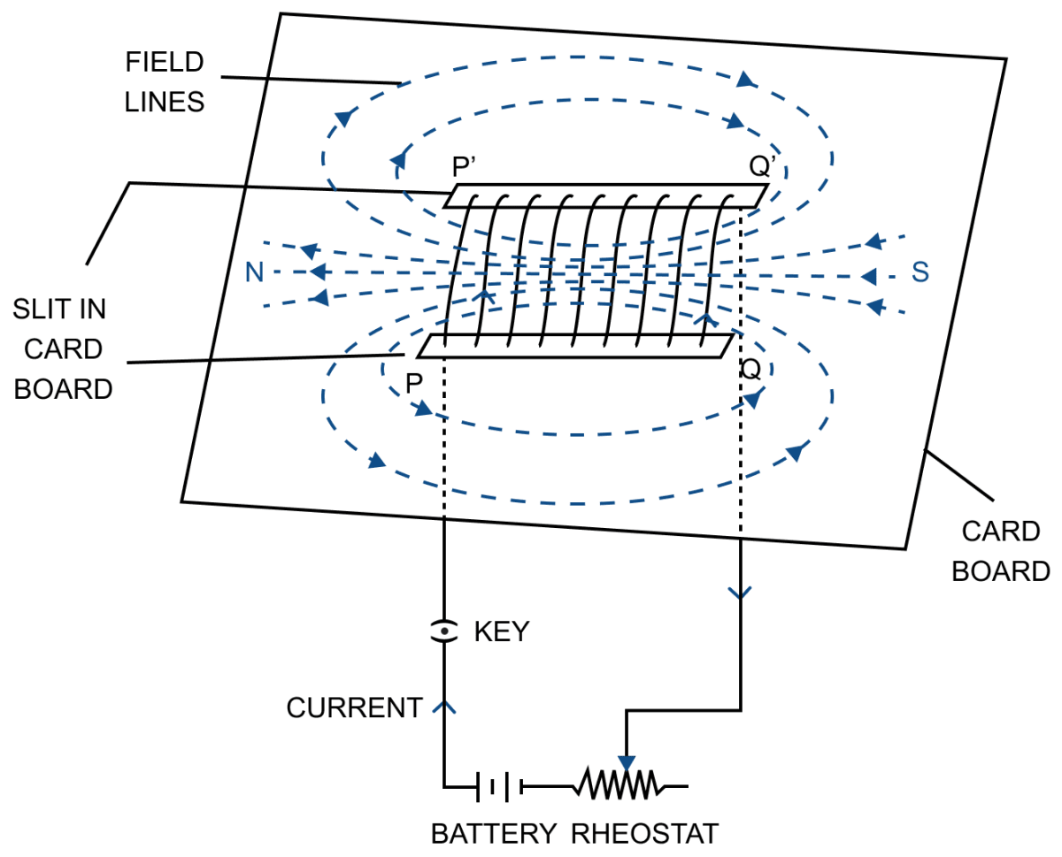
In the figure given below, the direction of current in the loop is ............... . So, it behaves as a ............... .
- anticlockwise, south pole
- anticlockwise, north pole
- clockwise, north pole
- clockwise, south pole

Answer
anticlockwise, north pole
Reason — In the figure given above, the direction of current in the loop is anticlockwise. So, it behaves as a north pole .
Which of the following statements is not true ?
- The strength of magnetic field due to a bar magnet can be changed.
- A solenoid behaves like a bar magnet i.e. it attracts iron filings.
- The magnetic field increases if a soft iron core is placed along the axis of solenoid.
- The magnetic field lines inside the solenoid are nearly straight and parallel to the axis of solenoid.
Answer
The strength of magnetic field due to a bar magnet can be changed.
Reason — The strength of magnetic field due to a bar magnet cannot be changed.
Which of the following statements is not true for an electromagnet ?
- It is made of soft iron.
- Its magnetic field strength can be changed.
- The polarity of an electromagnet cannot be changed.
- It can easily be demagnetised.
Answer
The polarity of an electromagnet cannot be changed.
Reason — The polarity of an electromagnet can be reversed by reversing the direction of current in its solenoid.
The magnetic field lines inside a solenoid are :
- parallel and circular
- straight and parallel to the axis of solenoid
- straight and perpendicular to the axis of solenoid
- circular
Answer
straight and parallel to the axis of solenoid
Reason — The magnetic field lines inside a solenoid are straight and parallel to the axis of solenoid.
On reversing the direction of current in a wire, the magnetic field produced by it:
- gets reversed in direction
- increases in strength
- decreases in strength
- remains unchanged in strength and direction
Answer
gets reversed in direction
Reason — By reversing the direction of current in a wire, the magnetic field produced by it gets reversed in direction because the polarity of the faces of the wire gets reversed.
Horse shoe magnets are used in :
- d.c. motor
- a.c. generator
- electric bell
- all of the above
Answer
all of the above
Reason — Horse shoe magnets are used in :
- d.c. motor
- a.c. generator
- electric bell
Two infinitely long parallel wires carry equal currents in the same direction. The magnetic field at the mid-point in between the two wires is :
- Twice the magnetic field produced due to each of the wire.
- Half of the magnetic field produced due to each of the wire.
- Zero
- Square of the magnetic field produced by each wire.
Answer
Zero
Reason — When two infinitely long parallel wires carry equal currents in the same direction, each wire produces a magnetic field around it according to the right-hand thumb rule.
At the mid-point between the wires, the magnetic field due to one wire is equal in magnitude but opposite in direction to that due to the other wire.
Since these fields act in opposite directions, they cancel each other exactly, resulting in a net magnetic field of zero at the midpoint.
Hence, the magnetic field at the mid-point in between the two wires is zero.
How is magnetic field due to a straight current carrying wire affected if current in wire is (a) decreased, (b) reversed?
Answer
(a) On decreasing current in the wire, the deflection of compass needle decreases which implies that the strength of magnetic field around the wire decreases.
(b) On reversing the direction of current the magnetic needle of compass reverses because the direction of magnetic field reverses.
A student draws three magnetic field lines 1, 2, 3 of a bar magnet with the help of a compass needle. Are all the lines of force correctly drawn? Give reason for your answer.
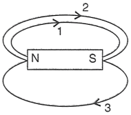
Answer
No, the field line labelled 3 is incorrect and 1, 2 are correct because Magnetic field lines must start from the North pole and end at the South pole outside the magnet but line 3 is shown going from S to N outside the magnet, which is wrong.
The diagram given below shows magnetic field pattern around a bar magnet. Identify the poles A and B.
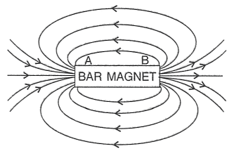
Answer
As, magnetic field lines go from North to South pole outside a magnet and here the lines are coming out from pole B and entering into pole A.
So, A = South Pole and B = North Pole
The diagrams given below show some magnetic field patterns.
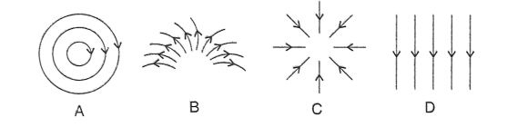
Answer the following questions :
(a) Which pattern shows uniform magnetic field lines?
(b) Which pattern is for a straight current carrying wire?
(c) Which pattern is depicted by current in a loop?
Answer
(a) Pattern D
Reason — Pattern D shows uniform magnetic field lines because it contains parallel, equally spaced straight lines indicating a uniform magnetic field.
(b) Pattern A
Reason — The pattern for the magnetic field around a straight current carrying wire is concentric circles around it which is shown in pattern A. So, A shows pattern of magnetic field for a straight current carrying wire.
(c) Pattern B
Reason — In pattern B, magnetic field lines are emerging from the loop and curving which is equivalent to a circular current carrying loop. So, B shows pattern depicted by current in a loop.
A straight wire lying in a horizontal plane carries a current from north to south. (a) What will be the direction of magnetic field at a point just underneath it? (b) Name the law used to arrive at the answer in part (a).
Answer
(a) When a straight wire is lying in a horizontal plane and carrying current from north to south then the direction of magnetic field at a point just underneath is towards east.
(b) The law used is right hand thumb rule.
A wire, bent into a circle, carries a current in an anticlockwise direction. What polarity does this face of the coil exhibit?
Answer
This face of the coil exhibits North polarity.
What is the direction of magnetic field at the centre of a coil carrying current in (i) the clockwise, (ii) the anticlockwise direction?
Answer
(i) The direction of magnetic field at the centre of coil carrying current in clockwise direction is along the axis of coil inwards.
(ii) The direction of magnetic field at the centre of coil carrying current in anticlockwise direction is along the axis of coil outwards.
How is the magnetic field due to a solenoid carrying current affected if a soft iron bar is introduced inside the solenoid?
Answer
When a soft iron is introduced inside a solenoid, then the strength of magnetic field increases.
Name one device that uses an electromagnet.
Answer
An electric bell is one of the common devices that uses an electromagnet.
Complete the following sentences:
(a) When current flows in a wire, it creates ............... .
(b) On reserving the direction of current in a wire, the magnetic field produced by it gets ............... .
(c) A current carrying solenoid behaves like a ............... .
(d) A current carrying solenoid when freely suspended, it always rests in ............... direction.
Answer
(a) When current flows in a wire, it creates magnetic field around it.
(b) On reserving the direction of current in a wire, the magnetic field produced by it gets reversed.
(c) A current carrying solenoid behaves like a bar magnet.
(d) A current carrying solenoid when freely suspended, it always rest in north-south direction.
State a law, which determines the direction of magnetic field around a current carrying wire.
Answer
Right hand thumb rule is used to determine the direction of magnetic field around a current carrying wire.
Right hand thumb rule — If we hold the current carrying conductor in our right hand such that the thumb points in the direction of flow of current, then the fingers encircle the wire in the direction of the magnetic field lines.
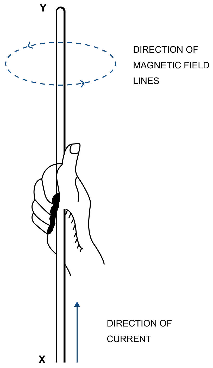
In figure, the direction of current in the conductor XY is upwards (i.e., X to Y). The magnetic field lines are anticlockwise around the conductor.
What will happen to a compass needle when the compass is placed below a wire with needle parallel to it and a current is made to flow through the wire? Give a reason to justify your answer.
Answer
When current flows through the wire, a magnetic field is produced around it. Since the compass needle is placed just below the wire and initially parallel to it, the magnetic field at that point is perpendicular to the wire as given by the right-hand thumb rule.
Due to this magnetic field, the compass needle experiences a torque and deflects from its original position, aligning itself along the direction of the resultant magnetic field.
Name and state the rule by which the polarity at the ends of a current carrying solenoid is determined.
Answer
Polarity at the ends of a current carrying solenoid is determined by the Clock rule.
It states that looking at the face of the loop, if the current in wire around that face is in anticlockwise direction, the face has the north polarity, while if the current at that face is in clockwise direction, the face has the south polarity.
The diagram in below figure shows a small magnet placed near a solenoid AB with its north pole N near the end A. Current is switched on in the solenoid by pressing the key K.
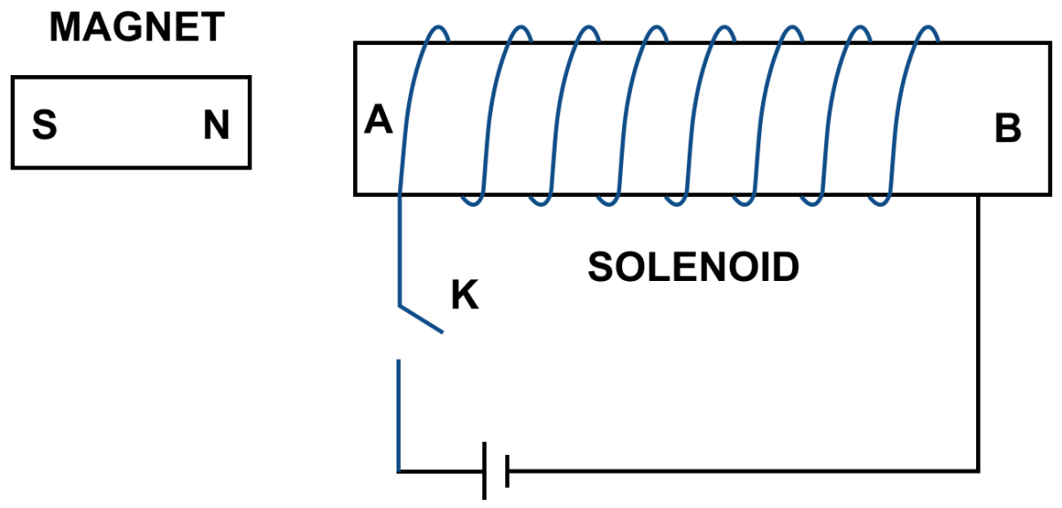
(a) State the polarity at the ends A and B.
(b) Will the magnet be attracted or repelled? Give a reason for your answer.
Answer
(a) The direction of current in the solenoid at the face A is anticlockwise, so it will have the North polarity and the face B of solenoid at which the current is clockwise will have the South polarity.
(b) The magnet will be repelled because the end A of the solenoid becomes North pole as current at this face is anticlockwise and it repels the north pole of the magnet.
State two ways by which the magnetic field due to a current carrying solenoid can be made stronger.
Answer
The magnetic field due to a current carrying solenoid can be made stronger —
- By increasing the number of turns of winding in the solenoid
- By increasing the current through the solenoid.
A magnet kept at the centre of two coils A and B is moved to and fro as shown in the diagram given below. The two galvanometers show deflection.
![A magnet kept at the centre of two coils A and B is moved to and fro as shown in the diagram. The two galvanometers show deflection. State with a reason whether x > y or x < y [x and y are magnitudes of deflection]. ICSE 2019 Physics Solved Question Paper.](https://cdn1.knowledgeboat.com/img/abp10/5/icse-2019-physics-question-paper-solved-4c-1200x271.png)
State with a reason whether : x > y or x < y.
Answer
x < y
Since, the coil A has less number of turns, therefore the e.m.f. generated in this coil will be less, hence the galvanometer x connected to this coil shows less deflection i.e., x < y.
Why does a current carrying freely suspended solenoid rest along a particular direction? State the direction in which it rests.
Answer
A current carrying solenoid behaves like a bar magnet so it rests itself in geographic North-South direction.
What effect will there be on a magnetic compass when it is brought near a current carrying solenoid?
Answer
The needle of the compass will rest in the direction of magnetic field due to solenoid at that point.
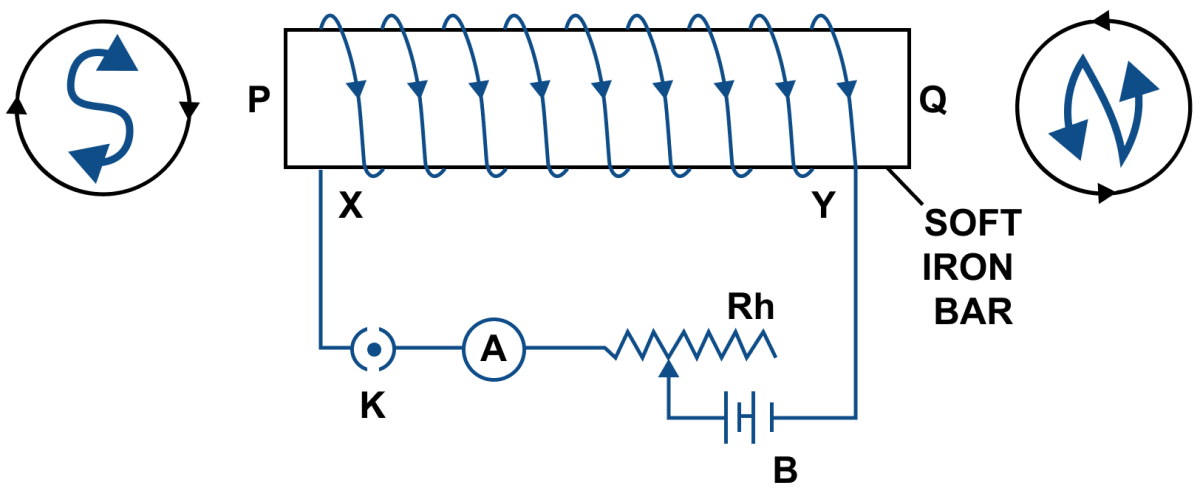
The diagram in below figure shows a coil wound around a soft iron bar XY. (a) State the polarity at the ends X and Y as the switch is pressed. (b) Suggest one way of increasing the strength of electromagnet so formed.
Answer
(a) When current is passed through the winding of the solenoid, current at end X is in anticlockwise direction so it becomes the North pole. The current at end Y is in clockwise direction so it becomes the South pole.
(b) One way of increasing the strength of electromagnet so formed is by reducing resistance of circuit by means of rheostat to increase current in the coil.
What is an electromagnet? Name two factors on which the strength of magnetic field of an electromagnet depends and state how does it depend on the factors stated by you.
Answer
An electromagnet is a temporary strong magnet made by passing current in a coil wound around a piece of soft iron. It is an artificial magnet.
The strength of magnetic field of an electromagnet depends on —
- Number of turns — By increasing the number of turns of windings in the solenoid, the strength of magnetic field of an electromagnet can be increased.
- Current — By increasing the current through the solenoid, the strength of magnetic field can be increased.
State two ways by which the strength of an electromagnet can be increased.
Answer
The strength of an electromagnet can be increased:
- By increasing the number of turns of winding in the solenoid.
- By increasing the current through the solenoid.
State two advantages of an electromagnet over a permanent magnet.
Answer
An electromagnet has the following advantages over an electromagnet —
- An electromagnet can produce a strong magnetic field.
- The strength of the magnetic field of an electromagnet can easily be changed by changing the current (or the number of turns) in the solenoid.
State two differences between an electromagnet and a permanent magnet.
Answer
Comparison of an electromagnet with a permanent magnet
| Electromagnet | Permanent magnet |
|---|---|
| It is made up of soft iron. | It is made up of steel. |
| It produces the magnetic field as long as current flows in it's coil. i.e., it produces the temporary magnetic field. | It produces a permanent magnetic field. |
Why is soft iron used as the core of the electromagnet in an electric bell?
Answer
The soft iron bar is used as the core of the electromagnet in an electric bell because it has low retentivity and therefore, the bar remains magnetized so long the electric current flows through the solenoid, but it gets demagnetized as soon as the current is switched off.
How is the working of an electric bell affected, if alternating current be used instead of direct current?
Answer
If an a.c. source is used in place of battery, the core of electromagnet will get magnetized, but the polarity at it's ends will change. Since attraction of armature does not depend on the polarity of electromagnet, so the bell will still ring on pressing the switch.
Name the material used for making the armature of an electric bell. Give a reason for your answer.
Answer
The material used for making the armature of an electric bell is soft iron.
It is used as the core of the electromagnet in an electric bell because it has low retentivity and therefore, the bar remains magnetized so long as the electric current flows through the solenoid but it gets demagnetized as soon as the current is switched off.
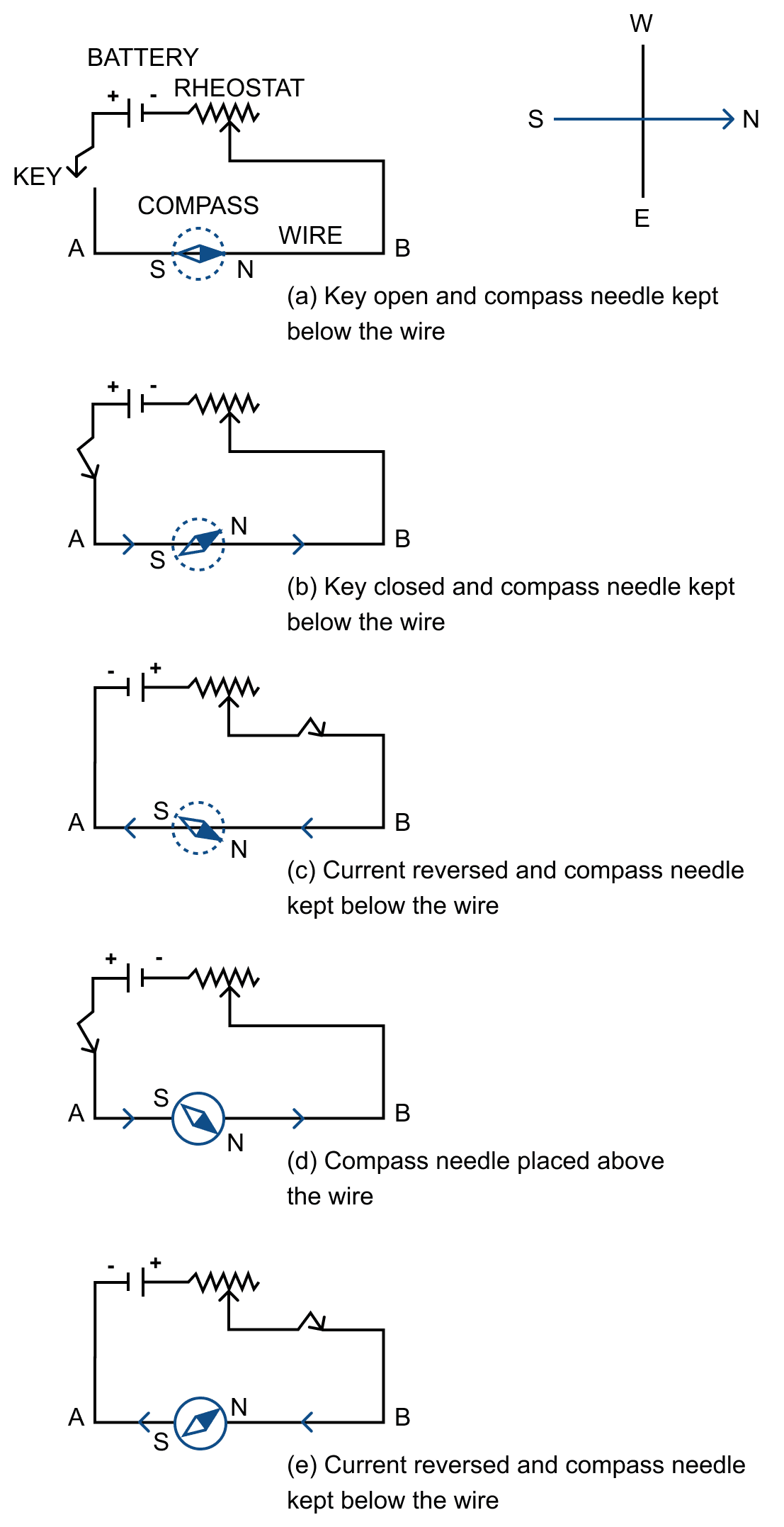
By using a compass needle describe how can you demonstrate that there is a magnetic field around a current carrying conductor.
Answer
Experiment:
In figure below, AB is a wire lying in the north-south direction and connected to a battery through a rheostat and a tapping key. A compass needle is placed just below the wire.
Observation —
(1) When the key is open i.e., no current passes through the wire, the needle points in the N-S direction (i.e., along the earth's magnetic field) with the north pole of needle pointing towards the north direction. In this position, the needle is parallel to the wire as shown in Fig. (a).
(2) When the key is pressed, a current passes in the wire in the direction from A to B (i.e. from south to north) and the north pole (N) of the needle deflects towards the west [Fig.(b)].
(3) When the direction of current in the wire is reversed by reversing the connections at the terminals of the battery, north pole (N) of the needle deflects towards the east [Fig.(c)].
(4) If the compass needle is placed just above the wire, the north pole (N) deflects towards east when the direction of current in wire is from A to B [Fig. (d)], but the needle deflects towards west as in figure (e), if the direction of current in wire is from B to A.
Through the experiment we can say that, when electric current is passed through a conducting wire, a magnetic field is produced around it.
Draw a diagram showing the direction of three magnetic field lines due to a straight wire carrying a current. Also show the direction of current in the wire.
Answer
Below diagram shows the direction of three magnetic field lines due to a straight wire carrying current:
The current in the wire is in clockwise direction.
Draw a labelled diagram showing the three magnetic field lines of a loop carrying current. Mark the direction of current and the direction of magnetic field by arrows in your diagram.
Answer
Below diagram shows the magnetic field lines of a loop carrying current:
Draw a diagram to represent the magnetic field lines along the axis of a current carrying solenoid. Mark arrows to show the direction of current in the solenoid and the direction of magnetic field lines.
Answer
Below diagrams shows the magnetic field lines along the axis of a current carrying solenoid with the direction of current and direction of magnetic field lines marked:
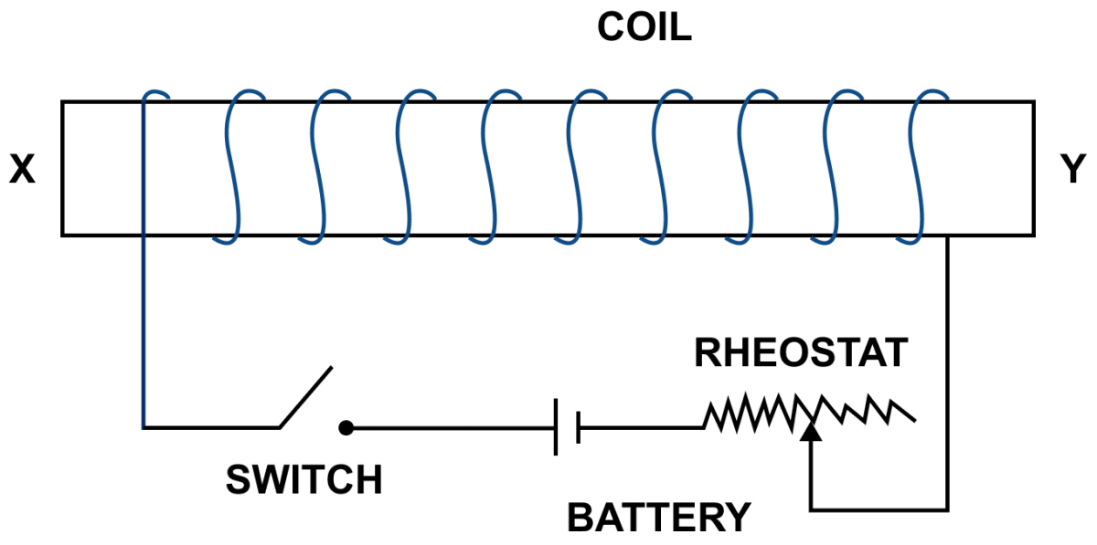
The diagram in below figure shows a spiral coil wound on a hollow cardboard tube AB. A magnetic compass is placed close to it. Current is switched on by closing the key.
(a) What will be the polarity at the ends A and B?
(b) How will the compass needle be affected? Give reason.
Answer
(a) With the help of the Right hand thumb rule, we get the polarity at A — North pole and at B — South pole.
(b) The end A of the coil behaves like north pole and repels north pole of compass needle. Hence, the compass needle deflects towards west.
You are required to make an electromagnet from a soft iron bar by using a cell, an insulated coil of copper wire and a switch. (a) Draw a circuit diagram to represent the process. (b) Label the poles of the electromagnet.
Answer
Below circuit diagram shows an electromagnet made from a soft iron bar by using a cell, an insulated coil of copper and a switch with its poles labelled:
(a) What name is given to a cylindrical coil of diameter less than its length?
(b) If a piece of soft iron is placed inside the coil mentioned in part (a) and current is passed in the coil from a battery, what name is then given to the device so obtained?
(c) Give one use of the device mentioned in part (b).
Answer
(a) Solenoid is a cylindrical coil of diameter less than its length.
(b) The device so obtained is an electromagnet.
(c) It is used in an electric relay.
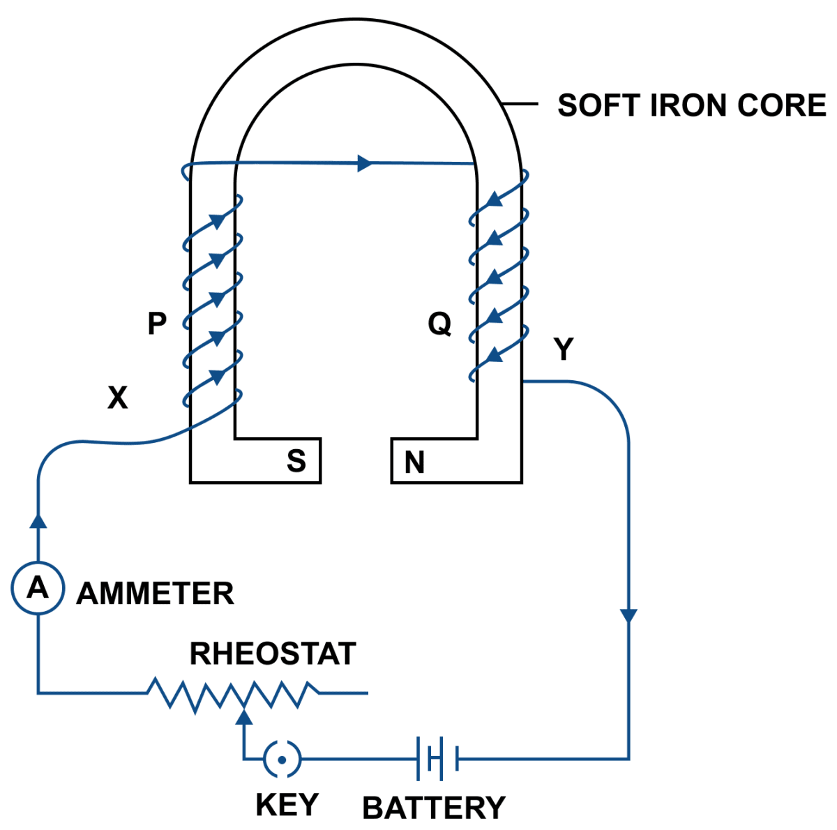
Show with the aid of the diagram how a wire is wound on a U-shaped piece of soft iron in order to make it an electromagnet. Complete the circuit diagram and label the poles of the electromagnet.
Answer
Below circuit diagram shows an electromagnet made by winding a wire on a U-shaped piece of soft iron:
Below figure shows the current flowing in the coil of wire wound around the soft iron horse shoe core.
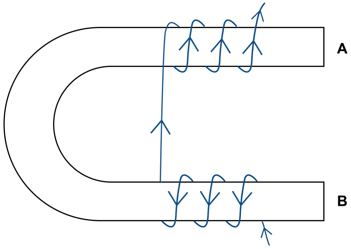
(a) State the polarities developed at the ends A and B.
(b) How will the polarity at the ends A and B change on reversing the direction of current.
(c) Suggest one way to increase the strength of the magnetic fieled produced.
Answer
(a) When current is passed through the windings, the end A of the arm becomes south pole (current at this face is clockwise) and the end B becomes north pole (current at this face is in anticlockwise direction).
(b) When the direction of current is reversed then the polarity will also reverse. A will become north pole (current at this face is in anticlockwise direction) and B will become south pole (current at this face is clockwise).
(c) The strength of magnetic field produced can be increased by increasing the current.
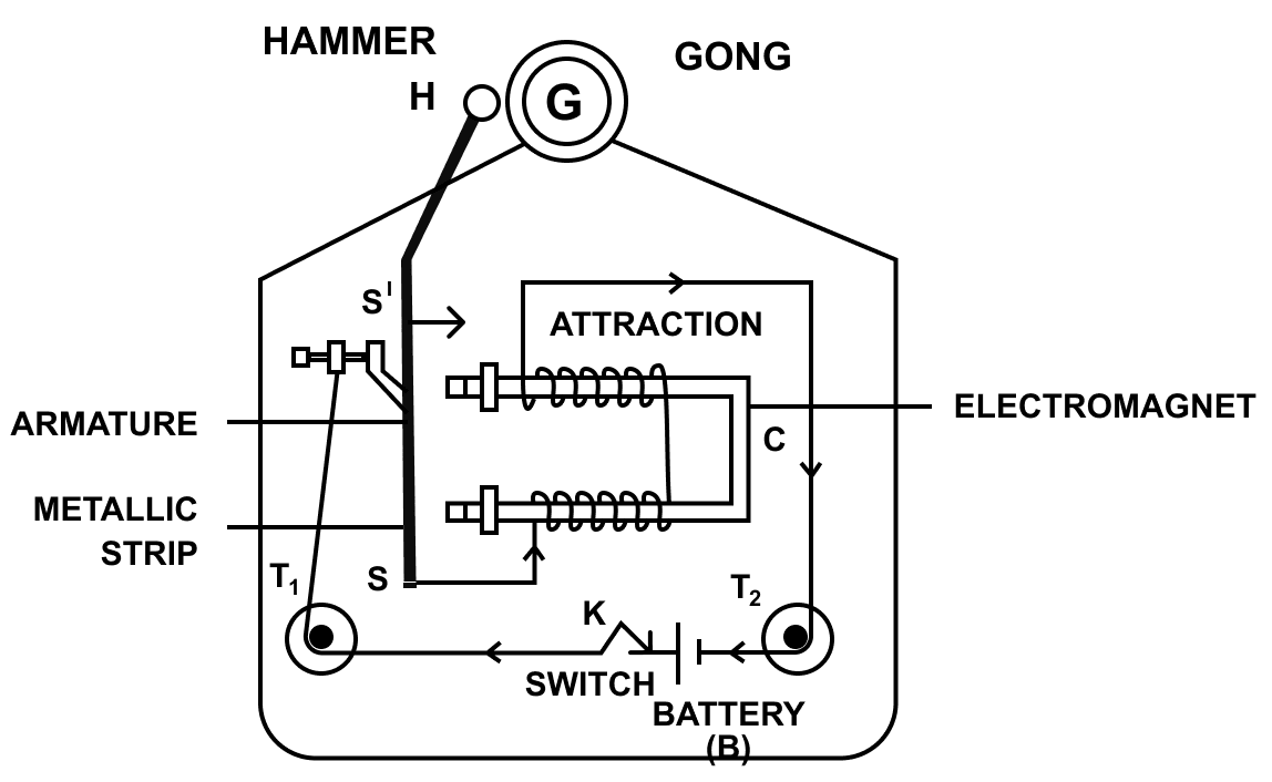
The incomplete diagram of an electric bell is given in below figure. Draw winding of coil on the core and complete the electric circuit in the diagram.
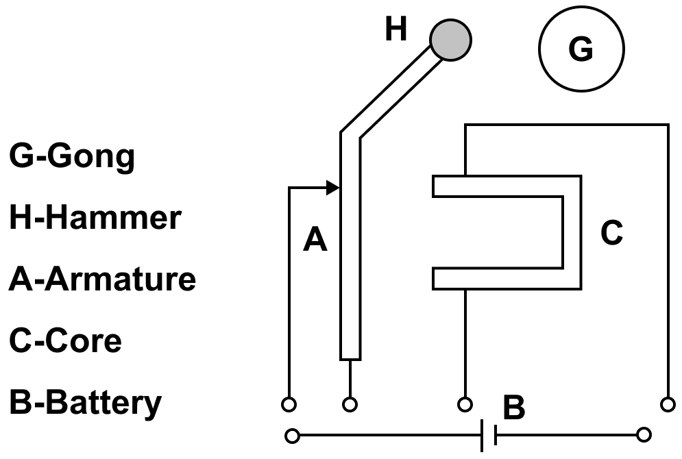
Answer
The completed diagram of the electric bell with winding of coil drawn is shown below:
A charge moving in a magnetic field in a direction other than the direction of the magnetic field experiences a force called :
- Lorentz force
- Nuclear force
- Electric force
- Gravitational force
Answer
Lorentz force
Reason — Lorentz, found that a charge moving in a magnetic field in a direction other than the direction of the magnetic field experiences a force called Lorentz force.
The magnitude of force acting on a current carrying wire placed in a magnetic field in a direction perpendicular to its length depends on :
- The current flowing in the wire
- The strength of the magnetic field
- The length of the wire
- all of the above
Answer
all of the above
Reason — The magnitude of force acting on a current carrying wire placed in a magnetic field in a direction perpendicular to its length depends on :
- The current flowing in the wire
- The strength of the magnetic field
- The length of the wire.
The speed of rotation of coil can be increased by :
- decreasing the strength of the magnetic field
- decreasing the area of the coil
- increasing the area of the coil
- decreasing the number of turns in the coil
Answer
increasing the area of the coil
Reason — One way to increase the speed of rotation of coil, is by increasing the area of the coil. When the area of the coil is increased, more magnetic field lines are intersected as the coil rotates, leading to a greater change in magnetic flux and hence a higher induced EMF and higher speed of rotation.
The function of a split ring commutator is to :
- increase the magnetic field
- increase the current
- reverse the direction of the current
- none of the above
Answer
reverse the direction of the current
Reason — The function of a split ring commutator is to reverse the direction of the current.
Four wires each of length 2 m are bent in the form of four loops P, Q, R and S as shown below. They are suspended in a uniform magnetic field. Each loop carries the same current. Identify the correct statement.
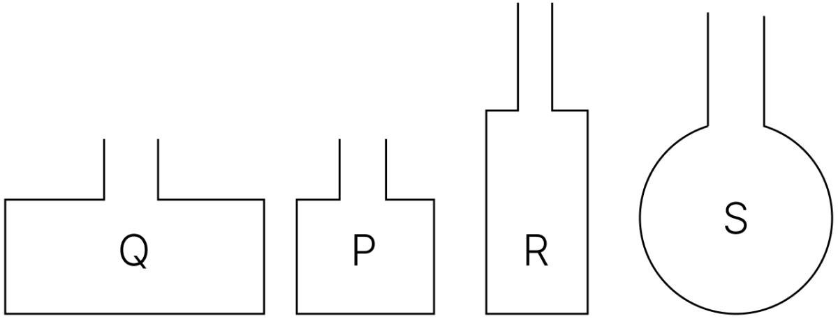
- torque on loop P is maximum.
- torque on loop Q is maximum.
- torque on loop R is maximum.
- torque on loop S is maximum.
Answer
torque on loop S is maximum.
Reason — When a current-carrying loop is placed in a uniform magnetic field, the torque acting on it depends upon :
- Strength of the magnetic field
- Area of the loop
- Magnitude of current flowing
- Orientation of the loop relative to the magnetic field
Here, all four loops are placed with same orientation with same current and magnetic field so now the torque is directly proportional to the area (A) enclosed by the loop.
All four loops are made from wires of the same length (2 m), but different shapes enclose different areas. For a given perimeter, a circular loop encloses the maximum area.
Since loop S is circular, it has the largest area among P, Q, R, and S, and therefore experiences the maximum torque.
How will the direction of force be changed, if the current is reversed in the conductor placed in a magnetic field?
Answer
When the current is reversed in the conductor placed in a magnetic field, the direction of force is also reversed.
What energy conversion does take place during the working of a d.c motor?
Answer
During the working of a d.c. motor electrical energy converts into mechanical energy.
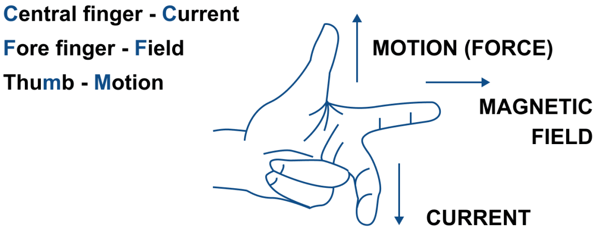
A current flows through a wire in a south to north direction and the magnetic field is directed downwards. In what direction will the force act on the wire?
Answer
The force will act towards West.
Reason — From Fleming's left hand rule, as central finger points towards north (current direction) and forefinger points downwards (magnetic field direction) then thumb will point towards west (force direction).
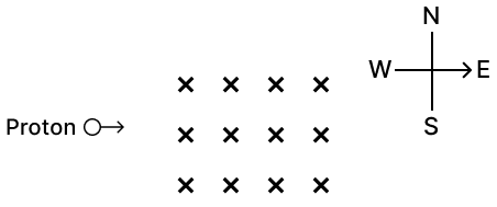
A proton moving towards east enters in a uniform magnetic field directed downwards. Find the direction of the force acting on it.
Answer
The force will act towards North.
Reason — Here direction of current will be same as direction of motion of proton. From Fleming's left hand rule when the central finger points towards east (direction of proton) and forefinger points (downward) then direction of magnetic force will be given by thumb which is pointing in the north direction.
Name three factors on which the magnitude of force on a current carrying conductor placed in a magnetic field depends and state how does the force depend on the factors stated by you.
Answer
Experimentally, it is found that the magnitude of force acting on a current carrying conductor placed in a magnetic field in the direction perpendicular to it's length, depends on the following three factors —
- The force F is directly proportional to the strength of magnetic field B, i.e., F α B
- The force F is directly proportional to the current I flowing in the wire, i.e., F α I
- The force F is directly proportional to the length L of the wire (within the magnetic field) i.e., F α L
State condition in each case for the magnitude of force on a current carrying conductor placed in a magnetic field to be (a) zero, and (b) maximum
Answer
(a) The magnitude of force on a current carrying conductor placed in a magnetic field is zero, when current in conductor is in the direction of magnetic field.
(b) The magnitude of force on a current carrying conductor placed in a magnetic field is maximum, when current in conductor is normal to the magnetic field.
Name and state the law which is used to determine the direction of force on a current carrying conductor placed in a magnetic field.
Answer
The direction of force on a current carrying conductor placed in a magnetic field is obtained by the Fleming's left hand rule.
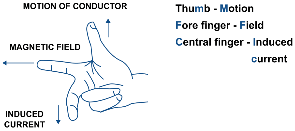
Fleming's left hand rule — Stretch the forefinger, central finger and the thumb of your left hand mutually perpendicular to each other as shown in figure. If the forefinger indicates the direction of magnetic field and the central finger indicates the direction of current, then the thumb will indicate the direction of motion of conductor.
State Fleming's left handle rule.
Answer
Fleming's left hand rule — Stretch the forefinger, central finger and the thumb of your left hand mutually perpendicular to each other as shown in figure. If the forefinger indicates the direction of magnetic field and the central finger indicates the direction of current, then the thumb will indicate the direction of motion of conductor.
What is an electric motor? State its principle.
Answer
An electric motor is a device which converts the electrical energy into the mechanical energy.
Principle — An electric motor (dc motor) works on the principle that on passing electric current through a conductor placed normally in a magnetic field, a force acts on the conductor as a result of which the conductor begins to move and thus mechanical energy (or work) is obtained.
State two ways by which the speed of rotation of an electric motor can be increased.
Answer
The speed of rotation of an electric motor can be increased —
- By increasing the strength of current in the coil.
- By increasing the number of turns in the coil.
Name two appliances in which an electric motor is used.
Answer
Electric motors are used in electrical gadgets like fan, washing machine, etc.
A copper wire is held between the poles of a magnet. There is a switch provided to reverse the current in the wire. Also, the polarity can be changed. In how many directions can the force act on the wire?
Answer
According to Fleming’s Left Hand Rule, the direction of force on a current-carrying conductor placed in a magnetic field depends on:
- Forefinger → Direction of magnetic field (from North to South)
- Middle finger → Direction of current
- Thumb → Direction of the force (motion) on the wire
In this case:
- The current in the wire can flow in 2 directions (forward or reversed using the switch).
- The magnetic field can also be in 2 directions (from North to South or South to North, depending on polarity).
So, the force on the wire can act in:
2 (current directions) x 2 (field directions) = 4 different directions
Thus, the force on the wire can act in 4 possible directions.
The given figure shows the path of three particles A, B and C in a uniform magnetic field (perpendicular to the plane of paper outwards). Identify the nature of charges on them. Name the rule you have used
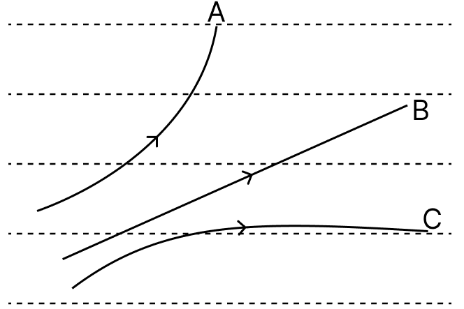
Answer
- Particle A is negatively charged.
- Particle B is uncharged (neutral).
- Particle C is positively charged.
Rule used: Fleming's left-hand rule
Explanation:
According to Fleming's left-hand rule:
- Forefinger shows the direction of magnetic field,
- Middle finger shows the direction of current,
- Thumb shows the direction of force.
Here, the magnetic field is out of the plane of the paper and the particles move towards the right.
For a positive charge, the current is taken in the direction of motion. So, on applying Fleming's left-hand rule, the force acts downwards.
Therefore:
- C, which deflects downwards, is positively charged.
- A, which deflects upwards, is negatively charged, since a negative charge is deflected opposite to a positive charge.
- B remains undeflected, so it is uncharged.
A flat coil ABCD is freely suspended between the poles of a U-shaped permanent magnet with the plane of coil parallel to the magnetic field.
(a) What happens when a current is passed in the coil?
(b) When will the coil come to rest?
(c) When will the couple acting on the coil be (i) maximum, (ii) minimum?
(d) Name an instrument which makes use of the principle stated above.
Answer
(a) When a current is passed in the coil, the coil experiences a torque due to which it rotates.
(b) The coil will come to rest when it's plane becomes normal to the magnetic field.
(c) Maximum — The couple acting on the coil be maximum, when the plane of coil is parallel to the magnetic field.
Minimum — The couple acting on the coil be minimum, when the plane of coil is normal to the magnetic field.
(d) The instrument which makes use of the principle is D.C. Motor.
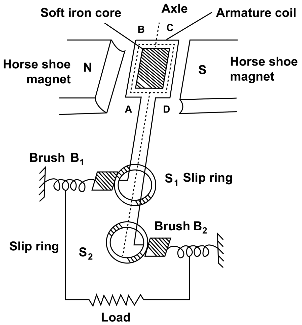
A coil ABCD mounted on an axle is placed between the poles N and S of a permanent magnet as shown in below figure.
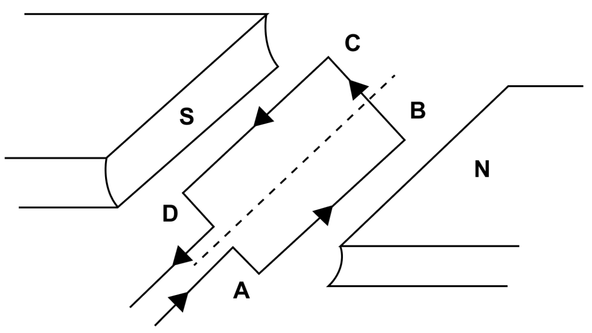
(a) In which direction will the coil begin to rotate when current is passed through the coil in direction ABCD by connecting a battery between the ends A and D of the coil?
(b) Why is a commutator necessary for the continuous rotation of coil?
(c) Complete the diagram with commutator, etc. for the flow of current in the coil.
Answer
(a) The coil begins to rotate in anticlockwise direction, when current is passed through the coil in direction ABCD by connecting a battery between the ends A and D of the coil.
(b) A commutator is necessary for the continuous rotation of coil because the arms AB and CD get interchanged after half rotation, so the direction of torque on coil reverses. To keep the coil rotating in the same direction, a commutator is needed to reverse the direction of current in the coil after each half rotation of coil.
(c) Completed diagram with commutator showing the flow of current in the coil is given below:
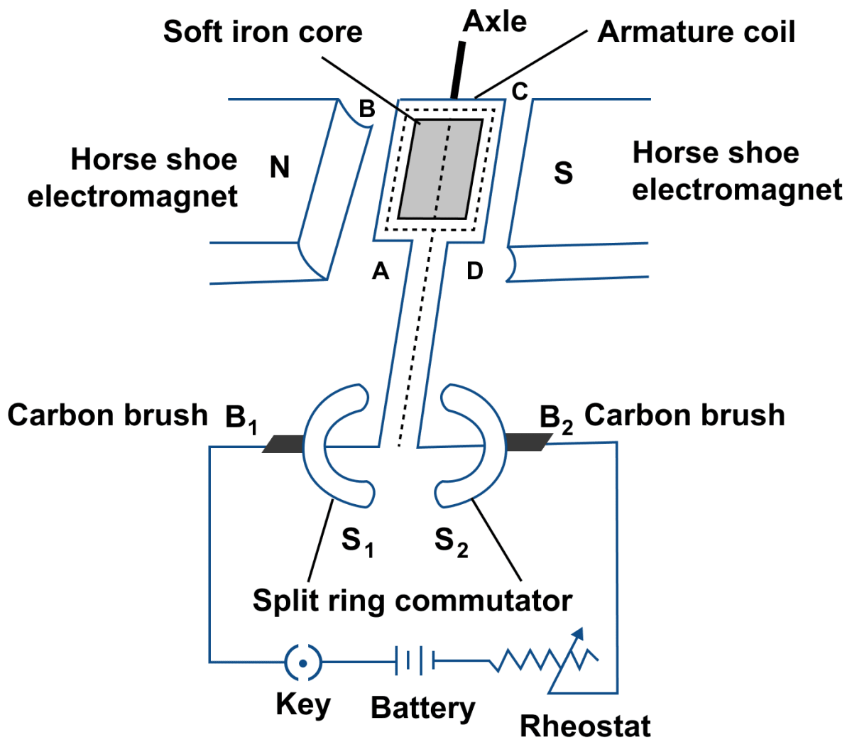
Draw a labelled diagram of a d.c motor showing its main parts.
Answer
Below diagram shows a d.c motor with its parts labelled:
In electromagnetic induction, energy transformation is from :
- Electrical to mechanical
- Mechanical to electrical
- Electrical to chemical
- None of the above
Answer
Mechanical to electrical
Reason — In electromagnetic induction, energy transformation occurs due to the relative motion between a magnetic field and a conductor, which induces an electromotive force (EMF) in the conductor. This induced EMF can then drive an electric current through the conductor, thereby converting mechanical energy into electrical energy.
The magnitude of induced emf depends on the :
- number of turns in the coil
- rate of change of magnetic flux linked with each turn
- current
- Both the number of turns in the coil and the rate of change of magnetic flux through it
Answer
Both the number of turns in the coil and the rate of change of magnetic flux through it
Reason — The magnitude of induced emf depends on the :
- number of turns in the coil
- rate of change of magnetic flux linked with each turn
Lenz's law is based on :
- conservation of momentum
- conservation of energy
- conservation of force
- none of the above
Answer
conservation of energy
Reason — Lenz's law is based on the law of conservation of energy. It shows that the mechanical energy is spent in doing work against the opposing force experienced by the moving magnet, and it is transformed into the electrical energy due to which current flows in the solenoid.
In an a.c. generator the coil makes n rotations per second. The magnitude of induced emf at any instant t is given by :
- e = io sin 2πnt
- e = eo sin 2πnt
- e = eo sin 2πn/t
- e = eo cos 2πnt
Answer
e = eo sin 2πnt
Reason — In an a.c. generator the coil makes n rotations per second. The magnitude of induced emf at any instant is given by e = eo sin 2πnt.
A current of constant magnitude and unique direction is called ............... while a current changing its magnitude and direction periodically is called ............... .
- a.c., d.c.
- d.c., a.c.
- a.c., a.c.
- d.c., d.c.
Answer
d.c., a.c.
Reason — A current of constant magnitude and unique direction is called direct current (d.c.).
A current changing its magnitude and direction periodically is called alternating current (a.c.).
The direction of induced current is obtained by:
- Fleming's left hand rule
- Clock rule
- Right hand thumb rule
- Fleming's right hand rule
Answer
Fleming's right hand rule
Reason — The direction of induced current is obtained by Fleming's right hand rule.
Fleming's right hand rule — Stretch the thumb, central finger and forefinger of your right hand mutually perpendicular to each other. If the forefinger indicates the direction of magnetic field and the thumb indicates the direction of motion of the conductor, then the central finger will indicate the direction of induced current.
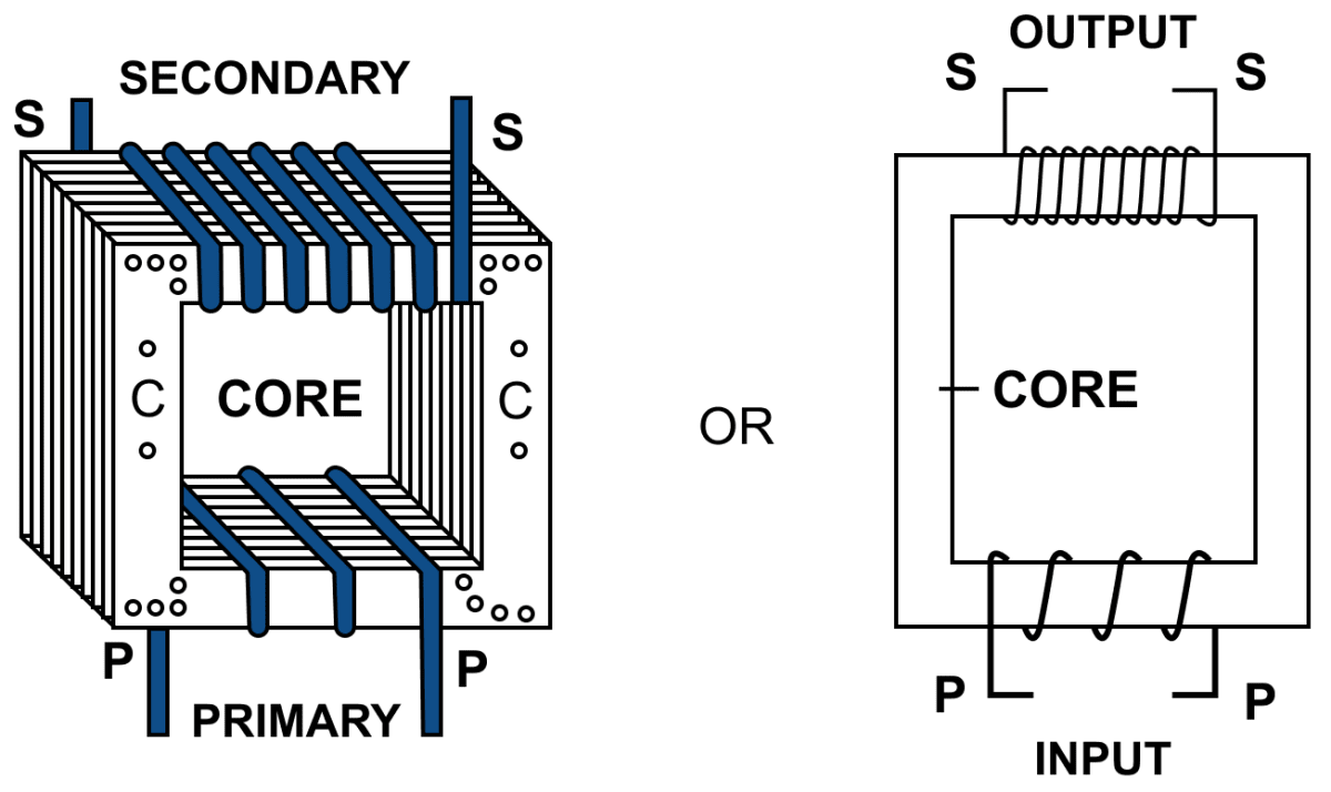
In a step up transformer:
- Ns = Np
- Ns < Np
- Ns > Np
- nothing can be said
Answer
Ns > Np
Reason — In a step up transformer the number of turns in the secondary coil is more than the number of turns in the primary coil (Ns > Np) i.e., turns ratio n > 1. which increases the a.c. voltage and decreases the current. i.e., Es > Ep and Is < Ip.
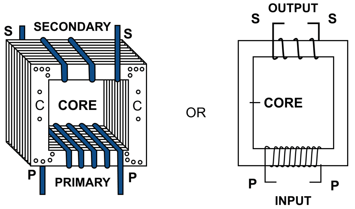
A step up transformer ............... the current whereas a step down transformer ............... the current.
- increases, increases
- decreases, decreases
- decreases, increases
- increases, decreases
Answer
decreases, increases
Reason — In a step up transformer the number of turns in the secondary coil is more than the number of turns in the primary coil ( Ns > Np) i.e., turns ratio n > 1 which increases the a.c. voltage and decreases the current. i.e., Es > Ep and Is < Ip.
In a step down transformer the number of turns in the secondary coil is less than the number of turns in the primary coil (Ns < Np) i.e., turns ratio n < 1 which decreases the a.c. voltage and increases the current. i.e., Es < Ep and Is > Ip.
Out of the following, which statement is incorrect ?
- The lamination of core prevents loss of energy due to eddy currents.
- The core is made of soft iron.
- A transformer can be used with d.c.
- A closed core is used so as to provide a closed path for magnetic field lines.
Answer
A transformer can be used with d.c.
Reason — Transformers are used with a.c. circuits to step up or step down voltage. In d.c. circuits, since the current is constant, induction cannot happen. Therefore, transformers are not used with d.c. circuits.
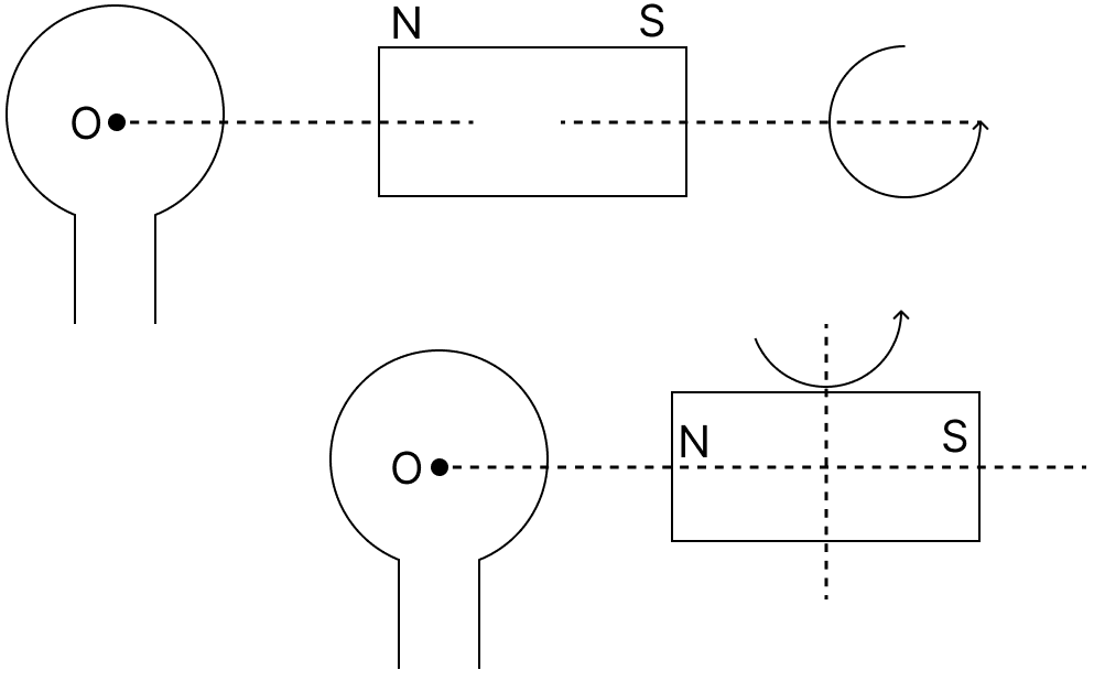
A bar magnet is kept along the axis of a circular coil as shown in the figure given below. The magnet is rotated (i) about its own axis and (ii) about an axis perpendicular to the length of the magnet. The induced emf is generated at the terminals of the coil in :
- (i) only
- (ii) only
- none of the cases
- both the cases
Answer
(ii) only
Reason — Induced emf is produced only when there is a change in magnetic flux through the coil.
When the magnet is rotated about its own axis (i), the magnetic field linked with the coil does not change, so no emf is induced.
However, when it is rotated about an axis perpendicular to its length (ii), the magnetic flux through the coil changes continuously, thus inducing an emf.
Hence, the induced emf is generated at the terminals of the coil in (ii) only
(i) The number of turns in the secondary coil of a transformer is 20 times than that in a primary coil. If the power fed to the primary coil is 100 W (assume no energy loss), then what is the power output at the secondary coil ?
- 5 W
- 100 W
- 2000 W
- 4000 W
(ii) If the primary coil of the above transformer is supplied with 10 V, what is the voltage of the secondary coil ?
- 0.5 V
- 10 V
- 200 V
- 100 V
Answer
(i) 100 W
(ii) 200 V
Reason —
(i) In an ideal transformer (no energy loss), the input power equals output power. Therefore, even though the number of turns changes, the power remains the same.
Hence, the secondary coil also delivers 100 W.
(ii) Given,
- Ratio of number of turns in the secondary coil to the primary coil = 20
- Voltage of the primary coil = 10 V
In a transformer, voltage is proportional to the number of turns i.e.,
Hence, the voltage of the secondary coil is 200 V.
An electron moves on a straight line path XY as shown. abcd is a coil adjacent to the path of electron. The direction of induced current, if any, in the coil will be :
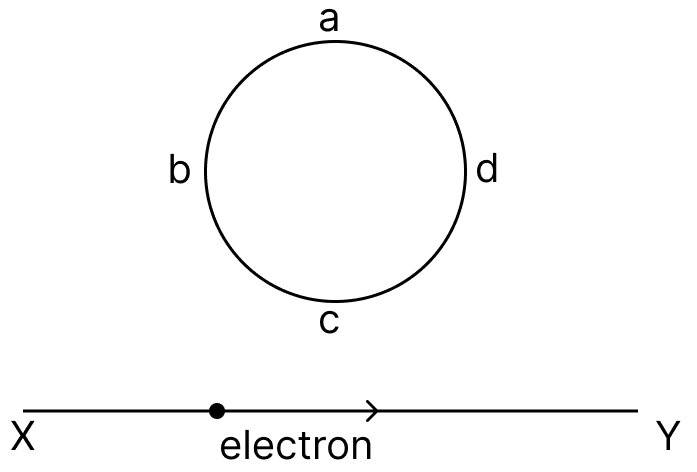
- No curent is induced
- abcd
- adcb
- No fixed direction
Answer
adcb
Reason — As the electron moves away, the magnetic flux through the coil decreases. By Lenz’s law, the induced current flows so as to oppose this decrease. That requires the coil to produce magnetic field into the plane of the paper, which is produced by a clockwise current. In the given diagram, clockwise is adcb.
Hence, the direction of induced current in the coil will be adcb.
The north pole of a magnet is brought near a metallic ring as shown in the figure given below. The direction of induced current will be :
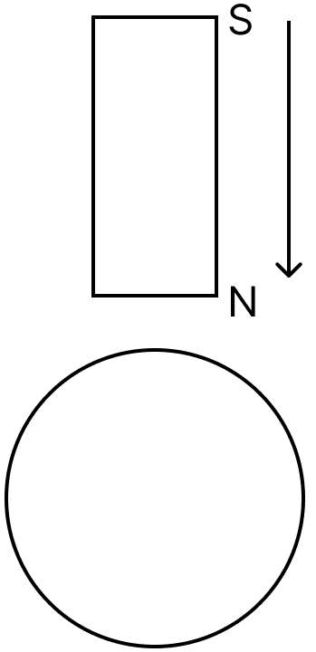
- anticlockwise
- clockwise
- first anticlockwise and then clockwise
- first clockwise and then anticlockwise
Answer
anticlockwise
Reason — As the north pole of the magnet is brought closer to the metallic ring, the magnetic flux through the ring increases.
According to Lenz’s law, the induced current flows in such a direction as to oppose this increase in flux so to oppose the approaching north pole, the face of the ring towards the magnet must behave like a north pole.
For a circular loop, this happens when the current flows anticlockwise (as seen from the magnet side).
Hence, the direction of induced current will be anticlockwise.
Two thin wires carrying same currents lie on X and Y axis as shown in the figure. The origin of axis is O. The magnetic field will be zero on line :
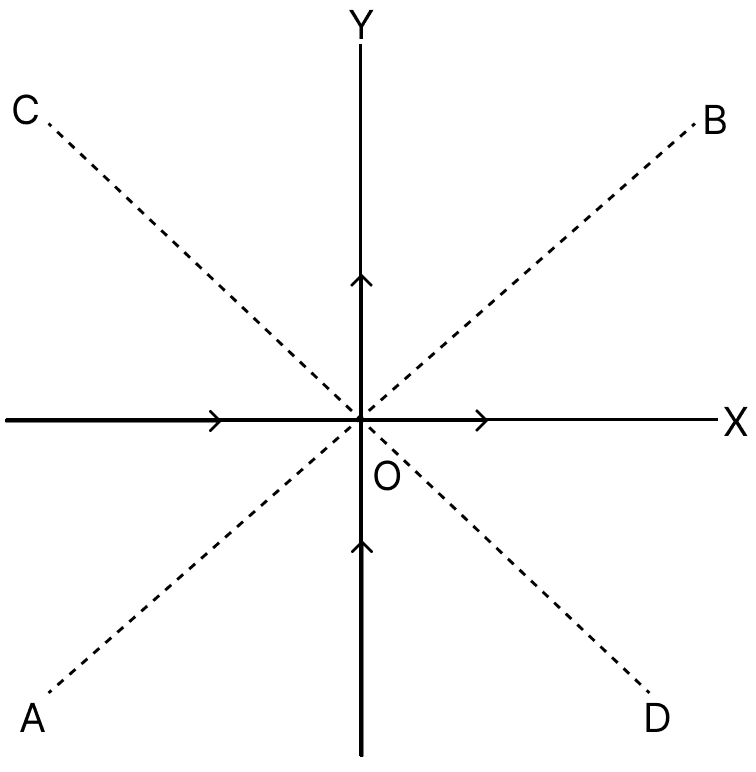
- AB
- CB
- part OB of line AB
- part OC of line CD
Answer
AB
Reason — The magnetic field around a straight current-carrying conductor is given by the right-hand thumb rule.
- For the wire along OX, at points above the X-axis, the magnetic field is out of the plane of the paper.
- For the wire along OY, at points to the right of the Y-axis, the magnetic field is into the plane of the paper.
Thus, on line AB, the magnetic fields due to the two wires are in opposite directions.
Also, every point on line AB is equidistant from the X-axis and Y-axis, so the magnitudes of the two magnetic fields are equal, since both wires carry the same current.
Therefore, the two magnetic fields cancel each other on AB.
Hence, the magnetic field is zero on line AB.
Assertion (A): A current carrying solenoid when suspended freely sets itself in the north-south direction just like a bar magnet.
Reason (R): The end of the solenoid where the direction of current is anti-clockwise behaves as a north pole and the end where the direction of the current is clockwise behaves as a south pole.
- both A and R are true and R is the correct explanation of A
- both A and R are true and R is not the correct explanation of A
- assertion is false but reason is true
- assertion is true but reason is false.
Answer
both A and R are true and R is not the correct explanation of A.
Explanation
Assertion (A) is true. A current-carrying solenoid behaves like a magnet and aligns itself in the north-south direction when freely suspended, similar to a bar magnet. This behavior is due to the magnetic field produced by the current flowing through the solenoid.
Reason (R) is true. The direction of the magnetic field inside a solenoid depends on the direction of the current. The end of the solenoid where the current circulates anti-clockwise acts as a north pole, while the end where the current circulates clockwise acts as a south pole.
But here reason does not justify its assertion.
Assertion (A): The strength of the magnetic field produced due to a current carrying circular coil increases with an increase in the strength of the current.
Reason (R): Magnetic field strength is inversely proportional to the current flowing in a coil.
- both A and R are true and R is the correct explanation of A
- both A and R are true and R is not the correct explanation of A
- assertion is false but reason is true
- assertion is true but reason is false.
Answer
assertion is true but reason is false.
Explanation
Assertion (A) is true. The strength of the magnetic field produced due to a current carrying circular coil increases with an increase in the strength of the current. This is consistent with Ampere's law, which states that the magnetic field is directly proportional to the current flowing through the coil.
Reason (R) is false. The magnetic field strength is directly proportional to the current flowing through a coil, not inversely proportional.
Assertion (A): A transformer can increase the voltage of an alternating e.m.f.
Reason (R): This is achieved by keeping the number of turns in the secondary coil less than the number of turns in the primary coil.
- both A and R are true and R is the correct explanation of A
- both A and R are true and R is not the correct explanation of A
- assertion is false but reason is true
- assertion is true but reason is false.
Answer
assertion is true but reason is false.
Explanation
Assertion (A) is true. A transformer can increase the voltage of an alternating electromotive force (e.m.f.). This is accomplished through electromagnetic induction, where a changing magnetic field in the primary coil induces a voltage in the secondary coil.
Reason (R) is false. To increase the voltage in the secondary coil, the number of turns in the secondary coil must be greater than the number of turns in the primary coil, not less. This allows for a step-up transformation of voltage.
Assertion (A): A transformer cannot be used with a direct current.
Reason (R): The lamination of core prevents the loss of energy due to induced currents in the core.
- both A and R are true and R is the correct explanation of A
- both A and R are true and R is not the correct explanation of A
- assertion is false but reason is true
- assertion is true but reason is false.
Answer
both A and R are true R is not the correct explanation of A.
Explanation
Assertion (A) is true. A transformer cannot be used with direct current (DC) because it relies on the principle of electromagnetic induction, which requires a changing magnetic field. In DC, the current flows in one direction without changing, so there is no alternating magnetic field to induce voltage in the secondary coil of the transformer.
Reason (R) is true. The lamination of the core in a transformer is used to prevent energy loss due to induced currents in the core, known as eddy currents. By laminating the core, the magnetic flux is confined to the individual lamination, reducing the eddy current losses
Assertion (A): The magnitude of induced e.m.f. becomes maximum when the magnetic flux linked with the coil reduces to zero from its maximum value.
Reason (R): This happens when the plane of the coil lies in the direction of the magnetic field.
- both A and R are true and R is the correct explanation of A
- both A and R are true and R is not the correct explanation of A
- assertion is false but reason is true
- assertion is true but reason is false.
Answer
both A and R are true and R is the correct explanation of A.
Explanation
Assertion (A) is true. According to Faraday's law of electromagnetic induction, the magnitude of the induced electromotive force (e.m.f.) in a coil is maximum when the rate of change of magnetic flux through the coil is maximum. This occurs when the magnetic flux linked with the coil reduces to zero from its maximum value, resulting in the maximum rate of change of magnetic flux.
Reason (R) is true. This happens when the plane of the coil lies in the direction of the magnetic field. When the coil is in this position, the magnetic flux through the coil is changing most rapidly, resulting in the maximum induced e.m.f.
(a) What kind of the energy change takes place when a magnet is moved towards a coil having a galvanometer between its ends?
(b) Name the phenomenon.
Answer
(a) When a magnet is moved towards a coil having a galvanometer between it's ends then mechanical energy changes to the electrical energy.
(b) The phenomenon is known as Electromagnetic Induction.
Complete the following sentence —
The current is induced in a closed circuit only if there is ............... .
Answer
The current is induced in a closed circuit only if there is change in number of magnetic field lines linked with the circuit.
In which of the following cases e.m.f. is induced?
(i) A current is started in a wire held near a loop of wire.
(ii) The current is switched off in a wire held near a loop of wire.
(iii) A magnet is moved through a loop of wire.
(iv) A loop of wire is held near a magnet.
Answer
(i) Yes, e.m.f. is induced because when current is started in a wire held near a loop of wire, magnetic field varies due to which e.m.f. is induced.
(ii) Yes, e.m.f. is induced because when current is switched off in a wire held near a loop of wire, the current stops and magnetic field again varies and hence e.m.f. is induced.
(iii) Yes, e.m.f. is induced. When there is a relative motion between the magnet and a loop of wire, magnetic flux changes and e.m.f. is induced.
(iv) No, e.m.f. is not induced. When a loop of wire is held near a magnet, there is no change in magnetic field hence e.m.f. is not induced.
What determines the frequency of a.c. produced in a generator?
Answer
The frequency of rotations of the coil (i.e., the number of rotations of the coil per second) determines the frequency of a.c. produced in a generator.
Complete the sentence —
An a.c. generator changes the ............... energy to ............... energy.
Answer
An a.c. generator changes the mechanical energy to electrical energy.
What energy conversion does take place in a generator when it is in use?
Answer
The mechanical energy changes into the electrical energy in a generator when it is in use.
State one advantage of using an a.c. over the d.c.
Answer
The advantage of a.c. over d.c. is that it is cheaper and easy to generate a.c. than d.c.
How are the e.m.f. in the primary and secondary coils of a transformer related with the number of turns in these coils?
Answer
E.m.f. in the primary and secondary coils of a transformer are related with the number of turns in these coils as follows —
=
where s stands for secondary, p stands for primary, E is E.m.f and N is number of turns in the coils .
Complete the following sentences —
(i) In a step up transformer, the number of turns in the primary are ............... than the number of turns in the secondary.
(ii) The transformer is used in ............... current circuits.
(iii) In a transformer, the frequency of a.c. voltage ............... (increase / decreases / remains same).
Answer
(i) In a step up transformer, the number of turns in the primary are less than the number of turns in the secondary.
(ii) The transformer is used in alternating current circuits.
(iii) In a transformer, the frequency of a.c. voltage remains same.
Name the material of the core in (a) an electric bell, (b) electromagnet, (c) a d.c. motor, (d) an a.c. generator, and (e) a transformer.
Answer
The material used in —
(a) an electric bell — soft iron core
(b) electromagnet — soft iron core
(c) a d.c. motor — soft iron core
(d) an a.c. generator — soft iron core
(e) a transformer — soft iron core
State Faraday's laws of electromagnetic induction.
Answer
Faraday formulated the following two laws of electromagnetic induction —
- Whenever there is a change in magnetic flux linked with a coil, an e.m.f. is induced. The e.m.f. induced lasts so long there is a change in the magnetic flux linked with the coil.
- The magnitude of e.m.f. induced is directly proportional to the rate of change of magnetic flux linked with the coil. If magnetic flux changes at a constant rate, a steady e.m.f. is produced.
State two factor on which the magnitude of induced e.m.f in a coil depend.
Answer
The magnitude of induced e.m.f. in a coil depend on following two factors —
- The rate of change in magnetic flux with each turn of coil, and
- The number of turns in the coil.
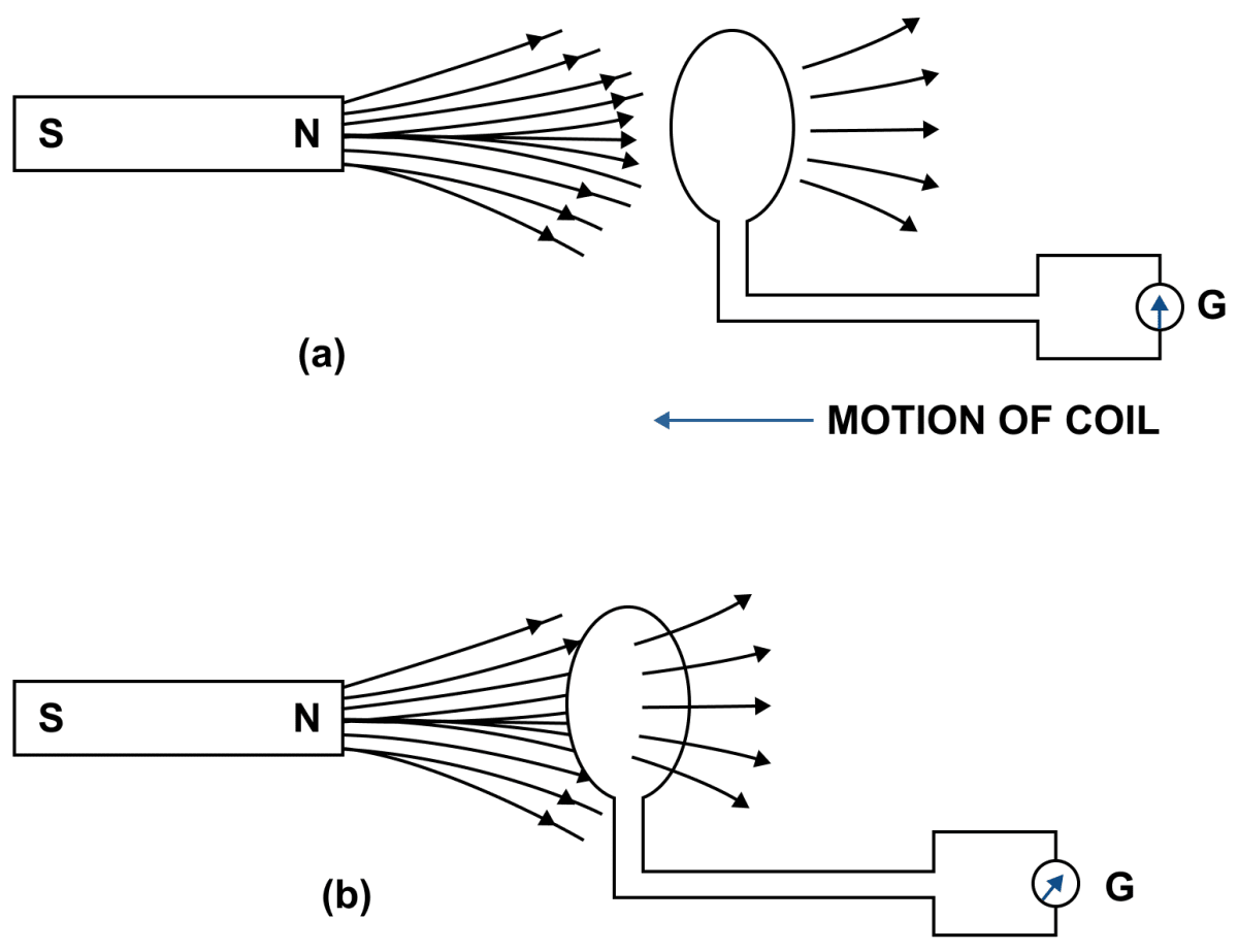
(a) How would you demonstrate that a momentary current can be obtained by the suitable use of a magnet, a coil of wire and a galvanometer?
(b) What is the source of energy associated with the current obtained in part (a)?
Answer
(a) When there is a relative motion between the coil and magnet, magnetic flux linked with the coil changes. As shown in figure b, the coil is moved towards the north pole of magnet, so the magnetic flux through the coil increases. Similarly, if the coil is moved away from the north pole of magnet, the magnetic flux through the coil decreases.
Due to change in the magnetic flux linked with the coil, an e.m.f. is induced in the coil. The induced e.m.f. causes a current to flow in the coil if the circuit of coil is closed.
(b) the source of energy associated with the current obtained in part (a) is the Mechanical energy spent in moving the magnet relative to the coil.
State Fleming's right hand rule.
Answer
Fleming's right hand rule — Stretch the thumb, central finger and forefinger of your right hand mutually perpendicular to each other. If the forefinger indicates the direction of magnetic field and the thumb indicates the direction of motion of the conductor, then the central finger will indicate the direction of induced current.
What is Lenz's law?
Answer
According to Lenz's law, the direction of induced e.m.f. (or induced current) is such that it opposes the cause which produces it.
Why does it become more difficult to move a magnet towards a coil when the number of turns in the coil has been increased ?
(Hint : e.m.f. induced in the coil and hance the magnetic field induced by it, becomes more when the number of turns in the coil are increased. The stronger field induced opposes the motion of the magnet towards the coil).
Answer
According to Lenz's law, the direction of induced e.m.f. (or induced current) is such that it opposes the cause which produces it. As per Faraday's laws of Electromagnetic Induction, the magnitude of induced e.m.f. is directly proportional to the number of turns in the coil.
Hence, the e.m.f. induced in the coil becomes more when the number of turns in the coil are increased. As a result, a stronger magnetic field is induced that opposes the motion of magnet towards the coil with a greater force making it more difficult to move the magnet towards the coil.
Explain why an induced current must flow in such a direction so as to oppose the change producing it.
Answer
Due to law of conservation of energy, the mechanical energy spent in producing the change is transformed into the electrical energy in form of the induced current. Hence, the induced current flows in a direction to oppose the change so that some mechanical energy is constantly required to overcome the opposing force which in turn will keep the induced current flowing.
Name and state the principle of a simple a.c. generator. What is its use?
Answer
An A.C. generator is a device which converts the mechanical energy into the electrical energy using the principle of electromagnetic induction.
Principle — In a generator, a coil is rotated in a magnetic field. Due to rotation, the magnetic flux linked with the coil changes and therefore an e.m.f. is induced between the ends of the coil. Thus, a generator acts as a source of current in an external circuit containing load when connected between the ends of it's coil.
Use — We use a.c. generator in our house as an alternative source of electricity when electric supply from mains is not available.
In an a.c generator, the speed at which the coil rotates is doubled. How would this affect (a) the frequency of output voltage (b) the maximum output voltage.
Answer
(a) When in an a.c generator the speed at which the coil rotates is doubled the frequency of output voltage is also doubled.
(b) The maximum output voltage is also doubled when the speed at which the coil rotates is doubled.
State two ways to produce a higher e.m.f. in an a.c generator.
Answer
Two ways to produce a higher e.m.f. in an a.c. generator are —
- By increasing the speed of rotation of coil.
- By increasing the number of turns in the coil.
State (i) two dis-similarities, and (ii) two similarities between a d.c. motor and an a.c. generator.
Answer
(i) Dis-similarities between a d.c. motor and an a.c. generator are —
| D.C. motor | A.C. generator |
|---|---|
| A d.c. motor is a device which converts the electrical energy into the mechanical energy. | A generator is a device which converts the mechanical energy into the electrical energy. |
| A d.c. motor works on the principle of force acting on a current carrying conductor placed in a magnetic field. | A generator works on the principle of electromagnetic induction. |
(ii) Similarities between a d.c. motor and an a.c. generator are —
(i) Both in d.c. motor and an a.c. generator, a coil rotates in a magnetic field between the pole pieces of a powerful electromagnet.
(ii) Both in a d.c. motor and an a.c. generator, there is a transformation of energy from one form to the other form.
For what purpose are the transformers used? On which type of current do transformers work?
Answer
Transformers are used to step up or step down the a.c. voltage. They work on a.c. current.
State two factors on which the magnitude of an induced e.m.f. in the secondary coil of a transformer depends.
Answer
Factors on which the magnitude of an induced e.m.f. in the secondary coil of a transformer depends are —
- The turns ratio i.e., the number of turns in the secondary coil to the number of turns in the primary coil.
- The input voltage.
Name the device used to transform 12 V a.c. to 200 V a.c. Name the principle on which it works.
Answer
The device used to transform 12 V a.c. to 200 V a.c. is step up transformer. It works on the principle of electromagnetic induction.
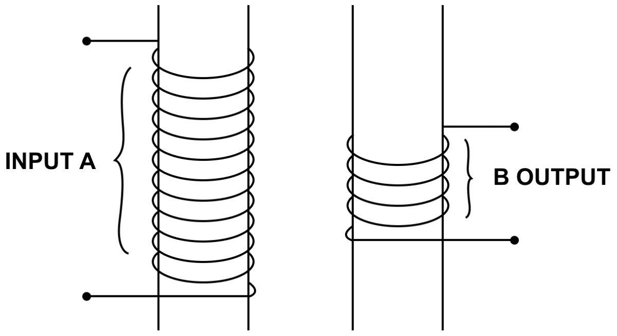
Name the coil of which the wire is thicker in a (i) step up, (ii) step down transformer. Give reason to your answer.
Answer
(i) Step up transformer — The wire in the primary coil is thicker than that in the secondary coil. It is done because the current in the primary coil is more than in the secondary coil and a thick wire results in less resistance and therefore less loss of energy as heat.
(ii) Step down transformer — The wire in the secondary coil is thicker than that in the primary coil. It is done so because the current in the secondary coil is more than in the primary coil and a thick wire results in less resistance and therefore less loss of energy as heat.
The output current of a transformer in which the voltage is stepped down is usually higher than the input current. Explain why.
Answer
For an ideal transformer, input power is equal to the output power. From relation P = VI, (where P is power, V is voltage and I is current) , we know that V and I are inversely related. In a step down transformer voltage is decreased and in order to keep the power same the output current increases.
Why is the iron core of a transformer made laminated (thin sheets) instead of being in one solid piece.
Answer
The laminated core prevents the loss of energy due to induced (or eddy) currents in the core. Hence, it is made laminated (thin sheets) instead of being in one solid piece.
Name two kinds of energy losses in a transformer. How are they minimized?
Answer
The two kinds of energy losses are —
- Loss of energy due to induced (or eddy) currents. The use of laminated core prevents this loss of energy.
- Hysteresis loss — The use of soft iron for the core helps in minimization of this loss.
Give two points of difference between a step up and step down transformer.
Answer
Difference between a step up transformer and step down transformer are:
| Step up transformer | Step down transformer |
|---|---|
| It increases the a.c. voltage and decreases the current. i.e., Es > Ep and Is < Ip. | It decreases the a.c. voltage and increases the current i.e., Es < Ep and Is > Ip. |
| The wire in the primary coil is thicker than that of the secondary coil. | The wire of the secondary coil is thicker than the primary coil. |
Name the transformer used in the (i) power generating station, (ii) power sub-station. State the function of each transformer.
Answer
The transformer used in the —
(i) Power generating station — Step up transformer is used in Power generating station to increase the alternating voltage from 11 kV to 132 kV.
(ii) Power sub station — Step down transformer is used in Power sub station to decrease the alternating voltage from 132 kV to 33 kV and then further to 11 kV and to 220 V.
(a) What is electromagnetic induction?
(b) Describe one experiment to demonstrate the phenomenon of electromagnetic induction.
Answer
(a) Whenever there is a change in the number of magnetic field lines linked with a conductor, an electromotive force (e.m.f.) is developed between the ends of the conductor which lasts as long as there is a change in the number of magnetic field lines through the conductor. This phenomenon is called the electromagnetic induction.
(b) Demonstration of the phenomenon of electromagnetic induction —
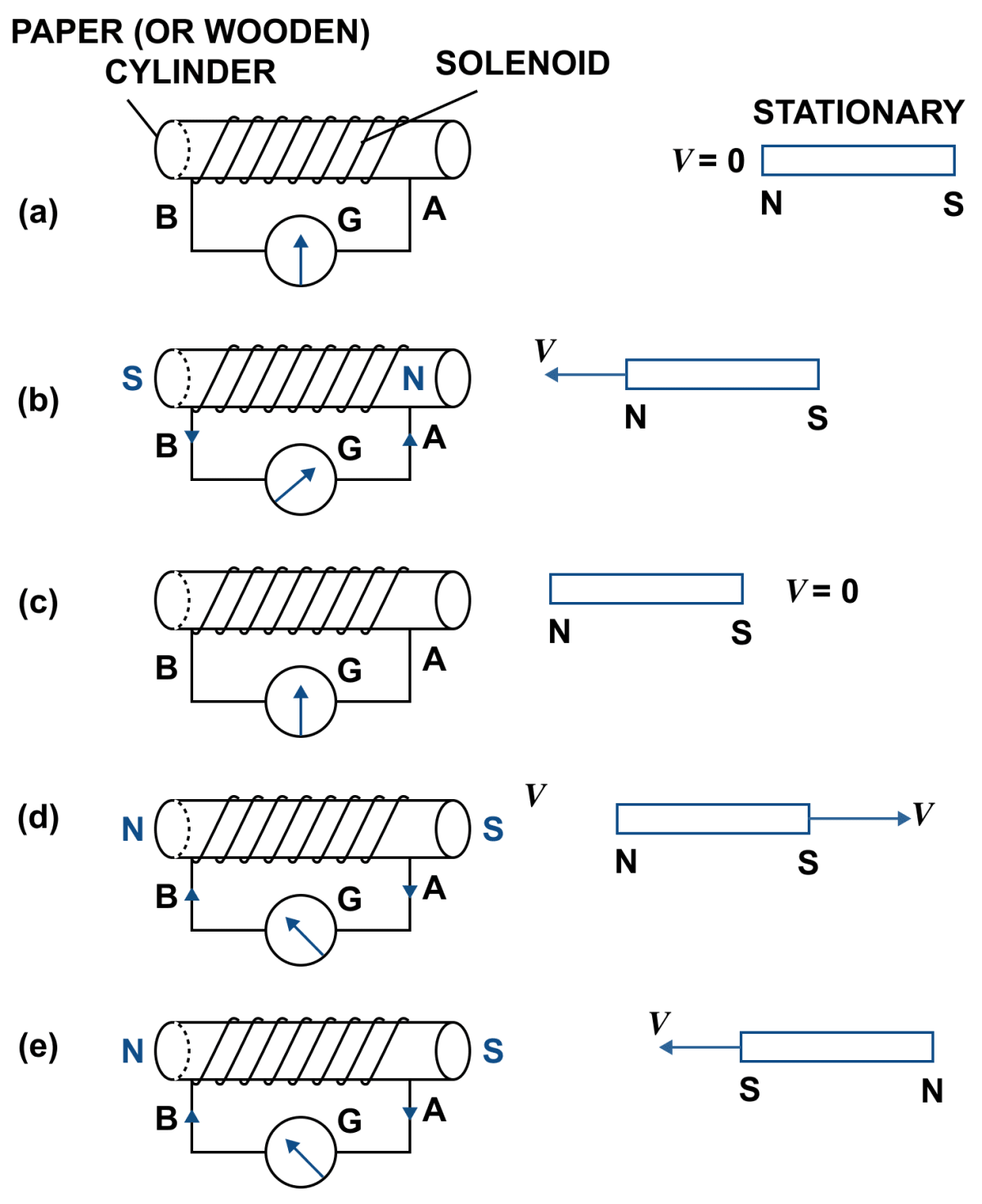
Experiment — Wind an insulated copper wire in form of a spiral on a paper (or wooden) cylinder so as to form a coil in the form of a solenoid. Connect a centre zero galvanometer G between the two ends of the solenoid. Then, place a magnet NS at some distance along the axis of solenoids as shown in figure.
Observations — It is observed that,
(i) When the magnet is stationary, there is no deflection in galvanometer and it's pointer reads zero as shown in figure (a).
(ii) When the magnet with it's north pole facing the solenoid is moved towards it, the galvanometer shows a deflection towards right showing that a current flows in solenoid in the direction B to A as shown in figure (b).
(iii) As the motion of magnet is stopped, the pointer of galvanometer comes to zero position. Fig. (c) This shows that the current in solenoid flows as long as the magnet is in motion.
(iv) If the magnet is moved away from the solenoid, the pointer of galvanometer deflects towards left (as shown in figure d) showing that the current in solenoid flows again, but now in direction A to B which is opposite to that as shown in figure b. Current becomes zero as soon as the magnet stops.
(v) If the same action (movement) of magnet is done rapidly, the deflection in the galvanometer is more than before although the direction of deflection remains same. It shows that now more current flows.
(vi) If the magnet is brought towards the solenoid by keeping it's south pole towards it, the pointer of galvanometer deflects towards left as shown in figure (e) showing that the current in solenoid flows in direction A to B which is opposite to that shown in figure (b)
(a) Describe briefly one way of producing an induced e.m.f.
(b) State one factor that determines the magnitude of induced e.m.f. in part (a) above.
(c) What factor determines the direction of induced e.m.f. in part (a) above?
Answer
(a) When there is a relative motion between the coil and magnet, magnetic flux linked with the coil changes. As shown in figure b, the coil is moved towards the north pole of magnet, so the magnetic flux through the coil increases. Similarly, if the coil is moved away from the north pole of magnet, the magnetic flux through the coil decreases. Due to change in the magnetic flux linked with the coil, an e.m.f. is induced in the coil. The induced e.m.f. causes a current to flow in the coil if the circuit of coil is closed.
(b) The magnitude of induced e.m.f. depends on the rate of change of magnetic flux linked with each turn.
(c) The direction of induced e.m.f. depends on whether there is an increase or decrease in the magnetic flux. It can be determined by any of the following two rules (i) Fleming's right hand rule, (ii) Lenz's law.
Explain how does the Lenz's law show the conservation of energy in the phenomenon of electromagnetic induction.
Answer
Lenz's law is based on the law of conservation of energy. It shows that the mechanical energy is spent in doing work against the opposing force experienced by the moving magnet, and it is transformed into the electrical energy due to which current flows in the solenoid.
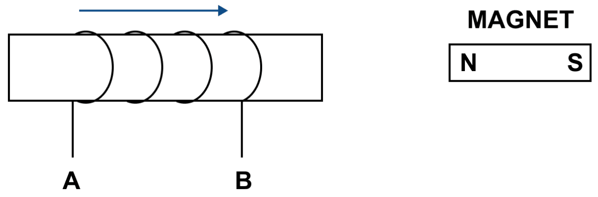
The diagram in below figure shows a coil of several turns of copper wire near a magnet NS. The coil is moved in the direction of arrow shown in the diagram.
(i) In what direction does the induced current flow in the coil?
(ii) Name the law used to arrive at the conclusion in part (i).
(iii) How would the current in coil be altered if:
(a) the coil has twice the number of turns,
(b) the coil was made to move three times fast?
Answer
(i) When north pole of the magnet is brought towards the end B of the solenoid, the induced current flows in the solenoid in direction A to B i.e., at the end B, the current is anticlockwise, so the end B of the solenoid becomes a north pole to repel the magnet. Thus it opposes the motion of north pole of the magnet towards the solenoid, which is the cause producing it.
(ii) The law used to arrive at the conclusion in part (i) is Lenz's law.
(iii) (a) Current is directly proportional to the number of turns. Hence, current becomes twice when the coil has twice the number of turns.
(b) The current in coil becomes thrice when the coil was made to move three times fast .
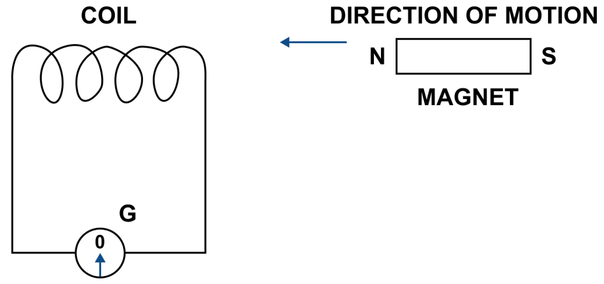
The diagram in below figure shows a fixed coil of several turns connected to a centre zero galvanometer G and a magnet NS which can move in the direction shown in the diagram.
(a) Describe the observation in the galvanometer if (i) the magnet is moved rapidly, (ii) the magnet is kept stationary after it has moved into the coil, (iii) the magnet is then rapidly pulled out of the coil.
(b) How would the observation in (i) of part (a) change if a more powerful magnet is used?
Answer
(a) (i) A deflection is observed in the galvanometer towards the right when the magnet is moved away rapidly.
(ii) The deflection becomes zero, when the magnet is kept stationary after it has moved into the coil.
(iii) The deflection again occurs in opposite direction, when the magnet is rapidly pulled out of the coil.
(b) When a more powerful magnet is used then the deflection is increased.
Draw a labelled diagram of a simple a.c generator.
Answer
Labelled diagram of a simple a.c generator is given below:
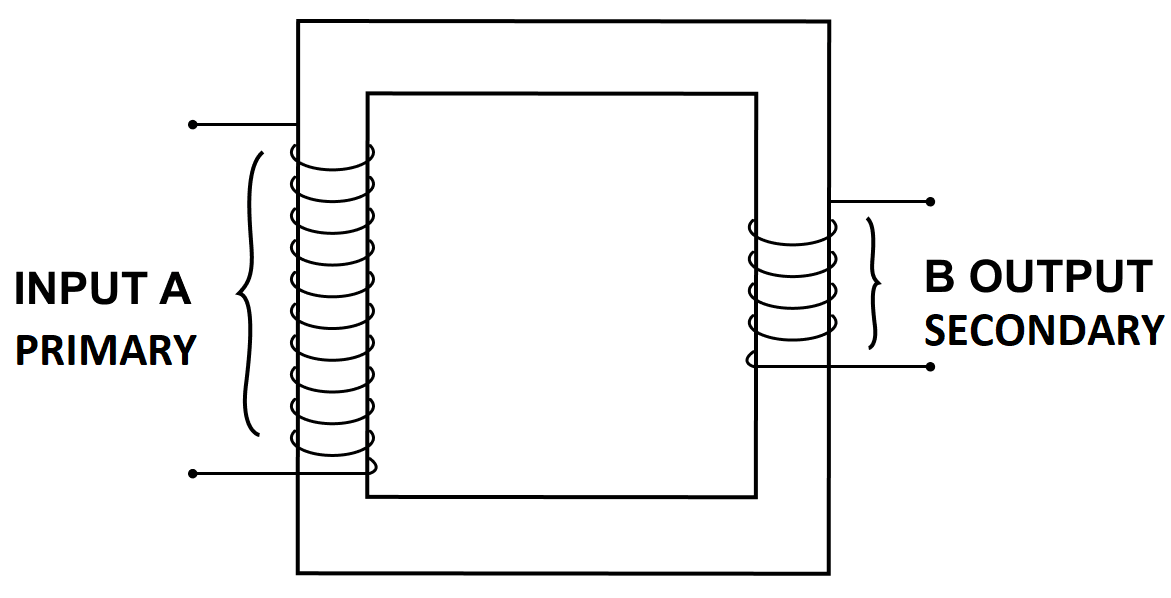
Draw a labelled diagram to show the various components of a step up transformer.
Answer
Below diagrams shows the various components of a step up transformer:
Draw a labelled diagram of a step up transformer and explain how does it work. State two characteristics of the primary coil as compared to it's secondary coil.
Answer
Labelled diagram of a step up transformer is given below:
The transformer used to change a low alternating voltage to a high alternating voltage (of same frequency) is called a step up transformer (i.e. Es > Ep).
When the terminals of primary coil are connected to the source of alternating e.m.f. a varying current flows through the primary coil. This varying current produces a varying magnetic field in the core of the transformer.Thus the magnetic flux linked with the secondary coil vary due to which an e.m.f. is induced in it. The induced e.m.f. varies in the same manner as the applied e.m.f. in the primary coil varies and thus the induced e.m.f. has the same frequency as that of the applied e.m.f.
In a step up transformer the number of turns in the secondary coil is more than the number of turns in the primary coil ( Ns > Np) i.e., turns ratio n > 1 as shown above.
Since current in primary coil is more than in the secondary coil (or Ip > Is), so the wire in the primary coil is kept thicker than in the secondary coil.
Two characteristics of the primary coil as compared to it's secondary coil are —
- The number of turns in the primary coil are less than that of the secondary coil.
- The wire of the primary coil is thicker than that of the secondary coil.
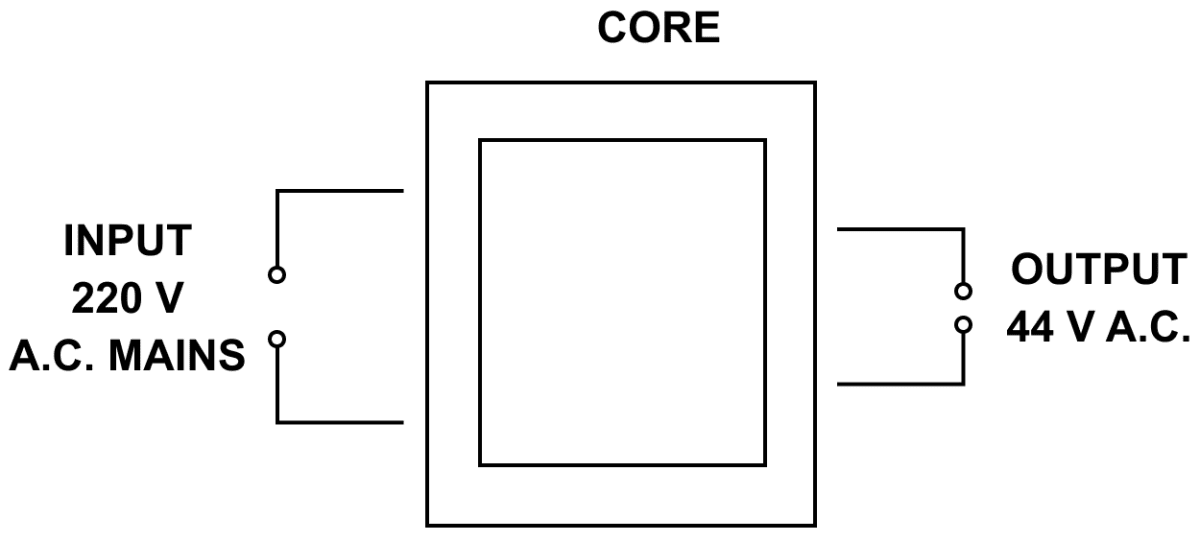
Draw a labelled diagram of a device you would use to transform 220 V a.c. to 15 V a.c. Name the device and explain how does it work. Give its two uses.
Answer
The labelled diagram of a device used to transform 220 V a.c. to 15 V a.c. is given below:
Name of this device is Step Down Transformer. It is used to change a high alternating voltage to a low alternating voltage (of same frequency).
When the terminals of primary coil are connected to the source of alternating e.m.f. a varying current flows through the primary coil. This varying current produces a varying magnetic field in the core of the transformer. Thus the magnetic flux linked with the secondary coil vary due to which an e.m.f. is induced in it. The induced e.m.f. varies in the same manner as the applied e.m.f. in the primary coil varies and thus the induced e.m.f. has the same frequency as that of the applied e.m.f.
In a step down transformer the number of turns in the secondary coil are less than the number of turns in the primary coil (Ns < Np) i.e., turns ratio n < 1 as shown in figure. Since current in secondary coil is more than in the primary coil (i.e., Is > Ip ) so the wire in secondary coil is kept thicker than in the primary coil.
Uses of a step down transformer —
- With electric bells, night electric bulbs, mobile phones, computers etc.
- At the power sub-stations to step down the voltage before it's distribution to the consumers.
(a) Complete the following diagram in below figure of a transformer and name the parts labelled A and B.
(b) Name the part you have drawn to complete the diagram in part (a).
(c) What is the material of the part named above ?
(d) Is this transformer a step-up or step-down ? Give reason.
Answer
(a) Completed and labelled diagram is shown below:
(b) The part drawn is the core.
(c) It is a soft iron core.
(d) This is a step down transformer because the number of turns in the secondary coil are less than the primary coil.
The diagram in figure shows the core of a transformer and its input and output connections.
(a) State the material used for the core and describe its structure.
(b) Complete the diagram of the transformer and connections by labelling all parts joined by you.
(c) Name the transformer : step up or step down?
Answer
(a) The material used for the core is soft iron. It is made up from thin laminated sheets of soft iron of T and U shape, placed alternately one above the other and insulated from each other by paint (or varnish) coating over them.
(b) Completed diagram is shown below:
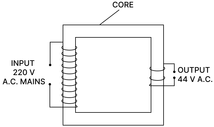
(c) As 220 V is converted to 44 V hence, it is a step down transformer.
The diagram below shows a magnetic needle kept just below the conductor AB which is kept in North South direction.
(a) In which direction will the needle deflect when the key is closed?
(b) Why is the deflection produced?
(c) What will be the change in the deflection if the magnetic needle is taken just above the conductor AB?
(d) Name one device which works on this principle.
Answer
(a) North pole of needle deflects towards east.
(b) On passing current through the wire AB, a magnetic field is produced around the wire which aligns the magnetic needle in it's direction.
(c) The direction of deflection gets reversed i.e., now it deflects towards west.
(d) An electric bell works on this principle.
How do the input and output powers in a transformer compare. State the assumption made.
Answer
For an ideal transformer, when there is no energy loss, the output power will be equal to the input power. i.e., power in secondary coil = power in primary coil or EsIs = EpIp
Assumption made is that the resistance is negligible and there is no energy loss.
The magnetic flux through a coil having 100 turns decreases from 5 milli weber to zero in 5 second. Calculate the e.m.f. induced in the coil.
Answer
Given,
- Number of turns (N) = 100 turns
- Decrease in the flux = 5 milli weber (0.005 weber to 0 weber),
- Time = 5 second
From relation,
e.m.f. induced e = N × rate of increase of magnetic flux
Substituting the values in the formula we get,
Hence, the e.m.f. induced in the coil is 0.1 V or 100 m V.
The primary coil of a transformer has 800 turns and the secondary coil has 8 turns. It is connected to a 220 V a.c. supply. What will be the output voltage?
Answer
Given,
- Np = 800
- Ns = 8
- Ep = 220 V
- Es = ?
Now,
Substituting the values in the formula we get,
Hence, output voltage = 2.2 V
A transformer is designed to give a supply of 8 V to ring a house-bell from the 240 V a.c mains. The primary coil has 4800 turns. How many turns will be in the secondary coil?
Answer
Given,
- Es = 8 V
- Ep = 240 V
- Np = 4800
- Ns = ?
We know that,
Now,
Substituting the values in the formula we get,
Hence, the number of turns in the secondary coil is 160.
The input and output voltages of a transformer are 220 V and 44 V respectively. Find : (a) the turns ratio (b) the current in input circuit if the output current is 2 A.
Answer
(a) Given,
- Ep = 220 V
- ES = 44 V
Now,
Substituting the values in the formula we get,
Hence, turns ratio = 1 : 5
(b)
- Is = 2 A
- Ip = ?
From relation,
Substituting the values in the formula we get,
Hence, input current = 0.4 A
A student in a laboratory wants to light a bulb of 6 W, 11 V rating with a supply of 220 V. Mention the kind of transformer he should use. Also calculate the turn ratio for the transformer recommended by you.
Answer
Since the supply voltage (220 V) is much higher than the required voltage (11 V), the student needs a step down transformer to reduce the voltage.
Given,
- Ep = 220 V
- Es = 11 V
Let number of turns at primary coil be Np and at secondary be Ns respectively.
Now,
Turn Ratio =
Hence, recommended turn ratio should be .