
Physics
The diagram below shows a bulb connected by dual control switches. Observe the diagrams and answer the questions that follow.
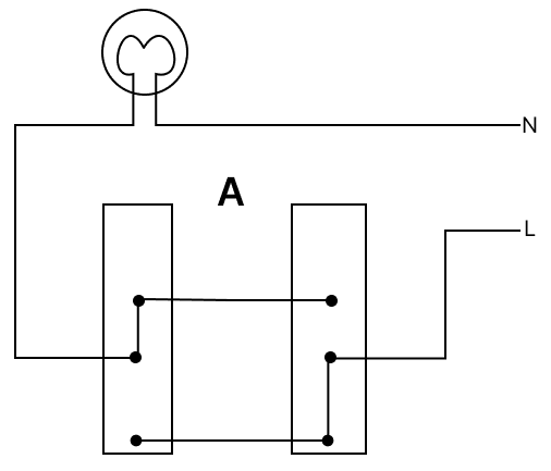
(a) Which of the above circuits will be able to switch ON or switch OFF the bulb using both switches?
(b) At present, in which circuit is the bulb glowing?
(c) If we interchange the L and N wires in circuit B, will the circuit work?
Household Circuits
12 Likes
Answer
(a) Both circuits will be able to switch ON and switch OFF the bulb using both switches.
(b) Circuit B
(c) Yes, the circuit will function.
Explanation:
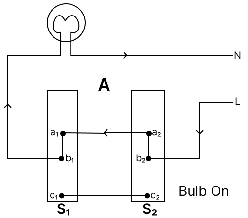
(a) Circuit A : Figure illustrate the dual control switch in an electric circuit. Two such switches S1 and S2 are used. The figure A shows the 'off' position of the bulb.
Figure A
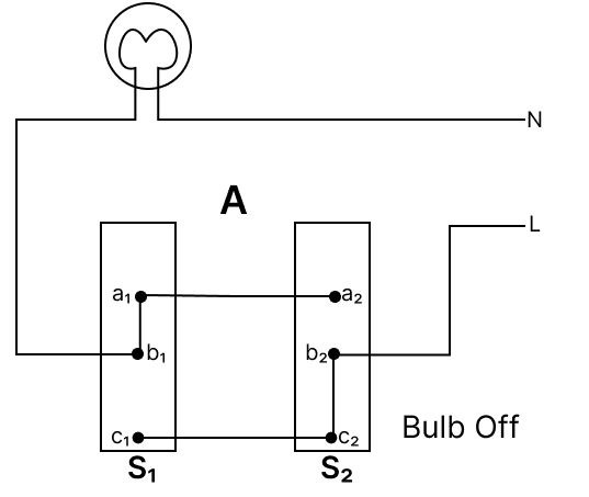
The bulb can now be switched 'on' independently by either the switch S1 or the switch S2.
If the switch S1 is operated, the connection 'b1a1' is changed to 'b1c1', which completes the circuit and the bulb lights up and by reversing the process it can turn off.
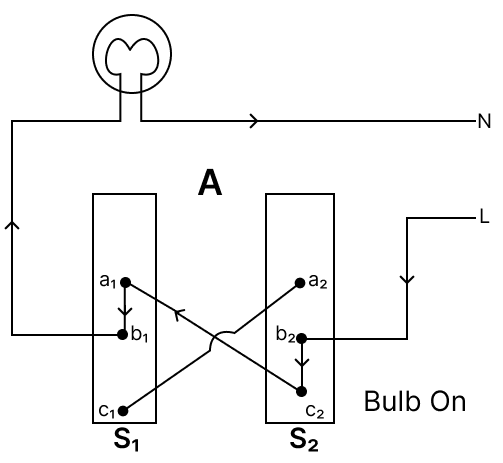
Figure A1
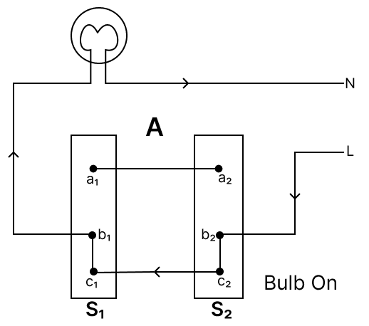
Similarly, If the switch S2 is operated from the position shown in figure A the connection 'b2c2' changes to 'b2a2', which again completes the circuit and the bulb lights up and by reversing the process it can turn off.
Figure A2
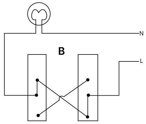
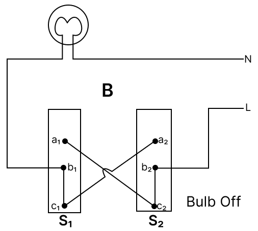
Circuit B : This figure also illustrate the dual control switch in an electric circuit. Two such switches S1 and S2 are used, and the Figure B shows the 'on' position of the bulb.
Figure B
The bulb can now be turned 'off' independently by either the switch S1 or the switch S2.
If the switch S1 is operated, the connection changes from 'b1a1' to 'b1c1', which breaks the circuit and turns the bulb off. Reversing the process restores the connection, turning the bulb on.
Figure B1
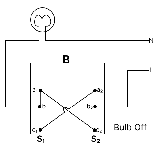
Similarly, when the switch S2 is operated from the position shown in Figure B, the connection changes from 'b2c2' to 'b2a2', breaking the circuit and turning the bulb off. Reversing the process reconnects the circuit, allowing the bulb to turn on.
Figure B2
(b) In circuit A current flows from:
live wire ⟶ b2 ⟶ c2 ⟶ c1
Hence, it does not complete the circuit.
In circuit B current flows from:
live wire ⟶ b2 ⟶ c2 ⟶ a1 ⟶ b1 ⟶ bulb ⟶ Neutral wire
Hence, it completes the circuit.
(c) A standard incandescent light bulb is NOT dependent on the polarity of the connection for its basic operation (lighting up). So by changing L and N wires, the circuit will function.
Answered By
3 Likes
Related Questions
Bandish and Parag, on a trek to Sandakpu, halted at a tea house in Tumbling. The picture above shows the entrance door of the tea house. They saw the tumbrel filled with water hanging from top rigid support passing through the door. On enquiring about the tumbrel, the owner of the tea house, he said that it acts as a pullback (door closure) after opening and releasing the door.
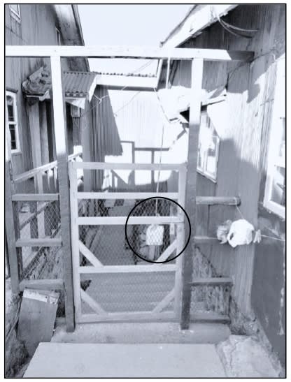
(a) Explain how the tumbrel helps to close the door on its own.
(b) Name the principle involved.
A convex lens of power +5 D has an object placed at a distance of 50 cm in front of the lens.
(a) State the nature of the image formed.
(b) What is the definite distance, towards or away from the lens, the object should move so that the image is not seen?
Observe the electric circuit below and answer the questions that follow.
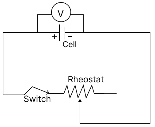
(a) If we increase the current in the above circuit using a rheostat, will the reading of the voltmeter decrease or increase?
(b) Give a reason for your answer in ‘a’.
(c) The present reading of the voltmeter is 2 V, and the current in the circuit is 0.8 A. Calculate the potential drop when the current in the circuit becomes 1 A. Given E = 3 V.
Pavel took an earthen pot which was filled with water up to its brim. The earthen pot was conical in shape and kept with its apex in downward direction.
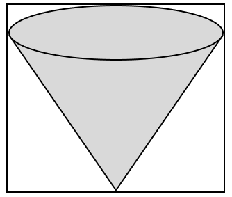
(a) If the vertical height of the earthen pot is 12 cm, where does its centre of gravity lie?
(b) Pavel poured out all the water from the pot. How will its centre of gravity shift towards the open end or towards its apex?
(c) Pavel wanted to grow a plant in the given pot. So, he filled it completely again with some soil. What will be the new position of its centre of gravity?